1
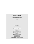
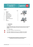
TABLE of CONTENTS FLOALARM OVERVIEW .............................................................................................................. 2 rel. 1.2 SET-UP ...................................................................................................................... 3 CONNECTING POWER SUPPLY .................................................................................. 3 CONNECTING INPUTS ............................................................................................... 3 CONNECTING RELAY OUTPUT ................................................................................. 3 FIRST POWER-UP .................................... FEHLER! TEXTMARKE NICHT DEFINIERT. Alarm System K4 / K8 PROGRAMMING .................................................................................................... 4 OPERATION ............................................................................................................ 6 ALARM MANAGEMENT............................................................................................. 6 TEST AND PROGRAMMING CHECK ............................................................................ 7 NO / INVALID SETUP PARAMETERS ........................................................................... 7 SUMMARY OF OPERATIONS ...................................................................................... 8 MECHANICAL INFORMATION .......................................................................... 9 ELECTRICAL CONNECTIONS.......................................................................... 10 TECHNICAL CHARACTERISTICS ................................................................... 11 DECLARATION OF CONFORMITY .............................................................................. 12 OVERVIEW User manual September 2013 Spectron Gas Control Systems GmbH Fritz-Klatte-Str. 8 - 65933 Frankfurt / Main – Germany Tel. +49 (0)69 - 38016 - 0 Fax +49 (0)69 - 38016 - 200 FLOALARM is especially conceived to monitor alarm conditions in compressed gas storages and supply pipelines. Two types are available: K4 with four alarm inputs and K8 with eight alarm inputs. All alarm inputs are compatible with popular switch sensors and inductive proximity sensors type Namur. The alarm status is testified by visual and acoustic signals. Visual signals include 4 (8) red leds, associated to each alarm input. Blinking status of red led testifies that the corresponding alarm input is active and this alarm condition is still unacknowledged. Fixed lighted status of red led testifies that the corresponding alarm input is active and this alarm condition was already acknowledged. Acoustic signal indicates one or more unacknowledged alarm conditions. All current unacknowledged alarm conditions become acknowledged and the acoustic signal switches off by pushing CANCEL HOOTER pushbutton. The TEST pushbutton starts the standard test of all signaling devices and the programming check cycle. A relay output is available to drive an additional hooter or an external alarm indicator. All programming functions can be set and modified by two pushbuttons on the front panel. 2 SET-UP PROGRAMMING WARNING ! – For safety reasons, the installing operations must be performed in accordance with the instructions of this manual, by qualified operators only; disconnect power supply line from the equipment before opening the housing. The manufacturer rejects whichever responsibility for accidents or damages due to negligence of these recommendations. For use with flammable gases or input signals from ex-protected areas the European Directive 94/9/EC (ATEX) must be observed. Signal sources in ex-protected areas must only be operated on intrinsically safe signal circuits using suitable safety barriers. Notice: The FLOALARM-unit must be installed outside the ex-protected area! Programming parameters can be set or modified by the pushbuttons on the front panel. You can set operation and delay of each alarm input, besides buzzer and relay output operation. Tables below show the alarm condition related to the input operation and delay for both sensor types and supply some suggestions about remaining setting. Alarm inputs PROGRAMMING PARAMETER ALARM CONDITION FOR SWITCH SENSOR INDUCTIVE NAMUR Normally Closed (NC) Connecting Power Supply Normally Open (NO) Use 1.5 mm2 section cables. Put a 2 A bipolar security interrupter on the power supply line. No delay Delay 2 sec Immediate Delayed 2 seconds Buzzer Connecting Inputs 2 Connect each sensor using bipolar 0.25 – 0.5 mm section cable. Shielded cables with shields connected to earth are suggested, but not mandatory. Connecting Relay Output Use 0.5 to 1.5 mm2 section cables, in function of switching current and line length. Don’t forget that maximum working voltage is 220 Vac and maximum current 1 A for this output. OPERATION SUGGESTIONS Use this setting if the alarm equipment is placed outdoor or in Continue industrial environments and, in general, when the maximum volume is required. Use this setting if the alarm equipment is placed in site Pulse habitually frequented by people and, in general, when a moderate volume is required. Use this setting to disable the alarm sound. OFF Relay output OPERATION Buzzer repeater Cumulative alarm 3 4 SUGGESTIONS Use this setting to drive an additional external hooter in case one or more unacknowledged alarm conditions are in progress. Use this setting to drive an additional external alarm indicator. Logic N.C. Push and hold TEST pushbutton: system starts test and programming check cycle then, after about 10 seconds, switches OFF all leds. Release TEST button after leds switch off: the system enters the programming mode and begins step 1 of the programming sequence. During programming sequence, push CANCEL HOOTER to select the desired option, push TEST to confirm current setting and jump to next step; Programming sequence Prg User First Option Step Second Option Third Option Function Interface (default) Input 1 Normally Open Normally Closed 1 ‐‐‐‐‐ Operation LED 1 fixed light fast blinking Input 1 LED 1 = ON No delay Delay 2 sec 2 ‐‐‐‐‐ Delay Buzzer Short buzz Long buzz Input 2 Normally Open Normally Closed 3 ‐‐‐‐‐ Operation LED 2 fixed light fast blinking Input 2 LED 2 = ON No delay Delay 2 sec ‐‐‐‐‐ 4 Delay Buzzer Short buzz Long buzz Input 3 Normally Open Normally Closed 5 ‐‐‐‐‐ Operation LED 3 fixed light fast blinking Input 3 LED 3 = ON No delay Delay 2 sec 6 ‐‐‐‐‐ delay Buzzer Short buzz Long buzz Input 4 Normally Open Normally Closed 7 ‐‐‐‐‐ operation LED 4 fixed light fast blinking Input 4 LED 4 = ON No delay Delay 2 sec 8 ‐‐‐‐‐ Delay Buzzer Short buzz Long buzz ‐‐‐‐‐ ‐‐‐‐‐ ‐‐‐‐‐ ‐‐‐‐‐ ‐‐‐‐‐ ‐‐‐‐‐ Buzzer All LEDs OFF Continue mode Pulse mode Disabled 9 (17) Operation Buzzer Continue tone Pulse tone Off Relay OUT All LEDs = ON Buzzer repeater Cumulative Alarm 10 (18) ‐‐‐‐‐ Operation Buzzer Pulse tone OFF EXIT from PROGRAMMING MODE ‐ RETURN to RUNNING MODE The exit from Programming Mode occurs at the end of the programming sequence or by the 30-seconds key-timeout. The exit by timeout also preserves all previous changes, except for those corresponding to the current input. For example: if timeout occurs while the system stands in step 8, only previous modifications concerning the inputs 1, 2 and 3 will be preserved. On the contrary, the exit by timeout does not recover a NO / INVALID SETUP PARAMETERS condition (refer to corresponding section). 5 OPERATION Alarm management The standard alarm sequence includes three steps: Case 1: acknowledgement before the end of the alarm event 1. Start of alarm event: input switches from normal to alarm condition. Buzzer switches on and the corresponding alarm led becomes blinking, indicating an unacknowledged alarm status. 2. Alarm acknowledgement: user pushes CANCEL HOOTER pushbutton. Buzzer stops and alarm led switches from blinking to fixed, indicating an acknowledged alarm status. 3. End of alarm event: input switches from alarm to normal condition. Alarm led switches from fixed to off. Case 2: acknowledgement after the end of the alarm event 1. Start of alarm event: input switches from normal to alarm condition. Buzzer switches on and the corresponding alarm led becomes blinking, indicating an unacknowledged alarm status. 2. End of alarm event: input switches from alarm to normal condition. Same signals continue, system remains in previous alarm status. 3. Alarm acknowledgement: user pushes CANCEL HOOTER pushbutton. Buzzer stops and alarm led turns off. The alarm management is “with memory”; namely, if the end of the alarm event occurs before the acknowledgement, the equipment remains in unacknowledged alarm status, until the acknowledgement. Acknowledgement operation is effective over all the current alarms. 6 Test and Programming check Pushing Test button, system turns on all alarm leds, relay and buzzer for three seconds (standard test), then shows current programming parameters through the signaling sequence described in table below. The duration of each step is about three seconds Programming check sequence Step 1 2 3 4 ‐‐‐‐‐ 5 (9) 6 (10) Checking Input 1 Input 2 Input 3 Input 4 ‐‐‐‐‐ Buzzer Relay OUTPUT Function Signaling Operation Led 1 Delay Buzzer Operation Led 2 Delay Buzzer Operation Led 3 Delay Buzzer Operation Led 4 Delay Buzzer ‐‐‐‐‐ Operation Buzzer All LEDs OFF Operation Buzzer All LEDs ON First Option Second Option NC fast blinking Delayed Long buzz NC fast blinking Delayed Long buzz NC fast blinking Delayed Long buzz NC fast blinking Delayed Long buzz ‐‐‐‐‐ Continue Continue tone NO fixed light No delay Short buzz NO fixed light No delay Short buzz NO fixed light No delay Short buzz NO fixed light No delay Short buzz ‐‐‐‐‐ Pulse Pulse tone Buzzer repeater Pulse tone Cumulative al. Always OFF Summary of operations Visual and acoustic signals in working mode DEVICE Third Option ‐‐‐‐‐ Alarm led 1(…. 8) ‐‐‐‐‐ Buzzer STATUS CONDITION OFF Blinking fixed lighted flashing (all alarm leds) OFF ON Normal condition 1(…. 8) Unacknowledged alarm 1(…. 8) Acknowledged alarm 1(…. 8) No or invalid setup parameters No or acknowledged alarms / Disabled One or more unacknowledged alarms ‐‐‐‐‐ ‐‐‐‐‐ Buzzer operation ‐‐‐‐‐ ‐‐‐‐‐ BUZZER SETTING OPERATION IN ON STATUS ‐‐‐‐‐ Continue tone Pulse tone Disabled ‐‐‐‐‐ always ON 0.5 sec ON / 1.5 sec OFF Always OFF ‐‐‐‐‐ Disabled OFF Output Relay operation ‐‐‐‐‐ RELAY SETTING Buzzer repeater Cumulative alarm relay No / invalid setup parameters After a programming error or before first programming, the programming parameters in memory are invalid or missing. In this condition, the system does not operate and flashes all alarm leds periodically. Perform a full programming sequence to restart the system (refer to FIRST POWER-UP section for details). 7 8 OPERATION Follows the status of the buzzer as shown in table above, without consideration for the buzzer setting OFF if one or more alarms are in progress ON if no alarm are in progress Mechanical information Electrical connections Warning Each sensor must be directly connected to the corresponding screw connector only and using both wires. Avoid connections different from that shown in diagram above. CN1 – CN8 Alarm inputs Pin – + Mechanical switch sensor Solid state switch sensor – + COM NO or NC CN9 Relay Output Pin 1 2 3 9 10 Signal NC COM NO Inductive sensor NAMUR type normal / ATEX – white cable / - blue cable + brown cable/ + brown cable CN10 Supply 220 Vac Pin L N Signal 220 Vac – (L) 220 Vac – (N) DECLARATION OF CONFORMITY TECHNICAL CHARACTERISTICS INPUTS specifications V(max) = 15 Vdc; I(max) = 20 mA INPUTS compatibility Standard mechanical switch sensors Solid state PNP / NPN switch sensors, DC only Inductive proximity sensors type NAMUR RELAY OUTPUT V(max) = 220 Vac; Imax = 1 A NO and NC contacts available SUPPLY VOLTAGE 220 Vac / 50-60 HZ, P(max) = 8 VA Fuse 220 V / 0.1 A HOUSING IP65 plastic box for wall mounting K4 type: 200 x 120 x (h) 57 mm K8 type: 200 x 120 x (h) 77 mm Namur specifications SUPPLY VOLTAGE 5 Vdc < +VS < 25 Vdc Target Present IL< 1mA Target Absent 3mA < IL < 15 mA LOAD CURRENT Made by: AMBRA Sistemi s.r.l. Grugliasco (TO) Italy 11 12