1
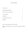
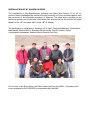
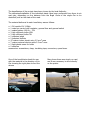
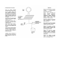
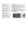
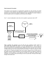
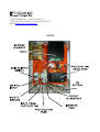
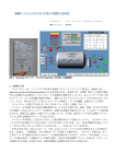
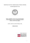
Department of Agricultural, Forestry and Environment Economic and
Engineering
University of Torino - Italy
First installation of renewable Energy based plants at the homes of Mongolian
shepherds
Place: Mongolia
FINAL REPORT
Stefano Bechis
TABLE OF CONTENTS
ACTIVITY IN ITALY
3
OPERATIONS BEFORE DELIVERIES
4
INSTALLATION OF DC PLANTS ON GERS
6
PLAN OF DELIVERIES
12
DELIVERIES LIST
13
INSTALLATION OF THE AC PLANTS
15
REFERENCES
18
ANNEX 1 – USER’S MANUAL FOR THE DC PLANT FOR GERS
ANNEX 2 – USER’S MANUAL FOR THE AC PLANT FOR THE SCHOOL AND THE MEDICAL
CENTRE
ACTIVITY IN ITALY
The first steps of this project have been to get in touch with the CNR-IRPI Institute
(National Research Council, Institute for Hydro geological Protection) in Padua, that was
already working in an area in southern Mongolia, and with the Mongolian consulate in
Trieste.
The Director of CNR-IRPI is Prof. Bruno Marcolongo who is in charge by the Italian
Ministry of Foreign Affairs to coordinate and follow all Italian cooperation projects in
Mongolia.
A meeting was held in Padua on February 12th 2003, in which it was decided to ask the
partnership to the Mongolian Academy of Science (MAS), and to work in the
Bayankhongor province close to the Orog Nuur (lake Orog), where the IRPI had a joint
cooperation project with the MAS. The Mongolian Academy of Science accepted the
partnership.
On May 13th 2003 a second meeting was held in Padua with the representatives of the
Mongolian Academy of Sciences and it was then decided to work in the territory of the
Bogd Soum (village) a small centre South of the town of Bayankhongor. The area is
located in the centre of a large plain in the middle of the Khangay and Gobi Altayn
mountain chains.
The MAS representatives assumed the task to contact the local authorities to obtain
indications of possible local technicians and a list of beneficiaries.
After this meeting it was decided to proceed to install n. 20 DC SHS (Solar Home Systems)
with a module rated 110 Wp each on Gers (“ger” is the name of the traditional Mongolian
tent), and n. 2 AC systems, one for a school and one for a hospital, each equipped with a
540 Wp PV array.
The materials have been purchased from Italian enterprises and sent to Mongolia in a
container. Total mass was about 1800 kilograms. Transport took about 50 days, from
August 12th to October 3rd.
On October 13th 2003 a mission left Italy for Mongolia for the installation of the systems.
OPERATIONS BEFORE DELIVERIES
The first week in Mongolia was used for recovering the material from the customs, preassembly some parts of the plants and to prepare the delivery certificates and manuals.
During pre-assembly the main boxes of the 20 SHS DC systems were prepared, with
charge regulators, relays, switches, fuse, cables and plugs.
Pre-assembling of elements at the
Mongolian Academy of Sciences in
Ulaan Baatar
In a second time twenty light transparent plastic cases were prepared with 15W
fluorescent bulbs and another twenty equipped with 7W fluorescent bulbs.
The main boxes have been prepared with three cables coming out from them: one for the
connection with the PV module, ending in a 10A plug, a second for the connection with
the battery, ending in a 16A plug and a third going directly to the user points.
As the nomads move four times a year as an average they have to disconnect the system
from its parts to allow transport. The choice of different plugin-sockets for coupling the
system to the battery and the PV module is to avoid mistakes when re-connecting the
parts after moving. Sockets and plugs with the central ground contact have been used.
The ground has been used for the positive, not to reverse polarity. Sockets have been
connected to PV module and to the battery, not to have exposed part with a voltage.
Pre-assembly of parts was finished in Bayankhongor province, where the cables and the
7W bulbs were prepared.
Pre-assembly of parts allowed simpler operations at nomad’s houses, leaving more time
for explainations on the system to the beneficiaries.
As a whole the scheme of the plant is as follows:
A local technician has been trained on the use and maintenance of the SHS, and has taken
the task to look after the installations.
A small manual on the use and maintenance of the system has been written in two
languages, Mongolian and English and a copy has been given to each beneficiary. This
manual (see attached) is composed by four pages in which are explained the project, how
the plant is made, how it normally works, and a to-do list for the disconnecting –
connecting when moving the Ger.
The elements of the two larger AC plants have been left in Ulaan Baatar to be installed in
a second time in a school and in a medical centre in a village in the Arkhangay province
(central Mongolia).
INSTALLATION OF DC PLANTS ON GERS
The installations in the Bayankhongor province took place from October 20 to 24. To
perform those installations the personnel of the University of Torino worked together with
the personnel of the Mongolian Academy of Sciences. Two days were necessary to get
there and another two to get back, then taking into account the trip the mission left Ulaan
Baatar on the 18th and came back on the 26th of October.
The participants to installations: Standing, left to right: Tsegmid Battsetseg, Yondonjamts
Narandavaa, Stefano Bechis, Byambaa Gunchinsuren, Goonii Lhundev; sitting:
Yondonjamts Nyamdavaa, Andrea Vilianis, Damchii Gan-Ochir
For the days in the Bogd Soum, the Mission base has been the Italian - Mongolian joint
centre prepared by the CNR-IRPI in cooperation with the MAS.
the Italian - Mongolian
joint centre prepared by
the CNR-IRPI in
cooperation with the MAS
The outward journey took about eight hours from Ulaan Baatar to Arvayheer (about 430
km on asphalt road in poor conditions), an overnight in Arvayheer and another seven
hours to arrive to Bogd (about 240 km almost all on natural road).
A ceremony was organised by Bogd inhabitants on mission’s arrival.
First day: 430 km in 8 hours
A stop for a flat tyre
Second day: 240 km in 7 hours
In Mongolia there is a large number
of free horses
The welcome ceremony
ant the entrance of the
Bogd soum
The Bogd Soum has 3500 inhabitants, average life expectancy is 65 years, about 80
children are born each year. While about 20 – 30 persons die each year.
Bogd school counts 620 pupils, of which 80 are residents in the boarding school. The
hospital has 18 beds and two doctors.
To provide energy to the hospital, a hybrid system composed by a photovoltaic array and
a wind charger was installed in 1998. The PV array is composed by 16 modules rated 55
Wp each. The eolic rotor diameter is 5 m. Those materials have been installed in the
framework of a Tacis program, but local people say that the wind charger lasted only a
short period and then broke down. At the mission’s time (2003) it was no longer in the
village. The PV array is placed on a manual one-axis tracker that is not moved and is fixed
facing Southwards. The battery was in a bad state, with salts coming out from the poles.
The post office has an autonomous PV system composed by 18 modules 50 Wp each.
General view of the Bogd soum
The beneficiaries of the project have been chosen by the local Authority.
The deliveries/installation of the individual plants have been performed from three to six
each day, depending on the distance from the Bogd Soum of the single Ger to be
electrified, and on the state of the road.
The material delivered to each beneficiary was as follows:
n. 1 PV module 12V 110Wp
n. 1 main box control with regulator, general fuse and general switch
n. 1 sealed battery 100 Ah – 12V
n. 3 high efficiency bulbs 15W
n. 3 high efficiency bulbs 7W
n. 2 polarized plugs
n. 2 polarized sockets
n. 15 metres indoor electric wire 2.5 mm2 area
n. 7 metres external electric cable 2.5 mm2 area
n. 2 light plastic cases for bulbs
n. 2 switches
accessories: screwdrivers, clasp, insulating tape, connectors, spare fuses.
One of the beneficiaries leads the van
with the material in the direction of his
Ger showing the right place to ford the
stream
Many times there was simply no road,
and it was necessary to drive directly
on the prairie
During the installation the SHS composition and operation have been explained in detail,
together with the maintenance and the operations to be done to disassemble and
reassemble it when displacing the Ger.
At the end of every installation a certificate of delivery has been signed, in four copies:
one for the beneficiary, one for the local Authority, one for the Mongolian Academy of
Science and one for the University of Torino.
PLAN OF DELIVERIES
Disposition of the places where the installation have been performed. Installation n. 1, 18,
19, 20 took place in the centre of Bogd Soum, named Horiult.
DELIVERIES LIST – Names of beneficiaries expressely omitted for privacy reasons
N
PLACE AND GPS
COORDINATES
Number and age of
family components
occupation
1
Horiult
N45011’ 50,8’’
E100046’37,7’’
Elev: 1268 m
Aman usnii muhar
N45011’ 06,2’’
E100050’49,2’’
Elev: 1239 m
Zuun gol
N45006’ 03,5’’
E100050’10,7’’
Elev: 1234 m
5 persons
Head of family 41,
wife 40,
3 sons: 15, 13, 10
3 persons
family head 65,
wife 72,
grandson 16
8 persons
family head 46,
wife 40,
6 sons: 24, 20, 18,
15, 13, 3
6 persons
family head 36,
wife 35,
mother 69,
3 sons 8, 7, 4
5 persons
family head 71,
wife 65,
3 sons 43, 22, 21
5 persons
family head 46
wife 45
3 sons 16, 14, 12
6 persons
family head 47,
wife 44,
4 sons 22, 18, 15, 13,
5 persons
family head 62,
4 sons 37, 29, 23, 14
Driver,
electronic
technician
2
3
4
Tsutgalangiin eh
N45006’ 42,9’’
E100045’24,7’’
Elev: 1228 m
5
Undor dob
N45006’ 18,6’’
E100045’25,0’’
Elev: 1230 m
Shavgiin haya
N45006’ 24,2’’
7E100041’21,6’’
Elev: 1219 m
Aman Us
N45010’ 25,4’’
E100051’47,8’’
Elev: 1255 m
Aman Us
N45010’ 12,8’’
E100051’51,4’’
Elev: 1233 m
Haya hudag
N45013’ 48,1’’
E100053’02,7’’
Elev: 1235 m
Dalan turuu
N45003’ 41,4’’
E100031’43,1’’
Elev: 1236 m
6
7
8
9
10
6 persons
family head 42,
wife 37,
4 sons 16, 13, 10, 8
6 persons
family head 34,
wife 27,
mother 69,
sister 17,
brother 18,
sons 15
Times a year the
Ger is relocated and
distance
-
Retired,
former
Herdsman
4 a year 10 km as
an average
Herdsman,
former tractor
driver
4 a year 15-20 km
as an average
Herdsman ex
tractor driver
3 a year per 10 km
as an average
Herdsman
2 a year per 10 km
as an average
Herdsman
3 a year per 15 km
as an average
Herdsman
3 a year per 30-40
km as an average
Herdsman
3-4 volte a year per
30 km as an
average
Herdsman
5-6 a year per 20
km as an average
Herdsman
4-5 a year 30 km as
an average
N
11
12
13
14
15
16
17
18
19
20
PLACE AND GPS
COORDINATES
Shar dov
N45008’ 38,1’’
E100030’07,1’’
Elev: 1231 m
Zuun goliinadag
N45006’ 39,7’’
E100052’14,6’’
Elev: 1218 m
Zuun gol
N45006’ 13,9’’
E100051’13,4’’
Elev: 1221 m
Dund gol
N45006’ 18,2’’
E100049’49,6’’
Elev: 1228 m
Aman goliin Ungon
shirge
N45017’ 06,6’’
E100043’24,7’’
Elev: 1213 m
Zuun tatuur
N45019’ 21,2’’
E100041’42,2’’
Elev: 1335 m
Hanhiltiin am
N45014’ 42,1’’
E100045’47,9’’
Elev: 1289 m
Horiult
N45011’ 52,5’’
E100046’30,7’’
Elev: 1299 m
Horiult
N45011’ 52,5’’
E100046’25,0’’
Elev: 1275 m
Horiult
N45011’ 57,3’’
E100046’14,5’’
Elev: 1282 m
Number and age of
family components
occupation
4 persons
family head 65,
3 sons, 33, 26, 18
Herdsman
Displacement
number and
distance
4 a year 30 km
4 persons
family head 26,
wife 26,
2 sons, one 3 y.o., the
other only 1 month
5 persons
family head 40,
wife 35,
3 sons 15, 12, 7
3 persons
family head 65,
wife 57,
sons 26
5 persons
family head 38,
wife 37,
3 sons 14, 11, 8
Herdsman
2 times a year 5 km
Herdsman
4 a year 30 km
Herdsman
7 a year 40 km
Herdsman
5 a year 70 km
5 persons
family head 64,
wife 54,
3 sons 24, 22, 15
5 persons
family head 30,
wife 29,
3 sons 11, 6, 3
4 persons
family head 51,
wife 45,
2 sons 20, 12
4 persons
family head 54,
wife 48,
2 sons 22, 17
5 persons
family head 50,
wife 48,
3 sons 22, 18, 14
Herdsman
3 times 5 km
Herdsman
5-6 times a year 20
km
Head of the
local authority
-
Head of the
local hospital
-
Herdsman
At least 2 a year
about 20 km
During the stay in Bogd two meetings with the local Authority and the village doctor have
been organised, to discuss monitoring of plants and reports to the MAS and then to
DEIAFA.
INSTALLATION OF THE AC PLANTS
During the last five days in Ulaan Baatar the two AC plants were prepared for set up and
informations for installation were provided to the MAS personnel to perform this
installation in a second time, possibly during a later visit.
During one and a half day has been showed to the MAS personnel how to connect the
various components, in a practical way. Special care has been put in explaining how to
avoid possible incidents (short circuits and so on).
The installation responsibility was assigned to a Mongolian private company specialized in
renewable energies called Monmar. In the last two days the English manual for 220 V AC
plants was written and printed (see ANNEX 2).
The installations took place during Springtime 2004, in the school and hospital of Murun
Bag, part of the Tariat soum, in Arkanghay province.
Localisation on the Map of the Tariat Soum, close to which is the Murun Bag where the AC
plants were installed.
The delivered material for each plant was as follows:
n. 6 PV modules 12V 90Wp
n. 1 regulator
n. 1 24V DC – 220V AC, 1500 VA inverter
n. 4 tubular batters 157 Ah – 12V
n. 35 high efficiency bulbs
n. 10 plugs
n. 10 sockets
100 m electrical cable area 1.5 mm2 for indoor use
150 m electrical cable area 2.5 mm2 for outdoor use
30 m electrical cable area 4.0 mm2 for outdoor use
n. 30 bulb plastic case
n. 30 junction boxes
accessories
During the month of July 2004 a monitoring mission went to the Tariat soum to control
the work done in the previous months, and the plants were found correctly installed and
working. The personnel of the hospital and the school were completely satisfied.
The PV array at the hospital of the Murun Bag
One of the rooms inside the hospital, with bulbs and switches provided by the project
Group photo outside the school at the Murun Bag
The regulator, inverter and batteries inside the school, giving electricity to a VHS and TV
for teaching activity
REFERENCES
Stefano Bechis
Dipartimento di Economia e Ingegneria Agraria, Forestale e Ambientale
Sezione di Meccanica
Università di Torino
via Leonardo da Vinci 44, 10095 Grugliasco (TO) Italia
tel. +39 011 6708589
fax +39 011 6708591
email: [email protected]
This project has been realized with the financial aid of Regione Piemonte, Torino, Italy
ANNEX 1
USER’S MANUAL FOR THE DC PLANT
ANNEX 2
MANUAL FOR THE USE OF THE PLANTS IN AC
FOR THE SCHOOL AND THE MEDICAL CENTRE
USER’S MANUAL
What is this system
The PROMEC system provides 220V AC electric energy, using sun as source by means of
photovoltaic modules. Together with the plant to produce energy the 220V AC line and some
user points are supplied.
The system to produce AC electricity is composed by:
n. 6 PV modules 12V 90Wp
n. 1 energy controller
n. 1 24V DC – 220V AC, 1500 VA inverter
n. 4 tubular batteries 157 Ah – 12V
The energy controller contains: a battery charger (16 A - 28 V), PV modules control,
switches and fuses.
Together with the system come some spare parts as fuses and so on.
Fig. 1 – General layout of the system
How to make connections
WARNING:
WHEN MAKING CONNECTIONS TAKE SPECIAL CARE OF POLARITY. AN
INVERSION OF POLARITY WILL CAUSE VERY SERIOUS DAMAGE TO THE INVERTER
The batteries are to be connected first in series in groups of two and then in parallel to
the system, in order to obtain 24V DC (see Fig.2).
The PV modules are to be connected in series in groups of two and then in parallel to the
system in order to obtain 24 V DC.
The inverter is to be connected to the energy controller by means of the specific
connections. DO CONNECT TO THE INVERTER FIRST THE NEGATIVE (BLACK) POLE AND
THEN THE POSITIVE ONE (RED). While doing connections the general inverter switch
must be turned OFF.
The user points are to be connected to the inverter by means of the Shuko plug.
Fig. 2 - The four supplied batteries correctly connected
How to operate the system
This system can be used alone or coupled with a generator set. The generator set should
be turned on when batteries are discharged, because of a sequence of cloudy days or
because of very intensive use. When the generator set is operating, the battery charger of
the unit sends current to the batteries, until they are fully charged.
Fig. 3 – correct configuration when the unit is coupled to a generator that is OFF
ENERGY
CONTROLLER
GENERATOR
SET
(OFF)
No current from the gen set
to the energy controller
Energy
comes in
from PV
modules
and/or
batteries
INVERTER
The user points are plugged
to inverter and energy comes
from the PV system
When operating the generator set, the plug into the inverter’s socket should be
UNPLUGGED AND CONNECTED DIRECTLY TO THE GENERATOR SET. This to better use
the current provided by the generator set. Please note that if this is not done, and the
energy is given to user points while charging batteries with the generator set, the charge
of batteries will take more time and fuel, and be not efficient. In case for example the user
points ask for 16 Amps the batteries will never charge, because all the current given by
the battery charger will be delivered to the user points, without any chance to charge the
batteries. On the contrary, if the plugs are correctly set during the charge by the
generator set, the latter will provide energy to the user points and 16 Amps to the battery
charger at the same time.
Fig. 4 – Correct configuration when the unit is coupled to a generator that is ON. The
generator set supplies energy both to batteries through the battery charger in the energy
controller and to the user points. The inverter is disconnected from the user points.
ENERGY
CONTROLLER
GENERATOR
SET
(ON)
Current flows from the gen
set to the energy controller
The user points are plugged
directly to the generator set
Energy
goes to
the
batteries
INVERTER
Current goes to the user points
coming from the generator set
About the inverter
The DAFNE 1524 inverter converts 24V DC electric current into 220V AC at 50 Hz. The
maximum power is 1500 VA. Peak power of 3500 VA can be supplied for a short period
(5 seconds) in order to start electric engines. This supply of DC current must range
between 19 and 32V. The unit must be located in a dry and aerated environment. Its
position must be vertical. It can be hung on a wall or left on the ground.
All electrical connections and operations are performed on the upper console
where there are (see photo):
1. DC connections in the upper part ( + RED and – BLACK 24 V DC INPUT)
2. Alternate current socket (Shuko type, in the centre of the console)
3. General ON OFF switch with light, on the right of the general switch
4. The thermal protection against overloads (black button near the general switch, with
RESET OVERLOAD writing)
5. The ground connection (on the left of the alternate current socket with SAFETY
GROUND writing)
Fig. 5 – The inverter’s console with the connections and switches
To operate the unit, make the connections to the Energy Controller as described before,
then plug in the user points by means of the Shuko plug into the console socket, and
finally switch on the main inverter switch. If a load is detected by the inverter, the switch
light turns on and 220V AC is supplied. If no oad is detected the unit remains still.
When all the electrical loads are turned off this inverter automatically goes into stand-by
mode. Afterwards, when a load is turned on the inverter automatically changes status
from stand-by to ON. This in order to save energy.
NOTE: if high efficiency fluorescent lamps are used, it is necessary, in order to allow the
working of the sensor of charge circuit in the inverter, to set up in parallel with the lamp a
resistance of 120 kΩ – 1W. This is because a fluorescent lamp has not a continuous
electrical path for current, but current has to pass through a gas. Such kind of electrical
loads are not able to turn on the inverter, as it only detectes a load when a continuous
path for electricity is opened (when the switch of a load is turned ON). The continuous
path is represented by the resistance, then when the lamp switch is turned ON current
flows through the resistance, anc the inverted detects the demand and automatically turns
ON. If no resistance is set in parallel with the bulb the sensor will not detect the load and
the inverter will not turn ON and remain into stand-by mode.
Fig.6 – How to set up a resistance in parallel with a flourescent lamp. The 120 kΩ – 1W
resistance is connected to the same screws that hold the electrical wire. To ensure a tight
connection the terminals of the resistance (the horizontal cylinder with coloured bands)
should be twisted around the wires before being introduced in the contacts.
If a generator set is available it should be connected to the MAIN AC INPUT of the
ENERGY CONTROLLER. This connection gives energy to the battery charger when the gen
set is in operation.
POSSIBLE PROBLEMS AND SOLUTIONS:
All the internal protections of the unit are self-recovering, with the exception of the
thermal protection against overloads. If a thermal overload occurs, the unit is
disconnected by this protection and to make it work again it is necessary to push the
thermal overload button (RESET OVERLOAD) on the consolle.
1. IF THERE IS NO VOLTAGE ON THE AC LINE
1a. verify by means of a tester that the voltage on the DC connections is at least 23
Volts.
1b. verify the status of the line by turning on more than one user point.
1c. turn off and on the inverter by means of the ON-OFF switch
1d. press the OVERLOAD RESET button to verify it is ok. The thermal protection could
have switched off because of a long overload on the 220C AC line. It is necessary
to wait at least 20 seconds and then press it again.
1e. disconnect the AC line from the AC socket on the inverter and insert a plug
connected to an incandescent bulb at its place
1f. disconnect the red input wire for some minutes; re-connect the wire and repeat
the 1e. operation.
2. IF THE INVERTER NEVER GOES INTO STAND-BY MODE
2a. disconnect the plug from the AC output socket on the inverter console.
2b. if the inverter goes into stand-by mode (the red light into the switch turns off) it is
necessary to verify the user points line, as there is a load which is always ON or an
electricity leakage on the line. It is advisable to disconnect one user point at a time and
to leave it disconnected up to the complete verification of the plant.
2c. if the inverter does not go to stand-by mode, then disconnect the red input wire for
some minutes; re-connect the wire and verify again.
3. IF THE INVERTER TURNS ON AND THEN TURNS OFF
3a. disconnect the plug from the AC OUTPUT socket
3b. if the inverter goes stand-by (the red light into the switch turns off) it is necessary
to verify the user points plant as in point 2b.
3c. if the problem still exists disconnect the red input wire for some minutes; re-connect
the wire and verify if the problem is solved.
Other parts supplied
In the framework of this project together with the plant to produce energy the 220V AC line
and some user points are supplied.
Here is the list of the components supplied:
n. 35 high efficiency lights
n. 10 plugs
n. 10 sockets
100 meters ∅1.5mm internal wire
150 meters ∅ 2.5mm internal wire
30 meters ∅ 4.0mm external wire
various accessories (derivation boxes etc.)
10015 IVREA (To) – Corso Vercelli, 117
Tel. (0125) 251601/251614 – Fax (0125) 251165
E-mail: [email protected]
PHOTOVOLTAIC ENERGY CONTROLLER
FOR MONGOLIA PROJECT
OUTSIDE
10015 IVREA (To) – Corso Vercelli, 117
Tel. (0125) 251601/251614 – Fax (0125) 251165
E-mail: [email protected]
INSIDE