1
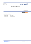
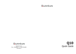
FLOPURGE
User manual rel. 1.0
May 2003
Messer Cutting & Welding GmbH
Lärchenstr. 139a - 65933 Frankfurt / Main – Germany
Tel. +49-(0)69-38016-226 ∗ Fax +49-(0)69-38016-200
TABLE of CONTENTS
PREVIEW ................................................................................................................. 3
INSTALLATION...................................................................................................... 3
Earth ................................................................................................................... 3
Backup battery .................................................................................................... 3
KEYBOARD OPERATION .................................................................................... 4
CYLINDER REPLACEMENT SEQUENCE ............................................................. 5
MANUAL OPERATIONS ..................................................................................... 6
PROGRAMMING .................................................................................................. 6
System ................................................................................................................. 6
Input setup .......................................................................................................... 7
Valve V control ................................................................................................... 9
PASSWORD........................................................................................................... 9
FUNCTIONS........................................................................................................... 10
MONITORING ......................................................................................................... 10
ALARMS MANAGEMENT ......................................................................................... 10
FAILS ..................................................................................................................... 11
REMOTE ALARM .................................................................................................... 11
SHUT-OFF .............................................................................................................. 11
HALT ..................................................................................................................... 12
RESETTING ALARM THRESHOLDS ........................................................................... 12
ERASING SETUP PARAMETERS ................................................................................ 12
MOUNTING ........................................................................................................... 13
ELECTRICAL CONNECTIONS ......................................................................... 14
TYPICAL APPLICATIONS ................................................................................. 15
TECHNICAL CHARACTERISTICS................................................................... 16
2
PREVIEW
FLOPURGE manages four 4-20mA inputs, ten ON/OFF inputs with
alarm and shut-off alarm functionality and four solenoid valves. Every inputs
can be configure as alarm or shut-off event. The measurements 4-20mA and
possible alarm or shut-off events are shown in real time on display 4x20
characters. Every shut-off event causes the immediate switch off of all
solenoid valves. FLOPURGE automatically controls the solenoid valve of
process gas (V3 or V3+V) and two solenoid valves for purging cycles (V2,
V4).
INSTALLATION
The FLOPURGE housing is an IP 55 wall mounting plastic box.
Outside installation must be protected from direct sun and rain.
Technical information concerning cabling, mounting and further details
are shown in the outlines at the bottom of the manual.
Earth
FLOPURGE unit needs an earth connection to protect the circuitry
from surges, due to electrical discharges coming from power and phone
networks (see connection layout).
To safeguard the equipment from over-voltages and for safety
reasons, the earth connection must always and obligatorily exist.
The manufacturer denies all responsibility for whichever damage to
people and things, including equipment, caused by fault of earth connection.
Backup battery
A NiCd backup accumulator, disconnected at the delivery, maintains the
data in memory and real time clock function during thirty days about.
Turn ON the switch labeled BATTERY, located in the rear of the front
panel, to connect the backup battery before the first power-up.
3
KEYBOARD OPERATION
Programming, reading and command functions are performed by four
keys on front panel, through a series of menus.
PASSWORD
Pushing Ö over tree seconds, the system
will require the password to enter into
programming mode.
Push Ø × to select desired digit, Õ Ö to modify it.
PASSWORD
000
REPLACE CYLINDER
MANUAL
SET-UP
EXIT
MAIN MENU
After entering the keyword, push Ö to
open the MAIN MENU and activate the
programming mode.
In programming mode, the keys assume following functions:
Ø×
• selecting options and menus
• scroll pages pertaining to same menu
• return to upper menu
ÖÕ
• entering into selected menu
• setting variables values and alphanumeric characters
• setting options
System disables keyboard functions and returns in running mode
selecting the exit option from main menu, or by keyboard time-out of 30
seconds.
4
CYLINDER REPLACEMENT sequence
By the Replacing Cylinder sequence, the system interacts with operator
step by step and automatically performs purging cycles, to avoid releasing
dangerous gases in ambient and introducing contaminants into supply line.
REPLACING CYLINDER 1
Step 1 – Selecting the option REPLACE
CLOSE V (1)
OPEN WASTE GAS LINE CYLINDER from MAIN MENU, system
2
∨ abort
continue ∧ automatically closes V3 and V ( ), the page
left appears on display. Push key Ø to
abort the sequence, or perform the manual operations suggested on display
and then push × to continue.
REPLACING CYLINDER 2
Step 2 – System starts the first purging
PURGING
sequence (purging); display shows current
V2:[s] V4:[s] C:
status of V2 and V4, and remaining cycles to
the end of the purging sequence.
REPLACING CYLINDER 3
Step 3 – Page left will appear on display
REPLACE CYLINDER
WEIGHT: .... Kg
at the end of first purging sequence.
TARE:
.... Kg
∧ Replace the empty cylinder and then push ×
to continue. In case the gas provision is
detected by electronic scale, the display shows the current weight, so that
the user can set the tare of the new cylinder using Ö Õ. Push × to pass into
next step.
REPLACING CYLINDER 4
Step 4 – System starts the second
PURGING
V2:[s] V4:[s] C:
purging sequence (washing); display shows
same information of step 2.
REPLACING CYLINDER [5
Step 5 – At the end of second purging
CLOSE WASTE GAS LINE
sequence, the page left appears on display.
OPEN V (1)
end ∧ Perform the manual operations suggested on
display and then push × to end.
Push × to end the sequence and return to MAIN MENU: system
automatically opens V (2) and V3.
(1) – messages appearing if V CONTROL = Manual only (see forward)
(2) – actions occurring if V CONTROL = Flopurge only (see forward)
5
MANUAL OPERATIONS
Selecting MANUAL option from the MAIN MENU, you can transfer the
control of the valves from the system to the keyboard.
V :[s]
V3:[s]
EXIT
MANUAL
V2:[s]
V4:[s]
SYSTEM CONTROL MODE
V does not appear with VALVE V CONTROL set
to MANUAL (see previous paragraph).
Automatic / Manual
Select this option and press the buttons Õ Ö to change the control of the
system from automatic to manual mode and vice versa.
Leaving the system in manual mode, the message MANUAL CONTROL
MODE will appear cyclically on display.
[s]
Field indicating the current status of the corresponding valve.
Select the valve and press the buttons Õ Ö to change the status from
ON to OFF and vice versa.
PROGRAMMING
SYSTEM
INPUT
VALVE V CONTROL
PASSWORD
PURGING CYCLES:
VALVE ON TIME:
BUZZER VOLUME:
RECOVERY TIME:
6
SET-UP MENU
System goes into programming menu after
selecting SET-UP option from MAIN MENU and
pushing Ö.
System
This menu allows defining purging parameters,
alarm volume and alarm recovery time.
Purging cycles
This field sets the total number of cycles before disconnecting an empty
cylinder or after connecting a new cylinder. Each cycle include two phases:
charging nitrogen (V4 open) and discharging waste gas (V2 open)
Valid range is from 1 to 99.
Valve ON time
This field sets the duration of the single phase, equal for the charge and
the discharge phases.
Valid range is from 1 to 99 seconds.
Buzzer volume
The variable defines the buzzer volume: valid settings are numeric values
from 1 to 10 and the OFF option, corresponding to buzzer disabled.
Recovery time
This function reactivates the acoustic signal and resends the
acknowledged alarm status into the unacknowledged condition, if this
persists longer than the recovery time.
Valid range is from 0 to 99 minutes and the option OFF, which disables
the recovery function.
Input setup
The menu allows defining all parameters concerning analog and digital
inputs.
4/20 mA INPUT
1 2 3 4
Push Ø and × to move the cursor on the desired
ON/OFF INPUT
1 2 3 4 5 6 7 8 9 10 input; Ö to select it.
4…20 mA INPUT CONFIGURATION
Page # 1: MEASUREMENT
IN1 4/20mA CNF
ID:
........
Unit:
...
Zero: ... FS: ...
Page # 3: ALARM
IN1 4/20 mA CNF
ALARM THRESHOLD
MIN:
MAX:
MODE:
7
IN1 4/20 mA CNF
TARE:
DELAY:
Page # 2: Tare / Al delay
Push Ø and × to move the cursor on the desired
field; Õ and Ö to edit the value / option
Page 1: MEASUREMENT
Identifier (ID)
Alphanumeric string defining the measurement associated to the input,
with maximum length 8 charters.
Warning !!
• Input results configured and enabled if first character of corresponding ID
is different from (blank).
Unit
Units of measurement associated to the input.
Following options are available: bar, mb, Kg, ton, %, ppm.
Zero – FS (Full Scale)
Limits of range of the transducer, defined with measurement units
selected in measurement unit.
Zero and FS values correspond to the measurements supplied by the
analog transducer when the output current is respectively 4 and 20 mA.
Valid range is 0.0 ÷ 999.
Page 2: TARE/DELAY
Tare
Define the weight corresponding to the conditions: storage completely
empty expressed in Kg.
The field appears when unit is set to Kg only.
Delay
Minimum duration of the alarm condition before generating the alarm
status, expressed in seconds.
Alarm conditions correspond to:
• input signal outside alarm thresholds, for analog inputs
• input signal different from normal status, for digital inputs
Valid range is 0 to 99 seconds.
8
Page 3: ALARM
Min, MAX
Minimum and maximum alarms thresholds.
Values must be set within the interval Zero – FS.
Mode
Function associated to the input.
ALARM
the active status of the input generates ALARM status
SHUT-OFF
the active status of the input generates SHUT-OFF status
IN 1 ON/OFF CNF
ID............ NO/NC
DELAY:
MODE:
ON/OFF INPUTS CONFIGURATION
Push Ø and × to move the cursor on desired field;
Õ and Ö to edit it.
NO/NC
Status of the sensor associated to the normal conditions (non-alarm or
non-active): NO as normally open, NC as normally closed.
For remaining fields refer to previous paragraph analog inputs
configuration.
Valve V control
VALVE V CONTROL
V: FLOPURGE CONTROL
This menu allows including or excluding the
valve V from the system management, in
function of the valve type: solenoid or manual.
Available options are FLOPURGE CONTROL and
MANUAL.
PASSWORD
This option allows setting and modifying the password.
Push Ø × to select desired digit, Õ Ö to modify it.
Warning !! - Password authentication is skipped setting the keyword to 000.
9
FUNCTIONS
Monitoring
In absence of alarm, shut-off and halt status, the display shows the status
page, containing all measurements related to the configured inputs 4/20 mA.
ID
ID
ID
ID
An.1
An.2
An.3
An.4
value
value
value
value
1
2
3
4
un1
un2
un3
un4
Typical status page
Example left shows the typical status page
including all analog inputs, where the fields
identifier and un were still explained in
previous section programming, and value indicates the current value of the
measurement.
In case no setup parameter is defined (first power-up) or no analog input
is configured, the status page assumes following shapes:
First power-up
FLOPURGE
NO SETUP PARAMETER
No configured analog inputs
FLOPURGE
NO ALARM
Alarms management
Alarm page management differs from monitoring of status pages due to
following details:
• When an alarm status begins, the display shows a blinking page
containing alarm information (alarm page), until the acknowledgement
operation;
• After the acknowledgement, the display alternates the status page to the
blinking alarm page in sequence, with refresh period 5 seconds.
The acknowledgement of the alarm page occurs by pushing the ACK
pushbutton on front panel when this appears on display.
When more than four alarms are in progress, these are shown by more
alarm pages, each requiring a distinct ACK (acknowledgement sequence); in
this case, the display will resume the cyclical visualization of status page and
alarm pages after completing the acknowledging sequence.
In case a new alarm goes active when all current alarm pages are
acknowledged, the display stops on alarm page showing new information.
10
Whichever acknowledged alarm status persisting longer than the
recovery time automatically returns into the unacknowledged condition and
requires a new cumulative acknowledgement operation (only one for all
alarms pages).
The acoustic signal continues until unacknowledged alarm pages exist.
The red light signal remains alight until the alarm status exists.
Typical ALARM PAGE
Ident.1 value 1 un1
Ident.2 value 2 un2
Ident.3
The example left shows an Alarm Page including
alarms by analog transmitters and switch
sensors.
Fails
FLOPURGE periodically performs a self-test to recognize possible fails.
The system fails are classified and monitored as alarms, and include:
Fail message or signal
Sensors power fault
Valves power fault
ID1…4
--- un
Slow blinking of
fault red led
Fail origin
Onboard auxiliary power supply
24Vdc auxiliary power supply
Transmitter 1…4 disconnected
Electronic system
Effects
All inputs out of order
Solenoid valves out of order
Signal out of range
System fault
Remote alarm
Remote alarm output is a relay output available on screw connector CN2.
Output relay is energized when system is in Alarm, Shut-off or Halt
status.
Shut-off
The shut-off status is an additional alarm condition that interrupts the gas
supply, by closing V and V3.
Each input classified as shut-off also generates alarm status; for this
reason, the shut-off status is notified like an alarm status, adding the suffix
EMO to the ID of each shut-off input that have generated it, and by the fastblinking of the red alarm light.
11
Differently from the alarm, the shut-off status requires a manual restoring
and the shut-off status events are managed “with memory”.
That means the alarm monitoring continue until the ACK, even if the
event is already terminated, and only when all events are closed and
acknowledged the system enters into HALT status.
Halt
The Halt status always occurs after SHUT-OFF or the
testified by the yellow light signal blinking.
POWER-UP
and is
SYSTEM HALTED
UP Key:
SUPPLY
DOWN Key: MANUAL
During the HALT status, V and V3 remain
close; the display suspends the scrolling
functions and shows following message.
Press Ø or × to exit from HALT status and enter into manual or automatic
mode.
Resetting alarm thresholds
Whilst FLOPURGE is operating, push the push-button behind the front
panel, until the message erasing appears on display.
This operation, effective over all analog inputs, sets to Zero the minimum
alarm thresholds and sets to Full Scale the maximum alarm thresholds.
Erasing setup parameters
Setup parameters are stored in a non-volatile memory and retained also
in power-off condition, without time limits.
If you like to erase all current setup parameters and set them to default
values, observe following sequence of operations.
1. Disconnect the power supply;
2. Push and hold the button behind the front panel, close the battery switch;
3. Connect the power supply;
4. Release the pushbutton when the message erasing appears on display.
This operation set all input ID = blank (all inputs disabled), V = manual,
Purging cycles = 5, Valve ON time = 3 seconds, Buzzer volume = 10,
Recovery time = OFF.
12
MOUNTING
Mounting tools
Drilling layout
# 4 Ø 6 mm expansion nails
220 mm X 160 mm
13
ELECTRICAL CONNECTIONS
CN7
CN5
CN6
CN1
CN2
CN11
4…20 mA analog inputs
Digital inputs from 1 to 5
Digital inputs from 6 to 10
Solenoid valves control
outputs alarm relay
220Vac power supply
CN7
Analogs 4…20 mA
Pin
Input
1
+ AN 1
2
– AN 1
3
+ AN 2
4
– AN 2
5
+ AN 3
6
– AN 3
7
+ AN 4
8
– AN 4
9
COM 10
ground
CN5
CN6
Digitals 1– 5
Pin
Input
1
+D 1
2
–D 1
3
+D 2
4
–D 2
5
+D 3
6
–D 3
7
+D 4
8
–D 4
9
+D 5
10
–D 5
Digitals 6– 10
Pin
Input
1
+D 6
2
–D 6
3
+D 7
4
–D 7
5
+D 8
6
–D 8
7
+D 9
8
–D 9
9
+ D 10
10
– D 10
CN2
Relay output
Pin
Output
1
14
COM
2
NC
3
NO
CN1
Solenoid valve controls
Pin
Signal
Type
1
V 1 (+)
OUT
2
V 2 (+)
OUT
3
V 3 (+)
OUT
4
V 4 (+)
OUT
5
-reserved
6
-reserved
7
24 V (+)
IN
8
24 V (+)
IN
9
24 V (–)
IN
10
--reserved
TYPICAL APPLICATIONS
ANALOG SENSORS
DIGITAL SWITCH SENSORS
Warning ! !
• Pins 2 – 4 – 6 – 8 – 10 of screw connectors CN5 e CN6, labeled by– D,
are interconnected on FLOPURGE board.
• Do not connect external power supply to switch sensors
15
TECHNICAL CHARACTERISTICS
4…20 mA Analog Inputs
Compatibility
Maximum voltage (open circuit)
Minimum voltage @ I = 20 mA
Short circuit current
Resolution
4...20 mA transmitters
24 Vdc
16 Vdc
25 mA
10 bit
Digital Inputs
Compatibility
Maximum voltage (open circuit)
Short circuit current
Switch sensors
15 Vdc
15 mA
Alarm relais output
Maximum switching voltage
Maximum switching current
250 Vac / Vdc
100 mA
Power supply
Supply voltage
Maximum supply current
220 Vac – 50 Hz
100 mA
Valves driver outputs
Nominal voltage
Maximum switching current
Insulation voltage
24 Vcc
100 mA
> 4 KV
Mechanical protection degree
IP 55
Art.-no. 770.51675 Rev. 0053
16