1
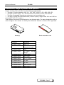
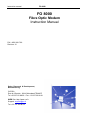
Instruction manual
FO 8000
FO 8000
Fibre Optic Modem
Instruction Manual
P/N : 8000 601 786
Revision 10
Sales, Research & Development,
Manufacturing :
CXR SA
Rue de l'Ornette - 28410 Abondant FRANCE
Tel +33 237.62.88.00 - Fax +33 237.62.88.01
WEB Site: http://www.cxr.fr
Support: [email protected]
Tel: +33 237.62.88.04
Instruction Manual
FO 8000
Warning :
No part of this document should be reproduced transmitted or translated without written
authorization from CXR S.A
All rights reserved. Copyright 2005, CXR SA, Printed in France, 2006 May.
The only purpose of this manual is to provide information and installation instructions
CXR reserves the rights to improve its products and specifications without notice.
CXR has made every effort to provide the best possible quality in writing this manual but cannot
be held responsible for any damage, which could result from errors or improper description of
the equipment, its characteristics and operation.
Please read and enforce the safety instructions of the safety and installation chapters.
The team at CXR Anderson Jacobson thanks you for choosing
the FO8000 Fibre Optical Modem
We hope that this equipment will provide full satisfaction and in order to serve you even better,
we thank you for returning the warranty card you will find at the end of this manual.
We also invite you to read the last part of this manual, which provides useful information on the
warranty terms and conditions, which apply to your equipment.
FO 8000 - Page 2
Instruction Manual
FO 8000
Content
1.
INTRODUCTION .................................................................................9
1.1.
1.2.
1.3.
2.
FIBRE OPTIC LINK...........................................................................10
2.1.
2.2.
2.3.
2.4.
2.5.
3.
LAN TO LAN CONNECTION .............................................................16
LAN TO LAN CONNECTION VIA FIBRE AND E1/E1 NETWORK ............16
LAN TO LAN BRIDGING ..................................................................16
V28 ASYNCHRONOUS OR SYNCHRONOUS INTERCONNECTION ...........17
E2, E1 OR 4E1 PBX, DATA INTERCONNECTION ..............................17
TERMINAL ADAPTER TO PBX TRANSPORT .......................................18
CLOCK MODE.................................................................................18
OPERATION AND CONFIGURATION............................................20
5.1.
5.2.
5.3.
5.3.1.
5.3.2.
5.3.3.
5.3.4.
5.3.5.
5.3.6.
5.4.
6.
LED DISPLAY .................................................................................14
THE PUSH BUTTON .........................................................................15
TYPICAL APPLICATIONS ...............................................................16
4.1.
4.2.
4.3.
4.4.
4.5.
4.6.
4.7.
5.
MULTI-MODE FIBRE ........................................................................10
SINGLE-MODE FIBRE ......................................................................10
CALCULATION OF THE BUDGET AND FIBRE DISTANCE .......................11
DESKTOP VERSION .........................................................................11
RACK MOUNT VERSION ...................................................................12
FRONT PANEL, DISPLAY ...............................................................14
3.1.
3.2.
4.
DTE INTERFACE ..............................................................................9
CONDITIONING ...............................................................................10
CONFIGURATION ............................................................................10
CONFIGURATION SOFTWARE MXCFG ..............................................20
FACTORY AND USER CONFIGURATIONS ...........................................21
VT100 INTERACTIVE MENUS .......................................................... 21
Menu 1 : Configuration ................................................................................................ 23
Menu 1.2 : Edit a configuration (except FO8011 option 96 and FO80E2).................... 24
Menu 1.2 FO8011-96, FO80E2: Edit a configuration ................................................... 26
Menu 2 : Status and statistics ...................................................................................... 27
Menu 3 : Loop Test...................................................................................................... 27
Menu 4 : Display and passwords ................................................................................. 28
REMOTE CONTROL .........................................................................28
DIAGNOSTICS AND TESTS ............................................................29
6.1.
6.2.
6.2.1.
6.2.2.
DIAGNOSTICS .................................................................................29
TEST ............................................................................................. 30
Local Analog Loop ....................................................................................................... 30
Remote Digital Loop .................................................................................................... 31
FO 8000 - Page 3
Instruction Manual
FO 8000
7.
MEMORY...........................................................................................32
8.
TECHNICAL CHARACTERISTICS ..................................................33
8.1.
8.2.
9.
TRANSMISSION MODES ...................................................................33
GENERAL CHARACTERISTICS ..........................................................34
TROUBLESHOOTING ......................................................................35
9.1.
10.
POWER UP .....................................................................................35
APPENDIX......................................................................................36
10.1.
10.1.1.
10.1.2.
10.1.3.
10.1.4.
10.1.5.
10.1.6.
10.2.
10.2.1.
10.2.2.
10.3.
APPENDIX A – WIRING ................................................................ 36
Serial Control Port - RJ45........................................................................................ 36
RJ45 - Line connector.............................................................................................. 36
10 Base T Interface connector................................................................................. 37
X21/V11 and V35 Interfaces connector & wiring..................................................... 38
X21/V11 Option 96 Interfaces connector & wiring ................................................... 39
BRI Interface RJ45 ............................................................................................... 40
APPENDIX B - JUMPERS CONFIGURATION ..................................... 41
DIP SWITCH position on daughter card FO8xBR................................................... 41
DIP SWITCH position on daughter card FO80E2 ................................................... 43
APPENDIX C : WARRANTY, GENERAL CONDITIONS......................44
FO 8000 - Page 4
Instruction Manual
FO 8000
Convention, range of product and options
Several versions of the unit differ from the following characteristics:
The type of Terminal interface: V28, V11, V35, 10BT, HUB, E1, 4E1, 4BRI, 2BRI, E2
The type of power supply: 110 / 230 Vac internal or external, 48 Vdc, 5Vdc external
The type of packaging: stand alone enclosure or rack mountable card
The type of optical Fibre: Multimode 820 (1300 nm option), Single mode 1310 and 1550 nm
connector ST ( SC, FC in option )
These different versions are summarized on the following table. The same designations will be
used throughout this manual to identify the differences between versions when applicable.
Rack mountable card
Desktop
Version
Interface
FO 8011-mmcz
X21-V11
FO 8011-mmcz-96
X21-V11
transparent mode
FO 8035-mmcz
V35
FO 80BT-mmcz
10 BaseT filtering
bridge
FO 80HB-mmcz
Hub 4 ports
FO 80E1-mmcz
E1 / G704
FO 84E1-mmcz
4 * E1 / G704
FO 82BR-mmcz
2 * BRI
FO 84BR-mmcz
4 * BRI
FO 8028-mmcz
V28 / RS232
FO 80E2-mmcz
E2 / G703
FO 8000 - Page 5
The variants mmcz are:
Variant
Multimode 820 nm
Multimode 1300 nm (option)
Single mode Led 1310 nm (ST connector
only)
Single mode Laser 1310 nm
Single mode Laser 1550 nm
Connector SC (option)
Connector ST®
Connector FC (option)
External power supply 5 Vdc
Internal power supply 90 – 240 Vac
Internal 48 Vdc converter
Rack mount card AMS16
MM
M8
M3
SL
Z3
Z5
C
Z
C
T
F
V
I
C
R
ST® is a registered trademark of AT&T
Default connector is ST . ( SC and FC in option )
Example: The FO 8011 M3CI-E is a desktop version with internal 110 / 230 Vac power supply
that provides an X21-V11 DTE interface DTE, fibre optic is Multimode at 1300 nm with SC
connector in Export version.
X21-V11 and V35 cables are available as an option:
•
V35: CXR reference CA.601.460
•
X21-V11 (DB15): CXR reference CA.601.461
Important Information
Conformity Statement EC
Manufacturer name:
CXR
Manufacturer address:
rue de l'Ornette - 28410 ABONDANT - France
States that:
Product name:
FO 8000
Complies with the following specifications:
Safety:
EN 60950
EMC:
EN 55022: - Class B
EN 50082-1
The CE marking on this product indicates that it complies with 99/5/CE order dated April 7-1999
FO 8000 - Page 6
Instruction manual
FO 8000
Safety Instructions
The following accesses are referenced as SELV (Safety Low Voltage] in conformity with
EN.41003 standards:
•
•
•
•
•
•
•
•
•
•
5 VDC Input of the FO 8000 desktop unit
48 VDC Input of the FO 8000 desktop unit
Control: V24 - RS232 configuration port
DTE - V11: V11-X21 interface of the FO 8011 unit
DTE - V28 : V28 interface of the FO8028
DTE - V35 : V35 interface of the FO8035
DTE - 10BT : Ethernet interface of the FO80BT
DTE - HUB : 4 port HUB Ethernet interface of the FO80HB
DTE - E1 : E1 G 704 interface of the FO80E1
DTE - 4E1 : four E1 G 704 interfaces of the FO84E1
•
•
DTE - BRI: 2 or 4 ISDN S interface of the FO 82BR or FO 84BR unit
DTE – E2 : E2 G 703 interface of the FO80E2
Desktop FO 8000 V:
The wall mount power supply adapter is the main switching element. Thus this plug must be
installed close to the equipment and provided easy access.
To totally disconnect the equipment from the supply source we recommend you disconnect the
power cord from the mains wall outlet. In order to comply with the safety regulations, it is
imperative to use the accessories (power supply and cables) provided with the equipment. When
access to the inside of the modem is necessary, it is imperative to disconnect the power adapter
from the mains outlet.
Desktop FO 8000 I :
The power cord is the main switching element. Thus the mains outlet must be installed close to
the equipment and provided easy access. In order to comply with the safety regulations, it is
imperative to use the accessories (power supply and cables) provided with the equipment. When
access to the inside of the modem is necessary, it is imperative to disconnect the power cord from
the mains outlet. This is a Class 2 product as shows the
symbol close to the mains socket; its
earth connection is for functional purpose only.
Rack mountable card FO 8000 R:
The power switch located on the rear of the chassis is the only switching element, thus it must be
fully accessible. The connection to the mains is achieved through the cable equipped with a malegrounded plug. Extract the card from the chassis when maintenance or servicing is required
For safety reasons, any operation on the equipment and particularly opening the desktop
enclosure must be carried out by maintenance person qualified by CXR.
The equipment must imperatively be returned to CXR in any case of anomaly, fall, loss of
performance, water exposure, power supply damage, …
Optical Fibre:
Class 1 Product
WARNING: Do not look directly into the aperture
of the transmitting diode or the optical fibre.
The light beam which is emitted could cause
permanent damage to your eyes.
FO 8000 - Page 7
Environment
The FO 8000 is designed for residential or light industrial use within the following environmental
conditions:
•
•
•
•
•
•
•
Storage Temperature
0 to 70 °C
Operating Temperature:
0 to 45 °C
Hygrometry:
0 to 90% without condensation
Class:
IP40
Flammability:
UL94-V0
Equipment must not be exposed to excessive solar radiation
Equipment must not be in contact with water. It must not be used near a water reserve or in a
wet location.
Use
The FO 8000 is designed to be connected to a DTE G703/G704 compatible network or to a to an
X21-V11 or V35 or V28 or to an Ethernet 10BT equipment.
•
Nx64 KBPS DTE interface : from 64 KBPS to 2048 KBPS
•
X21 and V35 DTE interface :
from 64 kBps to 2048 kBps by step of 64k
and 4096, 6144, 8192 kBps
•
X21-V11 option 96:
Transparent mode from DC to 8448 MBPS
External clock from DTE. Both FO8011 are co directional.
External clock from DTE and Network clock to remote. Not codirectional, only one
clock source.
•
V28 – RS232 interface :
asynchronous up to 115200 Bps
synchronous up to 128000 Bps
•
Ethernet bridge and 4 port Hub :
Ethernet 802.3
Frame buffer : 256
Mac address memory : 10.000
•
Interface E1 and 4E1 G703-G704:
rate G703: 2048 Kbps +/- 50ppm
coding: HDB3
framing: 32 Time Slots - G704 compatible
receiver sensitivity: -40 dB
•
Interface E2 G703:
rate G703: 8448 +/- 20 ppm ( also operational at 2048 Kbps +/- 50ppm )
coding: HDB3
receiver sensitivity: -10 dB Short Haul
•
BRI interface:
2 or 4 ISDN S interface
Network or Terminal interface
FO 8000 - Page 8
Instruction manual
FO 8000
Fibre Optic Link :
Multimode 62.5/125µm 820 nm: budget 15 dB i.e. 4 kms @ 3dB/kms
Multimode 62.5/125 µm 1300 nm : budget 12 dB i.e. 8 kms @ 1.5dB/kms (option)
Single mode 9/125 µm 1310 nm Led : budget 14 dB i.e. 40 kms @ 0.35 dB/kms
Single mode 9/125 µm 1310 nm Laser : budget 23 dB i.e. 65 kms @ 0.35 dB/kms
Single mode 9/125 µm 1550 nm Laser : budget 29 dB i.e. 120 kms @ 0.23 dB/kms
Correct Disposal of the Product - Recycling
In compliance with the European rules for separate collection systems and
Waste of Electric and Electronic Equipment, this marking shown on this
product indicates that it should not be disposed with other household wastes
at the end of working life. To prevent possible harm to the environment or
human health from uncontrolled waste disposal, please separate this from
other types of wastes an d recycle it responsibly to promote the sustainable
reuse of material resources.
Household users should contact either the retailer were they purchased this product, or their local
government office for details of where and how they can take this item for environmental safe
recycling.
Business users should contact their supplier and check the term and conditions of the purchase
contract. This product should not be mixed with other commercial wastes for disposal.
1.
Introduction
The FO 8000 is a fibre optic modem with different DTE interface X21/V11, V35, V28, 10
BaseT, E1, 4E1 (2048 KBPS), E1 (8448 KBPS) or 2BRI or 4BRI (2 or 4*192 KBPS) network
access.
1.1.
DTE Interface
The FO 8000 can be equipped with different types of interface:
X21/V11 or V35 interface: for synchronous data transmission at speed of up to 8192 KBPS.
Clock can be configured as internal, external or slaved. Most interface signals can be forced
or activated when the connection is established.
X21/V11 option 96: for synchronous data transmission at speed of up to 8448 KBPS.
When clock is in external mode and both local and remote FO are codirectional, the clock value
must be very different, like 4096 kbps in upstream and 175 kbps in downstream. Most interface
signals can be forced or activated when the connection is established.
When clock is not codirectional, one FO8011 must be in external mode (DTE) and the remote
must be in network clock mode.
V28 interface: for synchronous data transmission at speed up to 128000 Bps, for
asynchronous data up to 115200 Bps. In synchronous mode clock can be configured as
internal, external, or slaved. Most interface signals can be forced or activated when the
connection is established.
10BT interface and HUB 4 ports: The built-in Ethernet bridge filters the frames in accordance
with their destination MAC address. Only frames with non-local MAC addresses are
transmitted to the remote unit. The bridge can memorize up to 10.000 local addresses and
process 15.000 frames per second.
E1 Interface: for E1 G703 or G704 network access at 2048 kBps. Clock can be configured as
internal, external or slaved.
4E1 Interface: for four E1 G703 or G704 network access at 2048 kBps. Clock can be
configured as internal, slaved or external ( 1 of 4 DTE port ).
BRI interface: to transport 2 or 4 ISDN S interfaces.
FO 8000 - Page 9
E2 Interface: for E2 G703 at 8448 KBPS ( or E1 G703 2048 KBPS ). Clock is always in
external mode. The local and remote FO80E2 are co directional, the clock value must be
different.
1.2.
Conditioning
The FO 8000 can meet all integration requirements either as a desktop or rack-mount unit with
different power-supply configurations
External power bloc: provides a regulated 5 VDC from the mains 110/230 VAC
Internal power supply: the modem includes a 110/230 VAC - 5 VDC power converter which
connects directly to the mains outlet via the supplied power cord
Internal 48 VDC converter: the modem includes a 48 VDC power converter, which can be
connected to a 48Vdc supply commonly available in telecom centers.
Rack-mountable card: the 5 VDC required by the modem is supplied by the rack in which the
card is inserted. The AMS 4 and AMS 16 chassis can be powered from 110/230 VAC or 48
VDC depending on the type of power module installed with provision for full redundancy
1.3.
Configuration
The FO 8000 is configured via the serial control port set for VT100 emulation at 19200 BPS with
data format of 8 bits, parity none.
The configuration is menu driven with on line help facilities. Only a few keyboard strokes will be
required to set and save the FO 8000 parameters. These menus also initiate analog and digital
test loops and display a status report and a bit error rate statistics.
Alternatively the modem can be configured using an AT command set which provides access to
all modem parameters.
The FO 8000 card can also be configured by the CFIP controller card of the AMS16 chassis
though its local VT100 mode or TCP-IP Telnet and SNMP management protocols
2.
FIBRE OPTIC link
The FO 8000 supports two different fibre optic type : multi-mode or single mode fibre.
2.1.
Multi-mode Fibre
This is the classic fibre optic cabling, the most commonly installed core is 62.5 micrometers and
outer cladding size is 125 micrometers. The FO 8000 component are compatible with 62.5 and 50
micrometers core.
In multi-mode fibre, the FO 8000 uses two different wavelengths the 820 nanometer and 1300
nanometer. These wavelengths allow distance up to 8 kms between two FO8000.
In multi-mode fibre at 820 nanometer, the modal dispersion is not negligible, but the limit is
greater than the fibre attenuation.
The attenuation of the beam is more important in the 820 nanometer than in the 1300 nanometer.
All the calculation of the budget and fibre distance are described in the next paragraph.
Typically the multi-mode fibre is orange.
2.2.
Single-mode Fibre
Single-mode fibre uses a smaller core diameter of 9 micrometer and the cladding size is also 125
micrometer.
FO 8000 - Page 10
Instruction manual
FO 8000
In single-mode fibre the FO 8000 supports also two different wavelength component, the first is
1310 nanometer and the second is 1550 nanometer.
The attenuation is close to the theoretical attenuation at 1550 nanometer.
Typically the single-mode fibre is yellow.
2.3.
Calculation of the Budget and Fibre Distance
The F8000 is defined by the DTE Interface and the Fibre Optic Budget at the different wavelength.
The Fibre Budget is the difference between the receiver sensivity and the transmitter power.
On each wavelength, a fibre attenuation per kilometer is defined.
Between the two FO 8000 there are some connectors and splices.
The connector attenuation is 1 dB, and splice attenuation is 0.05 dB.
A buffer is added into the calculation ( 2 dB ).
Distance = (Fibre Budget) – (Splice Loss) – (Connector Loss) – Buffer
(Fibre Attenuation)
Example: In multimode fibre at 820 nm the attenuation is 3dBm/km, with two connectors (2 dB)
and one splice (0.05 dB), the Fibre Budget of FO 8000-M8 is 15 dB.
Distance = 15 – 0.05 – 2 – 2 = 3.6 km (with margin)
3
Example: In monomode 1310 nm attenuation is 0.3 dBm/km and the FO 8000-SL budget is 23 dB
Distance = 14 - 0.05 – 2 – 2 = 33 km
0.3
This calculation is realized with the above values, but the actual loss in the fibre is better
measured once the fibre is installed, generally it is impossible to know the number of connectors
and splices.
2.4.
Desktop version
Accessories
•
•
•
•
•
One RJ45-RJ 45 cable and one RJ45-DB9 converter (P/N: 7055031517) for the control port
External power supply module when applicable .
One DB25-DB15 cable as an option of the X21-V11 interface FO8011 version
(P/N:CA601461).
One DB25-V35 cable as an option of the V35 interface FO 8035 (P/N:CA601460).
This user Manual
Connection
•
•
•
•
Connect the modem as per the following drawing. View is from the rear.
Ensure that the end face of the optical plugs are clean.
Connect the fibre optic ( type ST, SC, FC ) : ensure that the optical input Rx and output Tx are
connected to the other unit ( crossover connection ).
The DTE terminal connector depends on the type of interface:
o
A DB25 socket for V28-RS232, X21-V11 and V35 interfaces,
FO 8000 - Page 11
o
o
o
o
o
An RJ45 socket for 10BT, E1, E2.
Two BNC for E2 and E1 interface in option (Transmitter near the fibre, Receiver near the
power connector)
Four RJ45 socket for 4E1 interface.
Four RJ45 for the HUB interface.
Four RJ45 for the 2BRI or 4BRI interface.
Rear panel
CONTROL FO TX RX
TERMINAL
OFF ON
DTE interface
SELV
110/230V
Control
V24.RS232
SELV
Another FO8000
RX<->TX crossed
TX<->RX crossed
(*) 110/230VAC / 5VDC Wallmount power supply or 110/230VAC or 48 Vdc cable as applicable.
(*) SELV = Safety low voltage
•
For safety reasons it is imperative to use the accessories (power unit and cable) provided with
the equipment.
Powering
The mains adapter / cord is the only switching device and therefore the mains outlet should be
located close to the equipment and easily accessed
Once the FO 8000 has been connected, switch the ON-OFF switch to the « ON » position.
2.5.
Rack mount version
Accessories
•
•
•
•
One RJ45-RJ 45 cable and one RJ45-dB9 converter for the control port
One DB25-DB15 cable as an option of the X21-V11 interface –FO 8011 version (P/N: CA 601
461)
One DB25-V35 cable as an option of the V35 interface –FO 8035 (P/N:CA 601 460)
This user Manual
Installation
•
•
Please also refer to the chassis user manual for the modem installation.
Locate a free slot in the chassis and insert the FO 8000 card.
Connection
FO 8000 - Page 12
Instruction manual
•
•
•
•
FO 8000
Connect the FO 8000 at the rear of the chassis as per the following drawing.
Ensure that the end face of the optical plugs are free of contamination.
Connect the fibre optic ( type ST, SC, FC ) : ensure that one optical input Rx and one optical
output Tx are connected to one another ( crossover connection ).
The DTE terminal connector depends on the type of interface:
o
A DB25 socket for V28-RS232, X21-V11 and V35 interfaces,
o
An RJ45 socket for 10BT, E1, T1.
o
Two BNC for E1 in option, or E2 interface.
o
Four RJ45 for 4E1 interface.
o
Four RJ45 for the HUB interface.
o
Four RJ45 for the 2BRI or 4BRI interface.
DTE SELV
OpticalFiber RX
Optical Fiber TX
Control V24-RS232 SELV
FO 8000 - Page 13
Powering
•
•
The modem card connects to the chassis power supply when it is fully inserted. The chassis is
powered on and off through the rear panel mains switch.
Screw the unit front panel on the chassis to avoid any accidental power or connection loss
3.
Front Panel, Display
This chapter describes the operation of the
6 LED indicators and the push button.
3.1.
LED display
Six LED indicators and one pushbutton are installed on the front panel of the Desktop and rack
mount unit. The LEDs display an indication on the status of the FO8000.
POWER
LED
DTE
SYNC
ERR
DATA
TEST CLR
Function
/ POWER ON when the unit is powered
BLINKING when the unit is powered and the control and
configuration terminal is connected and provides an active DTR-108
signal to the control port
Shows that the terminal equipment is connected. C Signal for V11
DTE
interface, DTR signal for V28 and V35, E1 carrier for E1, E2 carrier
for E2 card, link for 10BT and HUB, 4 carriers E1 simultaneous on
each second for 4 E1 card, 4 synchronized access simultaneous on
each second for 4 BRI card
FO 8000 - Page 14
Instruction manual
LED
SYNC
ERR
DATA
TEST
3.2.
FO 8000
Function
ON when the optical link is synchronized.
BLINKING is case of loss of synchronization.
OFF when optical link is not synchronized.
ON (red) in case of error. (like CRC error or HDB3/B8ZS/AMI code
violation in E1 DTE)
This LED is cleared by the push button (CLR) or by VT100
interface.
AIS detection for E2 card.
Blinking when data are sent or received on the DTE interface.
ON (yellow) when the FO 8000 is in test mode.
The push button
When pushed at power up, it forces the FO 8000 to enter in firmware download mode (Flash
loader). The Power, DTE and TEST LED stay ON in this state.
FO 8000 - Page 15
4.
Typical applications
This chapter describes the basic configuration of the FO 8000 in some typical applications.
4.1.
LAN to LAN connection
Two corporate LAN are connected together throw fibre optic link.
FO8011
FO8035
FO8011
FO8035
……
X21
or V35
……
X21
or V35
Fibre Optic
820,1300 nm Multimode
1310, 1550 nm Singlemode
4.2.
LAN to LAN connection via Fibre and E1/E1 network
Two corporate LAN are connected together through a fibre optic link and an E1 or T1 network
access . The payload may be lower than 2048 KBPS (E1) or 1544 (T1) and provide lower
network access cost (fractional E1 / fractional T1).
FO8011
FO8035
X21
or V35
FO80E1
……
……
FO8035
……
E1/T1 Network
X21 or V35
Fibre Optic
820,1300 nm Multimode
1310, 1550 nm Singlemode
4.3.
LAN to LAN bridging
Two FO 80BT provide an efficient bridging of two Ethernet networks and spare the use of
routers of the previous connection scheme.
10BaseT
10BaseT
……
……
FO80BT
FO80BT
Fibre Optic
820,1300 nm Multimode
1310, 1550 nm Singlemode
FO 8000 - Page 16
Instruction manual
FO 8000
In case of problem or if the Ethernet frame do not comply with the IEEE 802.3 standard then the
following AT parameters could be set on both FO 8000:
*F0: disables the MAC address filtering
*P0: disables the Padding bit deletion
These parameters are modifiable in the menu VT100.
4.4.
V28 asynchronous or synchronous interconnection
To control remotely a serial unit.
RS232
RS232
RS232 Unit
……
……
FO8028
FO8028
Fibre Optic
820,1300 nm Multimode
1310, 1550 nm Singlemode
4.5.
E2, E1 or 4E1 PBX, Data interconnection
Interconnection of one or four E1 equipments with FO80E1 or FO84E1 modem.
E1, E2
PBX
……
……
FO80E1
FO84E1
FO80E2
Router E1
PBX
FO80E1
FO84E1
FO80E2
Fibre Optic
820,1300 nm Multimode
1310, 1550 nm Singlemode
Router E1
With a FO80E2 local, the remote modem can be another FO80E2 or an FO8011 in transparent
mode. The release software must be identical. Speed at 8448 or 2048 KBPS.
FO 8000 - Page 17
4.6.
Terminal Adapter to PBX transport
A pair of FO84BR can transport up to 4 ISDN Basic Accesses. For example four Terminal
Adapters are connected to a remote PBX , through two FO 84BR over a Fibre Optic.
The four B1+B2+D channels are transported. 2 Channels only for the FO82BR.
ISDN-S
Adapter
4 ISDN-S access
Fiber
Fiber
……
……
ISDN
phone
FO84BR
A
4 ISDN-S
access
FO84BR
B
PBX
ISDN-S
Adapter
Timing Consideration
•
If PBX is connected to the public telephone network and gives the master source timing.
The FO84VBR “B” uses this clock and must be in DTE clock mode, then it sends its clock to
the fibre, and the FO84BR “A” must be in Network clock mode. For a new installation, it’s
better to connect the FO84BR B near the PBX in firstly.
4.7.
Clock Mode
The fibre optical modem FO 8000 is used to carry data between two DTE interfaces.
The FO 8000 also carries the clock in most cases.
DTE A
FO 8000 A
Fibre Optic
FO 8000 B
DTE B
A – The DTE A equipment provides the clock in internal mode, and gives it to the FO 8000 and
other DTE B (router V35 / V11, E1/4E1 network, V28-RS232, 4BRI) .
Type DTE A
FO 8000 A
FO 8000 B
DTE B
A
DTE Clock
Network Clock
Receive clock
Internal Clock
FO 8000 - Page 18
Instruction manual
FO 8000
B – Both equipments DTE A and DTE B receive the clock, the FO8000 A generates the clock
for DTE A and transmits it to the other FO 8000 B and DTE B. (router V35/V11, network E1,
V28-RS232, 10BaseT and HUB)
Type DTE A
FO 8000 A
FO 8000 B
DTE B
B
Internal Clock
Network Clock
Receive clock
Receive clock
C – Both equipments DTE A and B gives the clock to the FO 8000 A, B . FO8000 A and B are
in external clock. (E1 and 4E1 with 2 PBX sometimes)
Type DTE A
FO 8000 A
FO 8000 B
DTE B
B
external Clock
external Clock
Internal clock
Internal clock
D – With FO84E1 all the DTE port clock must be isochronous.
E – With FO8011-96 and FO80E2 when the mode is codirectional the clock must be in external
clock mode. The local and the remote FO are co directional. The upstream can be different with
the downstream.
When the clock is not codirectional, one FO8011 must be in external, the other FO8011 must
be in network clock.
Se chapter 10.1.4 and 10.1.5 for signals and explications.
FO 8000 - Page 19
5.
Operation and Configuration
This chapter describes the FO 8000 operation through its Control port.
The FO 8000 must be connected to a VT100 compatible terminal or to a PC running a VT100
terminal emulation software that should be configured as follows:
Speed: 19200 bps
Data format: 8 bits
Parity: none
Stop bit: 1
Emulation: VT100
Flow control: none
The FO 8000 configuration can be made either in AT command mode or VT100 Interactive
menu mode. The choice of mode is automatic: the AT command mode is activated when an
“AT” or ”at” character string is received from the control port. The VT100 menu mode is started
when the modem detects three consecutive carriage returns or “ENTER” characters.
The use of the VT100 mode offers valuable advantages such as simplicity and on line help.
The use of the AT commands allows writing configuration programs which can be saved out of
the unit on a PC for instance and can also be protected with a password.
All the FO 8000 operation parameters can be modified and saved in either mode.
The detail of the AT command is described in another document. ( Ref CXR : 8000 601 836 )
5.1.
Configuration Software MxCfg
The configuration software Mxcfg allows:
•
See the current configuration of FO8000
•
Modify the parameters
•
Save the new parameters
•
The all the parameters in a file on your Laptop
•
View the diags
Mxcfg run under Windows 95/98/NT/2000/XP.
To install Mxcfg, type “a:\Setup.exe” on the floppy disk or “\tools\french\mxcfg\setup.exe" on the
CDROM.
For more information, or in case of problem see the help file (Button Help or the F1 touch).
FO 8000 - Page 20
Instruction manual
5.2.
FO 8000
Factory and User Configurations
The FO 8000 has 4 user definable configurations and one read-only factory configuration.
The configuration process consists in setting up the FO 8000 parameters for the application and
then saving these parameters in the user memory. The active configuration must then be
defined; it is activated even after a power shut-off.
Chapter 7 describes the various memories used by the unit.
5.3.
VT100 Interactive Menus
The FO 8000 sends the VT100 menu pages when it detects three consecutive <CR> or
'ENTER' characters.
The possible choices are listed on the bottom line of the screen:
1 to 9 are valid options on the menu to start a sub-menu or to change a parameter value
P or p: to return to the Previous menu
Q or q: to Quit the VT100 menus and return to the AT command mode
Acknowledge your choice by Enter (or CR)
Some parameters should be selected in a revolving list which can be exited by the ‘#Abort
operation#’ choice in any need of aborting the current selection.
FO 8000 - Page 21
The arrow keys must be used in some menus. Some VT100 terminal emulation software may
need some settings to allow the use of these keys (HyperTerminal,). The / * - + key may also be
used in case of problem.
LEFT:
RIGHT:
/
*
UP:
-
DOWN:
+
First menu :
CXR - FO 8035
Main menu
Configuration "cxr*"
DTE=1984Kbps, CLK=INT
1)
2)
3)
4)
5)
Configuration
Status and statistics
Loop test
Display and passwords
Remote
-------------------------------------------------------------------------------Type your choice: 1 .. 4, Q(uit) and press RETURN
-------------------------------------------------------------------------------FO8000 V1.06 - Dec 19 2001 - 0143CFD8
SN: 00009010 - 5001
The first menu provides access to the configuration, status and statistics displays and loop test
sub-menus.
The item ‘display and passwords’ access to a submenu for the choice of passwords, language
(English or French) and display mode
Press ‘Q’ to exit the VT100 menus and return to the AT command mode.
FO 8000 - Page 22
Instruction manual
5.3.1.
FO 8000
Menu 1 : Configuration
CXR - FO 8035
Configuration menu
Configuration "cxr*"
DTE=1984Kbps, CLK=INT
1)
2)
3)
4)
View a configuration
Edit a configuration
Activate a configuration
Remove a user configuration
-------------------------------------------------------------------------------Type your choice: 1 .. 4, P(revious) and press RETURN
--------------------------------------------------------------------------------
1.
View a configuration: the arrows select the configuration to view, either the current
configuration (Active), or the factory configuration (Factory), or one of the user defined
configuration ([user n]).
2.
Edit a configuration: the arrows select the model of configuration to use. Parameters are
edited in a memory dedicated to editing: this memory could be then saved into a user
memory, eventually the model one.
3.
Activate a configuration: the arrows select the configuration that will be active when the
unit will restart. It could be the factory or any user defined configuration. Warning: this
option restarts the FO8000. The active configuration is spotted by an asterisk ‘*’. This
operation must be confirm or aborted by a choice Yes / No.
4.
Remove a user configuration: This option is displayed only if user defined configurations
are stored in memory. The arrows select the configuration to be removed. The factory
configuration becomes the active configuration at the next restart of the unit if the active
configuration is removed. This operation must be confirm or aborted by a choice Yes / No.
5.
Save configuration: this option is displayed after a configuration has been edited. The
arrows select the user-defined memory where the edited configuration will be stored. This
may overwrite an existing configuration, or define an empty configuration. In this case a
name can be given to the configuration. This operation must be confirm or aborted by a
choice Yes / No. Warning: the configuration does not become active when it is saved –
see the previous option (3)
FO 8000 - Page 23
5.3.2.
Menu 1.2 : Edit a configuration (except FO8011 option 96 and
FO80E2)
CXR - FO 8035
Configuration menu
Configuration "cxr*"
DTE=1984Kbps, CLK=INT
+------------------------------------------------------------------------------+
| Baud rate
: 1984Kbps
|
| Fraction. E1 : DISABLE
|
+------------------------+-----------------------------------------------------+
| Clock source : INTERN | Specific parameter for V35 interface
|
+------------------------+
|
| Inverted clck: ENABLE | DSR control : Forced
|
+------------------------+ CD control
: =CD
|
| RDL
: REFUSE | CTS control : Forced
|
+------------------------+--------------------------------- Previous Menu -----+
Move the cursor on the value to modify with the arrows, then validate, next modify the value
with the arrows, validate the new chose. To leave this screen , go to the Previous Menu and
validate.
Here are all the parameters associated with all interfaces except with the F8011-96.
Baud Rate :
•
Interface V35 and V11/X21 from 64 kbits/s to 2048 kbps by step of 64k and 4096,
6144, 8192 kbps.
•
interface V28 synchronous from 1,2 kbps to 128 kbps.
•
interface 10BaseT and Hub from 64k to 9344 kbps ( chose the upper speed for
higher performance, or chose a speed in accordance with the other modem in
Fractional E1 or T1 ).
•
Interface E1 or 4E1 at 2048 kbps.
•
Interface V28 Asynchronous ( transparent up to 115,2 kbps ).
•
Interface 4BRI 4 * 192 kbps (fixed)
Clock source :
•
Internal clock : the transmission to the network is synchronized by the internal clock
(based on a crystal oscillator in interface X21, V35, 10baseT, HUB, V28
synchronous, E1.
•
External clock : clock is provided by the DTE and is sent to the remote unit. Apply on
X21, V35, synchronous V28, E1 interface, 4E1, 4BRI interface (DTE1, DTE2, DTE3,
DTE4 clock possibility )
•
Network clock : the transmission to the network is synchronized by the clock
recovered from the network receive path. (default value). In interface X21, V35,
10BaseT, HUB, V28, E1, 4BRI, 4E1.
Inverted clock :
FO 8000 - Page 24
Instruction manual
•
FO 8000
Data are generated on the falling edge of the clock for the X21, V35 and V28
interfaces (default behavior). However it’s possible to select the rising edge of the
clock.
RDL :
•
Remote Digital Loop. This command enables or disables answer to RDL requested
by the remote FO 8000 . Disable by default.
DSR Control:
•
This parameter controls the activation of the DSR - 107 signal of the V35 or V28
interface. ( forced: always active, follows the 108 / DTR signal of the interface, active
when the FO8000 is synchronized on the fibre optic ).
CTS control :
•
This parameter controls the activation of the CTS - 106 signal of the V35 or V28
interface. ( forced: always active, follows the 105 / RTS signal of the interface, active
when the FO8000 is synchronized on the fibre optic ).
CD control :
•
This parameter controls the activation of the CD - 109 signal of the V35 or V28
interface. ( forced: always active, active when the FO8000 is synchronized on the
fibre optic ).
I control :
•
This parameter controls the activation of the I - 106 signal of the X21 interface. (
forced: always active, follows the C signal of the interface, active when the FO8000 is
synchronized on the fibre optic ).
Ethernet Address Filtering:
•
10BaseT and HUB interfaces : this parameter enables or disables the frame filtering
of the Ethernet local addresses. Default value is filtering.
Padding Comp :
•
10BaseT and HUB interfaces : this parameter enables or disables the discarding of
Ethernet padding bits for the transmission between the FO 80BT. Padding bits are
regenerated at the other side. Default value is on.
Sensitivity :
•
E1, 4E1 and T1 interfaces : This parameter defines the network interface receiver
sensitivity. It allows to select low sensitivity on short haul (-12dB for E1 or -30dB for
T1) or an high sensitivity on(long haul ( -43dB for E1 or -36 dB for T1). Default is
Short Haul.
Bit E :
•
E1, 4E1 interface : this parameter defines the G704 E bit activation on CRC error
detection. Used only when unframed isn’t validated.
CRC :
•
E1, 4E1 interface : This parameter defines the G704 CRC4 (E1) or CRC6 (T1) i.e.
ESF mode management. Used only when unframed isn’t validated.
FO 8000 - Page 25
Unframed :
•
Interface E1, 4E1 : No (31 TS) – Framed mode (G704)
•
Interface E1, 4E1 : Yes (32 TS) – Unframed mode (G703 / 2048 kBps)
Fractional E1 / T1 :
•
Interface V11, V35, 10BaseT, HUB only (not E1 or T1) . Timeslots can be extracted
from a remote E1 / T1 FO unit to a V35, X21 or 10BaseT Interface.
CXR - FO 80BT
Configuration menu
Configuration "o*"
DTE=768Kbps, CLK=INT
+------------------------------------------------------------------------------+
| Baud rate
:
768Kbps
|
| Fraction. E1 : ENABLE
+-+-+-+-+-+-+-+-+-+-+-+-+-+-+-+-+-+-+-+-+-+-+ |
| +----------+-+-+-+-+-+-+-+-+-+-+1|1|1|1|1|1|1|1|1|1|2|2|2|2|2|2|2|2|2|2|3|3| |
| |
|0|1|2|3|4|5|6|7|8|9|0|1|2|3|4|5|6|7|8|9|0|1|2|3|4|5|6|7|8|9|0|1| |
| +----------+-+-+-+-+-+-+-+-+-+-+-+-+-+-+-+-+-+-+-+-+-+-+-+-+-+-+-+-+-+-+-+-+ |
| |DTE
| |X|X|X| |X| | | | |X| |X| | | | |X|X|X|X|X| | | | | | | | | | | |
| +----------+-+-+-+-+-+-+-+-+-+-+-+-+-+-+-+-+-+-+-+-+-+-+-+-+-+-+-+-+-+-+-+-+ |
|
|
|
|
|
|
|
|
+------------------------+-----------------------------------------------------+
| Clock source : INTERN | Specific parameter for BRIDGE interface
|
+------------------------+
|
|
| Ether.Filter : ON
|
+------------------------+ Padding comp.: ON
|
| RDL
: REFUSE |
|
+------------------------+---------------------------------Previous Menu-------
Use left and right arrows (or / *) to place on the different Time Slot and arrows Up and Down (or
- + ) to change the selected line. Then return to the previous Menu and save the new
configuration.
Mode BRI :
this parameter activates interfaces in Terminal mode (TE, LT-T) or Network mode (NT, LT-S)
•
Terminal : connected to the PBX (DTE clock mode )
•
Network : connected to the adapters or ISDN phones. (default value ). Network clock
mode)
5.3.3.
Menu 1.2 FO8011-96, FO80E2: Edit a configuration
With this release only 5 parameters are used:
•
Inverted clock: Data are generated on the falling edge of the clock for the X21
interfaces (default Disable). Rising edge of the clock (Enable).
•
RDL : Refused or Accepted.
•
I signal Indication: =C (local signal Control), =CD (fibre optic carrier), =Remote C
(remote FO8011 Control signal ), Forced (always ON)
•
Clock source : External DTE1, or Network
•
Codirectional: Yes or No:
FO 8000 - Page 26
Instruction manual
FO 8000
o
If Yes: clock source must be in external clock mode. External clock and
data are transmitted through the fibre optic and the remote FO8000 send
Receive clock and data. The pulsation between the receive and transmit in
the fibre optic can be different.
o
If No: one F08011 is in external clock mode and the remote FO8011 is in
network clock mode. External clock and data are transmitted through the
fibre optic and the remote FO8011 send clock and data, the remote product
send the data with the FO8011 clock, in local the FO8011 send the data
with the external clock. The local FO8011 introduce a FIFO to synchronize
the receive data with the external clock (see chapter 10.1.5 for details).
CXR - FO 8011
Configuration menu
Configuration "o*"
DTE=Transparent, CLK=NWK
1)
2)
3)
4)
5)
5.3.4.
Inverted clock:
RDL
:
I Signal
:
Clock source :
Codirectional :
DISABLE
REFUSE
=REMOTE C
NET
NO
Menu 2 : Status and statistics
The FO 8000 displays its operating parameters and connection statistics for evaluation of the
transmission quality. See chapter 6 for more information.
5.3.5.
Menu 3 : Loop Test
CXR - FO 80E1
Test & loop menu
Configuration "ooo*"
DTE=2048Kbps, CLK=NWK, CRC=OFF, BIT E=OFF
1) Start local loopback
2) Start remote loopback
3) Start local digital loopback
This menu allows loop test activation:
•
•
•
Local analog loop
Remote digital loop: request a loop to the remote FO 8000
Local digital loop
See chapter Test in 6.2 for more details.
FO 8000 - Page 27
5.3.6.
Menu 4 : Display and passwords
CXR - FO 80E1 - cxr
Display and passwords
Configuration "ooo*"
DTE=2048Kbps, CLK=NWK, CRC=OFF, BIT E=OFF
1)
2)
3)
4)
5)
5)
6)
Language : English
Graphic char set : disabled
Led Mode
: On TX&RX
Auto-logout time limit : 15
Site name: cxr
Maintenance password
System manager password
-------------------------------------------------------------------------------Type your choice: 1 .. 6, P(revious) and press RETURN
--------------------------------------------------------------------------------
This menu allows to change user interface parameters: the language of the menus, the use of
the graphic character set allowed by some VT100 emulators, the front panel Data LED mode,
the inactivity time out (in minutes) on the control port (after this time the user is logged out), the
passwords: the system manager level permits all functions and the maintenance level allows
only to view configurations and status & statistics.
5.4.
Remote control
The remote B unit can be control from the main configuration menu of the A unit.
With The ATO command, the A modem take the control of the B modem and displays the
screen of the remote modem F08000 B.
The ATH command ends this remote control session.
All remote control data are passed in an out band channel which does not slow or disturb the
application data flow.
With the menu 5, it’s possible to take the remote control too.
FO8000 A fibre optic
……
Control Port A
FO 8000 - Page 28
FO8000 B
……
Instruction manual
FO 8000
6.
Diagnostics and tests
6.1.
Diagnostics
CXR - FO 80E1 : Status & Statistics
Configuration "ooo*" : DTE=2048Kbps, CRC=OFF, CLK=NWK
+-------------------------+--------------------------+-------------------------+
| Fibre carrier : ON
| Uptime
0 d 00:30:14 | DTE detected : OFF
|
+-------------------------+--------------------------+-------------------------+
| Status (E1) Carrier : OFF
Sync : ON
|
|
CRC Sync : ON
Remote Alarm : OFF
|
+------------------------------------------------------------------------------+
| Statistics
|
| +------------+-------------+-----------+-----------+-----------+-----------+ |
| |Sec. with
| Last 24hrs | Prev. hour| Cur. hour | Prev. 15m | Cur. 15m | |
| +------------+-------------+-----------+-----------+-----------+-----------+ |
| |NO FO Carr. |
00:00:00 |
00:00
|
00:00
|
00:00
|
00:00
| |
| |NO Carr. E1 |
00:00:00 |
00:00
|
30:13
|
30:00
|
00:30
| |
| |NO sync (E1)|
00:00:00 |
00:00
|
00:00
|
00:00
|
00:00
| |
| | (nb errors)|
(0)
|
(0)
|
(0)
|
(0)
|
(0)
| |
| |CRC Errors |
00:00:00 |
00:00
|
00:00
|
00:00
|
00:00
| |
| | (nb errors)|
(0)
|
(0)
|
(0)
|
(0)
|
(0)
| |
| |Code violat.|
00:00:00 |
00:00
|
00:01
|
00:00
|
00:00
| |
| | (nb errors)|
(0)
|
(0)
|
(19)
|
(0)
|
(0)
| |
| |E BIT
|
00:00:00 |
00:00
|
00:00
|
00:00
|
00:00
| |
| | (nb errors)|
(0)
|
(0)
|
(0)
|
(0)
|
(0)
| |
| +------------+-------------+-----------+-----------+-----------+-----------+ |
+-- Reset errors led ------ Reset statistics -------------- Previous Menu -----
In the top of the screen we find the type of interface, the speed, and clock mode.
The status of the fibre link, the time since the power up, and the main information about the
active configuration.
The FO 8000 shows an error statistics picture displayed in duration of error or number of errors.
Figures are provided for the last 24 hours, the previous hour and 15 minutes, and the current
hour and 15 minutes, which show how the errors are distributed over time.
The time without fibre carrier, without the DTE carrier.
There are counters for E1/T1 coding violation, CRC errors, E bit active, and loss of Frame
Alignment Signal (FAS).
There are time counters for E1/T1 carrier status, G704 frame status, and terminal status based
on the X21 C signal, or the V35 RTS signal, or the 10BT link integrity signal..
4E1 Interface we see the four DTE port states: carrier, sync, crc, alarm.
+-------------------------+--------------------------+-------------------------+
|
Fiber carrier
:
ON
| Uptime
0 d 01:31:02
|
DTE detected :
O.O.
|
+-------------------------+--------------------------+-------------------------+
|
|
Status(4E1)
Carrier :
ON
CRC Sync : ON
OFF ON
OFF
Sync :
ON
ON
Remote Alarm : OFF OFF OFF OFF
ON
ON
ON
ON
ON
|
|
+------------------------------------------------------------------------------+
FO 8000 - Page 29
4BRI Interface:
+-------------------------+--------------------------+-------------------------+
|
Fiber carrier
:
ON
| Uptime
1 d 01:17:10
|
DTE detected :
00..
|
+-------------------------+--------------------------+-------------------------+
|
Status(4BR)
|
DTE 1:
F7 Activat.
DTE 2:
F7 Activat.
|
DTE 3:
F3 Deactiv.
DTE 4:
F3 Deactiv.
|
+------------------------------------------------------------------------------+
DTE1 to 4: reports the state of the BRI link integrity: activated or synchronized, deactivated, not
initialised.
FO8011-96 and FO80E2 Statistics:
CXR - FO 8011
: Status & Statistics
Configuration "o*" : DTE=Transparent, CLK=NWK
+-------------------------+--------------------------+-------------------------+
| Fiber carrier : ON
| Uptime
0 d 16:38:57 | DTE detected : ON
|
+-------------------------+--------------------------+-------------------------+
| Status(V11)
|
|
C = ON
I = OFF (=Remote C)
remote C = OFF
|
+------------------------------------------------------------------------------+
| Statistics
Frequence TCLK: 7679886 Hz - RCLK: 7679885 Hz
| +------------+-------------+-----------+-----------+-----------+-----------+ |
| |Sec. with
| Last 24hrs | Prev. hour| Cur. hour | Prev. 15m | Cur. 15m | |
| +------------+-------------+-----------+-----------+-----------+-----------+ |
| |NO FO Carr. |
00:00:00 |
00:00
|
00:00
|
00:00
|
00:00
| |
| |NO Signal C |
00:00:00 |
00:00
|
00:00
|
00:00
|
00:00
| |
| +------------+-------------+-----------+-----------+-----------+-----------+ |
+- Reset errors led ---- Reset statistics ------- Alarms ---- Previous Menu ---+
with this software release, the external and receive clocks are measured to indicate an
approximate value a the frequency between the two senses.
With FO80E2 Statistics are No signal Fibre Optic, No E2 synchronization, and AIS detected.
6.2.
Test
6.2.1.
Local Analog Loop
The FO 8000 synchronizes to the carrier that it transmits on its line interface. This configuration
provides a test of all the internal parts in the unit. This loop corresponds to an ITU-T V54 B3
loop..
DTE A
FO8000 A
……
Procedure :
This loop is activated
In the third menu of the VT100 interface,
By the AT&T1 command
The loop is acknowledged by the TEST Led on the front panel.
FO 8000 - Page 30
Instruction manual
6.2.2.
FO 8000
Remote Digital Loop
The remote FO 8000 (B) sends back data received from the line which lets the terminal
equipment (DTE A) test the data link up to the remote terminal point (DTE B). This loop
corresponds to an ITU-T V54-B2 loop.
DTE A
FO8000 A
……
FO8000 B
DTE B
……
Procedure :
From location A, if the answer it RDL request is enabled on the FO8000 of side B
In the menu 3 of the VT100 interface,
By the AT &T2 command
From location B
In the menu 3 of the VT100 interface,
By the AT&T3 command.
FO 8000 - Page 31
7.
Memory
The FO 8000 includes three different memories:
•
•
•
The Flash EPROM, which permanently stores the factory configuration and the firmware
The RAM, where the current configuration is
The EEPROM is a non-volatile memory where the 4 user configurations are saved. The
content of this memory is protected even when the unit is switched off.
At the first power-up or after a complete re-initialisation, the content of the three memories is
the same and is the factory default configuration.
The AT&Wn command saves the current configuration in the non-volatile memory. All changes
made by the user are saved as user configuration (n=0 to 3)
The last configuration saved by an AT&Wn command will be automatically loaded at the next
reset or power-up.
These memory operations are described in the following drawing:
EEPROM
PROM
Factory
Configuration
AT&W255
Saved
Configuration
AT&W
AT&F
Current
Configuration
AT%m or
Power-up
RAM
Memory Re-initialisation
AT&W255 <RC>
Memory save
AT&W or AT&W1.. <RC>
Loading of factory configuration w/o loss of the saved
memory
Loading of the user configuration
AT&F <RC>
FO 8000 - Page 32
AT%M0 , AT%M1.. <RC>
Instruction manual
FO 8000
8.
Technical Characteristics
8.1.
Transmission Modes
•
Fibre Optic Link:
Multimode 62.5/125µm 820 nm: budget 15 dB i.e. 4 km @ 3dB/kms
Multimode 62.5/125 µm 1300 nm : budget 12 dB i.e. 8 km @ 1.5dB/kms (option)
Single mode 9/125 µm 1310 nm Led : budget 14 dB i.e. 40 km @ 0.35 dB/km
Single mode 9/125 µm 1310 nm Laser : budget 23 dB i.e. 65 km @ 0.35 dB/km
Single mode 9/125 µm 1550 nm Laser : budget 29 dB i.e. 120 km @ 0.23 dB/km
ST, FC, SC connector.
•
E1, 4E1 Interface
G703 Rate : 2048 KBPS +/- 50ppm
G704 frame: 31 TS at 1984 KBPS
Coding : HDB3
CRC4
Receiver sensitivity : -40 dB
Transparent mode : 2048 KBPS
•
2BRI or 4BRI Interface:
2 or 4 interfaces Rates : 192kBPS
channel B1, B2, D
Terminal or Network Mode
Clock : Network or Terminal 1,2,3,4 mode.
•
Ethernet bridge and HUB interface :
Rates : 64 to 9344 KBPS
Ethernet 802.3 – 10 Base T
Frame buffer memory: 256
MAC address memory: 10.000
MAC address filtering: filtering or transparent bridge
Ethernet compression: padding bits suppression/regeneration:
•
V11/X21 Interface:
Rates : 64 to 8192 KBPS
Signal I : forced or active when connected
Clock :Network, terminal or internal, normal or inversed edge.
Possible extraction with a remote FO80E1 (1 to 31 TS: 64k to 1984k)
•
V11/X21 Interface option 96 – Opt 96 is a different software release :
Rates : DC to 8448 KBPS
Signal I : forced, active when connected, remote C, local C signal
Clock : Network or terminal, normal or inversed edge.
Codirectional: Yes or No
•
V35 Interface:
Rates : 64 to 8192 KBPS
signal DSR, CD, CTS : forced or active when connected
Clock :Network, terminal or internal, normal or inversed edge
Possible extraction with a remote FO80E1 (1 to 31 TS: 64k to 1984k)
•
V28 Asynchronous Interface:
FO 8000 - Page 33
Rates : 0 to 115,2 kBPS
signal DSR, CD, CTS : forced or active when connected
•
•
V28 Synchronous Interface:
Rates : 0 to 128 kBps
signal DSR, CD, CTS : forced or active when connected
Clock :Network, terminal or internal, normal or inversed edge
E2 Interface
G703 Rate : 8448 KBPS +/- 20ppm ( ready for E1 2048 KBPS +/- 50ppm )
Coding : HDB3
Receiver sensitivity : -10 dB Short Haul
Transparent mode : 8448 and 2048 KBPS
8.2.
General Characteristics
Size :
L x W x H : 260 x 170 x 35 mm (Desktop).
Weight :
rack card FO 8000 : 0,4 kg
Desktop with internal power supply: 0,7 kg
Desktop with external power supply : 0,6 kg + power supply: 0,45 kg
Maximum power consumption:
5 Vdc : 800mA
Desktop with external power supply PVx :30 mA / 230Vac and 60 mA / 110Vac
Desktop with internal power supply PIx : 30 mA / 230Vac and 60 mA / 110Vac
Desktop with internal 48 Vdc converter - PCx : 150mA. / 48 Vdc
Operating temperature: 0°C up to 45°C.
Storage temperature: 0°C up to 70°C.
Hygrometry : 90% non-condensing
Compliant to European safety standards: EN60950.
Compliant to European EMC standard : EN 55022 (B) and EN 50082 –1
FO 8000 - Page 34
Instruction manual
9.
FO 8000
Troubleshooting
This chapter describes the operation phases of the FO 8000 and provides a diagnostic for most
of the problems encountered during installation and operation..
9.1.
Power up
Trouble
Power-up
phases do not
progress
The FO 8000
does not
answer the
commands
The Fibre
Optic Link
integrity is
down
The 10BT Link
integrity is
down
Check
The mains power plug,
ON/OFF switch is on “ON” position
Power is applied to the chassis, electrical continuity on the fuse
receptacle
ON or flashing of the LED on the front display
stays ON permanently. This LED flashes as soon as the unit
LED
detects the terminal on the control port (DTR signal)
The CTRL plug at the terminal or PC used for the FO 8000
configuration.
The terminal parameters:19,200bps, 8 data bits, 1 stop bit, no parity
At power up and when a terminal is connected to the CTRL port
(signal DTR), the FO 8000 sends a welcome message
Verify the crossing between the two fibres modem. Rx<->Tx
Clean the optic fibre and FO 8000 connector with a bomb of
compressed air to suppress any dust on the optic contact.
Any dust can degrade the transmission.
Use two FO 8000 modems of the same type with the correct fibre
(multi-mode or mono-mode)
Verify the cable between the FO 8000 and the HUB for pair polarity
If the trouble remains after the above verification, please contact your distributor or call CXR
Hot Line
E-mail at:
[email protected]
Telephone:
+33 (0) 237 628 804
FO 8000 - Page 35
10.
Appendix
10.1.
Appendix A – Wiring
10.1.1. Serial Control Port - RJ45
1….….8
Pin #
1
2
3
4
5
6
7
8
Signal
107 – DSR
109 - CD
108 - DTR
102 - GND
104 - RXD
103 - TXD
106 - CTS
105 - RTS
I/O
OUT
OUT
IN
OUT
IN
OUT
IN
Description
Data set ready - permanent
Not used
Data terminal ready
Ground
Received data by the terminal
Transmitted data by the terminal
DCE ready to transmit
Terminal ready to transmit
DB9
6
1
4
5
2
3
8
7
An adapter cable (P/N 7055031517) is provided to connect to the DB9 socket of most PC COM
port
10.1.2. RJ45 - Line connector
An RJ45 connector connects to the E1/T1 network. It is wired as described by the following
picture :
1….….8
FO 8000 - Page 36
Pin
1
2
3
4
5
6
7
8
Signal
RECV TIP
RECV RING
NC
XMIT TIP
XMIT RING
NC
NC
NC
I/O
I
I
Description
Receive
Receive
O
O
Transmit
Transmit
Instruction Manual
FO 8000
RJ45-DB15 Network cable
P/N: CXR CA 601 578 (1.5m long)
DB 15 female
8 pin RJ 45
4
1
11
2
2
4
9
5
G703 cables are available
on demand as an option to
the FO 8000 :
RJ45-DB15 Terminal cable
P/N: CXR CA 601 579 (1.5m long)
DB 15 female
8 pin RJ 45
2
1
9
2
4
4
11
5
RJ45-bared wire
P/N: CXR CA 601 506 (3m long)
8 pin RJ 45
Bare wires
1
2
4
5
10.1.3. 10 Base T Interface connector
An RJ45 female socket provides a connection for the terminal equipment. The connector is
shown on the following drawing and the RJ45 socket of the 10BT bridge is wired as per the
following table:
1… .… .8
CAUTION: The bridge is
polarity sensitive and the
received pair must be wired
with special care.
FO 8000 - Page 37
Pin
1
Signal
Transmit +
I/O
Out+
2
3
4
5
6
7
8
Transmit Receive +
OutIn+
Receive -
In-
Description
+ Transmit
-Transmit
+ receive
Not connected
Not connected
- receive
Not connected
Not connected
Instruction Manual
FO 8000
10.1.4. X21/V11 and V35 Interfaces connector & wiring
A DB25 female connector is used to connect the terminal equipment to the modem via an
adaptation cable. The connector is wired as per the following table:
DB25
Pin
1
2
3
4
5
6
7
8
9
10
11
12
13
14
15
16
17
18
19
20
21
22
23
24
25
V11-X21
Signal
Chassis GND
TA (Transmit)
RA (Receive)
CA (Control)
DB15
Pin
1
2
4
3
GND
IA (Indication)
SB (Clock)
IB (Indication)
XB (DTE Clock)
8
5
13
12
14
TB (Transmit)
9
RB (Receive)
SA (Clock)
11
6
CB (Control)
10
XA (DTE Clock)
7
V35 Signal
101 – P.GND
103 A – TXD A
104 A – RXD A
105 – RTS
106 – CTS
107 – DSR
102 – S.GND
109 – CD
115 B - RCK B
V35
Pin
A
P
R
C
D
E
B
F
X
V28 - RS232
Signal DB25
Chassis GND
TD
RD
RTS
CTS
DSR
113 B - XCK-B
114 B – TCK B
W
AA
103 B – TXD B
114 A – TCK A
104 B – RXD B
115 A – RCK A
141 – LL
S
Y
T
V
K
RCK
LL
108 – DTR
H
DTR
113 A – XCK A
142 - TEST
U
XCLK (dte clock)
TEST
CD
TCK
DB25 - X21 and DB25 - V35 adaptation cables are available on request as an option :
DB25 male to DB15 female cable for X21-V11 interface. Part number: CA 601 461
DB25 male to V35 female cable for V35 interface. Part number: CA 601 460.
FO 8000 - Page 38
Instruction manual
FO 8000
10.1.5. X21/V11 Option 96 Interfaces connector & wiring
Same Interface of the previous X21 chapter. DTE clock ( XA, XB ) are used with the
transmit data ( TA, TB ), and Receive clock ( SA, SB ) are used with the receive data
( RA, RB ) for the co directional mode.
Codirectional and DTE clock mode:
FO8011-96-A
FO8011-96-B
TA
RA
TB
RB
SA
XA
SB
XB
RA
TA
RB
TB
SA
XA
SB
Codirectional mode
Clock from DC to 8.448 MHz
XB
FO 8000 - Page 39
Example Not codirectional mode, DTE clock mode and Network clock mode:
The FO8011-96-A sends the Receive data RA,RB synchronized with the External clock XA,XB,
the FO8011-A introduces a FIFO to send its data.
On the remote side, the equipment connected to the FO8011-B must sent the data TA,TB on
the falling edge of the clock RA,RB (with inverted clock disabled)
FO8011-96-A DTE clock
FO8011-96-B Network Clock
TA
RA
TB
RB
SA
XA
SB
XB
RA
TA
FIFO
TB
RB
Not Codirectional mode
Clock from DC to 8.448 MHz
10.1.6. BRI Interface
RJ45
One RJ45 female allow to connect terminal equipment.
Terminal and Network are different, see table below. In accordance with the (Network or
Terminal ) parameter, the DIP-SWITCH must be modified on the electronic card. See next
chapter for the DIP-SWITCH parameters.
1….….8
WARNING : cards are sensitive, and the parameters must be in
accordance with the pin connector. The dip-switch on the card must be changed too.
Terminal Mode TE or LT-T
Broche
1
2
3
4
Signal
E/S
Send
Receive
S
E
FO 8000 - Page 40
Description
not connected
not connected
Transmit line
Receive line
Instruction manual
5
6
7
8
FO 8000
Receive
Send
E
S
Receive line
Transmit line
not connected
not connected
Network Mode NT or LT-S
Broche
1
2
3
4
5
6
7
8
10.2.
Signal
E/S
Receive
Send
Send
Receive
E
S
S
E
Description
not connected
not connected
Receive line
Transmit line
Transmit line
Receive line
not connected
not connected
Appendix B - Jumpers configuration
For user security reasons, any intervention on the equipment and more particularly
opening the box must only be done by competent staff and the equipment must be
imperatively disconnected from the power supply.
10.2.1. DIP SWITCH position on daughter card FO8xBR
FO84BR, FO82BR : DIP-SWITCH on daughter card
Position – Signification
DP1-2
Put near connector : Terminal mode ( LT-T or TE ).
DP4-5
Put far connector : Network mode ( LT-S or NT ).
DP3 in the
middle
Put near connector : validate ended resistor 100 Ohms.
Put far connector : no ended resistor..
NT
100 ohms
TE
Configuration example :
FO 8000 - Page 41
100 ohms
TE
TNR
Operator
FO84BR
Fibre
FO84BR
NT
NT
TE
TA
FO 8000 - Page 42
TE
TEL
Instruction manual
FO 8000
10.2.2. DIP SWITCH position on daughter card FO80E2
FO80E2 : internal DIP-SWITCH sur la carte fille
Repère
DP1
Position – Signification
1 : OFF input 110 Ohms, ON 75 Ohms
2, 3, 4 : Not used
5 : ON To connect reference input to the ground of the card.
6 : ON To connect reference input to the earth ground.
7 : ON To connect the input BNC connector to earth ground ( with 6 ON ).
8 : ON To connect the output BNC connector to earth ground ( with 6 ON ).
DP1
87654321
OFF
ON
FO 8000 - Page 43
Instruction Manual
10.3.
FO 8000
Appendix C : Warranty, General Conditions
Material and software are warranted by CXR, transportation prepaid, for a period of one year
from the shipping date, under the following conditions:
1. Material and software warranty:
Comes into effect only if the warranty card duly completed has been returned to CXR within one
month from the delivery date.
2. Material:
CXR will repair its equipment during the warranty period at no cost to the customer,
provided the products have not be subjected to improper installation, accident, misuse,
neglect or unauthorized alterations.
3. Software:
When applicable, CXR guarantees the supports on which the software is stored, against
any manufacturing defect under normal use and against wrong handling by the user and
within the limits as defined by the technical services. Included in wrong handling are erasing
of one or more files, formatting of one or more diskettes.
On the other end no guaranty applies to the use and results of applications, which integrate
the software. All risks to the application results and performances are the responsibility of
the user and not CXR.
4. Documentation:
The guaranty does not cover the use and content of the documentation. CXR has no
responsibility as regards the maintenance, repair or replacement of the product
documentation.
5. Technical support:
CXR provides, free of charge, a telephone technical assistance during normal office hours,
during one year from the date of delivery.
6. New product versions:
CXR reserves the right to sell at any time, improved or modified software issues of its
application software. The cost of the updates will be available from CXR.
All the above is the only warranty given by CXR for its products and excludes any other
warranty of any kind expressed or implied including but not limited to the proper character
of marketing or particular use.
User License and Software Guaranty
License and Propriety rights:
The product purchase price includes the software license. Under reserve of payment of the
purchase price and commitment to conform to the terms and conditions of the present
document, CXR grants to the customer the non-exclusive right to use and load on a PC one
copy in one location. The customer is the owner of the magnetic supports and manuals
delivered. CXR maintains the propriety rights of the software saved on disks as well as all
the copies and installations generated from this software.
Reproduction and Transfer Restrictions
FO 8000 - Page 44
Warranty Card CXR SA
The application software is protected by copyrights. Any transfer to a third party,
unauthorized copying including modifications, incorporation in other software or supporting
documentation are strictly forbidden. The customer could be charged with legal
proceedings for not complying with this copyrights
Usage Restrictions:
The application software can be used on only one machine at one time. Any modification,
translation, de-assembling or publication of document from these products without previous
written authorization from CXR is strictly forbidden
Cancellation:
•
This license remains valid until cancellation and will be automatically voided without notice
by CXR if the customer does not comply with the terms of the license. In case of
cancellation, the customer will return immediately to CXR all documentation and products
including copies and installations.
FO 8000 - Page 46
Warranty Card CXR SA
SENDER / USER:
Name
Company:
Address:
Material:
FO 8011
FO 8035
FO 8028
FO 80E1
FO 84E1
FO 80E2
FO 82BR
FO 84BR
FO 80BT
FO 80HB
Serial number :
Date of purchase :
Equipment purchased from :
We would also like to know your comments on the equipment you purchased in order
to improve its quality and services..
The equipment was in good condition ?
Yes
No
Did you find the equipment easy to operate ?
Yes
No
Is the manual comprehensible and
complete?
Do you have all necessary accessories for
the product operation ?
Remarks :
Yes
No
Yes
No
Send to :
CXR SA - Quality assurance
Rue de l'Ornette - 28410 ABONDANT - France
Or FAX to :
FO 8000 - Page 48
+33 237 628 801