1
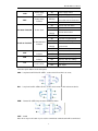
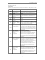
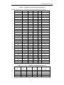
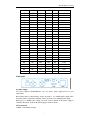
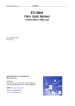
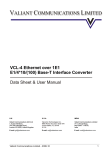
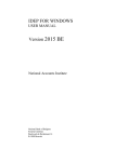
FE1-FE1*ETH Converter User Manual FE1-FE1*ETH User Manual 1 General Safety Information Please read the following safety rules to avoid any harm to human body and any damage to other devices when this device is connected to other devices. The product shall be used in specified applicable areas and shall be fixed by technical engineer authorized by us. To prevent fire and to avoid any harm to human body, please Use the appropriate power supply, check power supply type and differentiate anode and cathode carefully; Connect and cut-off properly: when device is powered, do not connect or cut off the data cable; Use proper grounding: before using the product, make sure the proper grounding is made , grounding impendence shall be less than 4ohm; Make the correct connection: ensure to use the default accessories provided along with the device. If you need to make the special connection, please note the PIN definition and make the proper connection; Avoid to touch exposed circuit When the circuit is on, do not touch exposed components if any; Do not operate the device without front panel; Provide good ventilation; Do not operate the device in the humid environment; Do not operate the device in the volatile environment; Keep the surface clean and dry. 2. Fast track FE1-FE1*ETH converter can combine and multiplex an Ethernet and an E1( user side) into an E1 channel and transmit through E1 channel. The bit rate of E1 and Ethernet can be adjusted provided the total bit rate does not exceed the E1 bit rate (1984Kbps). E1-M is uplink channel; E1-S is downlink channel. The PCB for standalone and rack version is same. Please indicate your requirement when order. The following are the operation steps: Connect with appropriate power supply as per back panel power indication; Power on, the device will do self-detection, PWR,E1LOS-M,E1LOS-S indicators shall be on, rest shall be off; Connect Rx of E1-M with Tx of E1 channel on transmission equipment, Tx to Rx ; E1LOS-M alarm indicator shall be off; if there is an error, you can press button to pinpoint the error; Based on client’s need, configure the time-slot of E1-S, connect E1 line to TX ,RX of E1-S, the E1LOS-S indicator shall be off; Based on Ethernet transmission requirement set up fixed timeslots (through 17~22th dipswitch), connect Ethernet cable, the LINK indicator shall be on, SPD,F/D indicator status shall be as per Ethernet working mode; If you operate as per above steps, the device still does not work, please contact your supplier or our technical staff for assistance. 3. Product Features 2 FE1-FE1*ETH User Manual Provide rich auto-operation and auto-calculation options. Users can configure the device easily; Self-learn Ethernet MAC address, decide forward or filter the data frame based on sourc MAC address and destination MAC address; Ethernet data rate can be configured based on E1-S data rate configuration; Local device can follow the configuration of remote device automatically or users can command remote device to follow local configuration; Provide rich alarming and loop testing function; 4. Technical Specifications E1 Interface Data rate: N*64Kbit/s (N=1-31) Coding: HDB3 Impedance: 75Ω(unbalanced)/120Ω(RJ48-C balanced) Standard: compliant with G.703、G.704 Jitter: compliant with G.832 Connector: Q9/RJ45 Alarm Indicators: code breaking, frame loss, CRC alarm, AIS Ethernet Interface data rate: N*64Kbit/s、N=1-31、 Transmission speed: 10/100M auto negotiation Duplex mode: full/hall duplex auto negotiation Power supply: Voltage: Stand-alone AC 220V/DC -48V optional Chassis-based: AC220V/DC-48V、hot redundancy and swappable; Voltage range: 180 VAC、260 VAC or -38 VDC 、 -72 VDC Power consumption: stand-alone: <5W Chassis-based: <75W Dimension: Stand-alone mini type: 218mm*136mm*44mm , 2 sets can be mounted on 1 19” rack Chassis-based: 483mm*165mm*177mm Operating environment: Working Temp.: -20、 、 +70、 Humidity: 95% 5. Front panel 5.1 Indicators There are 9 indicators on the front panel Indicator Name Function Status 3 Device Status FE1-FE1*ETH User Manual PWR TEST Power supply ON Power supply normal indicator OFF No power supply Testing status Blinking indicator E1 link alarm Normal ON E1 link code error alarm Intermittent blinking E1SYL-S~E1SYL-M LINK SPD F/D E1 data flow alarm indicator pressed at local or remote end OFF Blinking E1LOS-S~E1LOS-M One of the testing button is AIS alarm Remote device alarm OFF E1 link normal ON E1 frame not synchronized Blinking Intermittent blinking CRC-4 error checking Remote device frame not synchronized OFF E1 data receiving normal Ethernet Link ON Ethernet connected indicator OFF Ethernet not connected Ethernet data rate ON Ethernet data rate: 100Mbps indicator OFF Ethernet data rate: 10Mbps Ethernet Duplex ON Full duplex mode indicator OFF Half duplex 5.2 Push button There are 4 push buttons on the front panel; ANA: Loop from local E1-M to E1-S/ETH , used to check if local link is ok or not; DIG Loop from local E1-S/Eth to E1-M , used to check remote E1 link and remote device; REM Remote E1-S/ETH loop, the status of REM as follow: PATT Invalid Note: when any one of button is pressed, the normal data communication will be terminated, 4 FE1-FE1*ETH User Manual TEST indicator will be ON. 5.3 Dip Switch There are 3 group of dipswitch on the front panel, the definition of 1~24th position is as follow: S.No 1~5 6~8 Description Starting time slot of 0~31 time slots of E1-M see table 1; E1-M set by E1-S When all set OFF, means starting time slot is 0; Invalid reserved The 9~13 14 15 time-slot Detailed configuration see table 2; number of E1-M set When time-slot number is 0, means E1-S is not by E1-S used; Invalid reserved Framed mode enabled Close 16 Configuration When this position set to ON, framed mode is enabled E1LOS-S 、 E1SYL-S blinking alarm Ethernet When connected with remote E1 multiplexer, remote E1 device is not E1-S interface, E1LOS-S blinks. Set this position to ON to close this function; Time-slot number in E1-M Corresponding Ethernet time-slot number, from 0 to 31 ,in E1-M, see table 3; When time-slot number is 0, means Ethernet is not used; When the Ethernet 17~21 time-slot number is automatically configured, above setup is invalid; 22 Close automatic OFF-automatic configuration Ethernet time-slot ON- Close automatic configuration number When the device is in the automatic configuration configuration mode, based on the 15th dipswitch setup, the time-slot numbers in E1-M is what left by E1-S time slot numbers Command remote --Valid when set as ON; device to follow local --If this position is valid, all dipswitch except 6th and ‘s configuration 23rd dipswitch are invalid for remote device; --if this position of local and remote are both set as 23 ON, wrong configuration will be reported; --If 23rd,24th dipswitch of local device are set as ON, remote alarm message will not be sent to remote device; 24 Command local --valid when set as ON; device to follow --if this position is valid, all dipswitch except 6th remote’s and 24th dipswitch are invalid for local device; configuration ----If 23rd,24th dipswitch of local device are set as ON, remote alarm message will not be sent to remote device; 5 FE1-FE1*ETH User Manual Table 1: 1~5 dipswitch starting time-slot configuration rd **when starting time-slot is 3, E1-S will count time-slot number from 3 position; 5 4 3 2 1 Starting time-slot OFF OFF OFF OFF ON 1 OFF OFF OFF ON OFF 2 OFF OFF OFF ON ON 3 OFF OFF ON OFF OFF 4 OFF OFF ON OFF ON 5 OFF OFF ON ON OFF 6 OFF OFF ON ON ON 7 OFF ON OFF OFF OFF 8 OFF ON OFF OFF ON 9 OFF ON OFF ON OFF 10 OFF ON OFF ON ON 11 OFF ON ON OFF OFF 12 OFF ON ON OFF ON 13 OFF ON ON ON OFF 14 OFF ON ON ON ON 15 ON OFF OFF OFF OFF 16 ON OFF OFF OFF ON 17 ON OFF OFF ON OFF 18 ON OFF OFF ON ON 19 ON OFF ON OFF OFF 20 ON OFF ON OFF ON 21 ON OFF ON ON OFF 22 ON OFF ON ON ON 23 ON ON OFF OFF OFF 24 ON ON OFF OFF ON 25 ON ON OFF ON OFF 26 ON ON OFF ON ON 27 ON ON ON OFF OFF 28 ON ON ON OFF ON 29 ON ON ON ON OFF 30 ON ON ON ON ON 31 Table 2: 9~13 17~21 dipswitch configuration and data rate 13 12 11 10 9 Data rate 、21、 、20、 、19、 、18、 、17、 Kbit/s OFF OFF OFF OFF ON 64 OFF OFF OFF ON OFF 128 OFF OFF OFF ON ON 192 OFF OFF ON OFF OFF 256 6 FE1-FE1*ETH User Manual OFF OFF ON OFF ON 320 OFF OFF ON ON OFF 384 OFF OFF ON ON ON 448 OFF ON OFF OFF OFF 512 OFF ON OFF OFF ON 576 OFF ON OFF ON OFF 640 OFF ON OFF ON ON 704 OFF ON ON OFF OFF 768 OFF ON ON OFF ON 832 OFF ON ON ON OFF 896 OFF ON ON ON ON 960 ON OFF OFF OFF OFF 1024 ON OFF OFF OFF ON 1088 ON OFF OFF ON OFF 1152 ON OFF OFF ON ON 1216 ON OFF ON OFF OFF 1280 ON OFF ON OFF ON 1344 ON OFF ON ON OFF 1408 ON OFF ON ON ON 1472 ON ON OFF OFF OFF 1536 ON ON OFF OFF ON 1600 ON ON OFF ON OFF 1664 ON ON OFF ON ON 1728 ON ON ON OFF OFF 1792 ON ON ON OFF ON 1856 ON ON ON ON OFF 1920 ON ON ON ON ON 1984 6 Rear panel 6.1 power supply The device supports AC220V/DC-48V, you can choose power supply based on your requirement; When power switch is switched “48V”, means you want to use -48VDC power supply; when the power switch is switched to “220VAC”, means you want to use 220VAC power supply; When you use -48VDC power supply, you shall connect cathode of DC power supply to cathode of the device, anode of DC power supply to anode of device ; 6.2 E1 connector 75Ω/RX、 75Ω unbalanced input 7 FE1-FE1*ETH User Manual 75Ω/TX、 75Ω unbalanced E1 output; “M” mark means uplink E1 channel, “S” mark means downlink user side E1 channel; 6.3 Ethernet Interface (LAN interface) Ethernet interface supports cross-connection and cut-through auto-sensing; Note: when LAN cable is too long , please make sure to connect two PIN of RX into a same UTP, two PIN of TX into a same UTP; 6.4 Bottom panel ON、 means grounding of E1 link is connected with grounding of system; OFF、means grounding of E1 link is disconnected with grounding of system; The first position is RX grounding, the second position is TX grounding; Note : please make sure there shall be at least one side to be grounded. For example: if transmission equipment’s TX is grounded, our device is not necessary to be grounded; If transmission equipment is not grounded, our deviced shall be gournded; 7. Rack 7.1 Front panel Front panel There are 17 slots, 15 for NMS card and functional card, 2 for power supply card. NMS Card: If users need network management, the NMS card must be plugged into the first slot; if users do not need network management, this slot can be used for functional card; Function cards: Maximum 15 functional cars can be plugged. Various functional cars can be used. Power supply card: Users can plug the power supply module based on the requirement, the power can be 220VAC, -48VDC. 1+1 redundancy is supported. 7.2 Real panel 8 FE1-FE1*ETH User Manual 8. Typical application 1~5th dipswitch should be all OFF 6-8th dipswitch : reserved OFF 14 is invalide , it is resered 15th dipswith is also used to set PCM3 and PCM31 ON-PCM30 OFF-PCM31 16th dipswtich is used close the alarm of sub E1 is sub E1 is not connected to any E1 devices 22: OFF-automatical confirgure Etherent time slot ON-close automatic config 23: command remote device to follow local configuration, it's valid if ON 24: command local device to follow local config normanlly make if OFF , 23,24 CRC check is always enalbed; 9