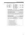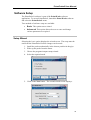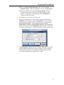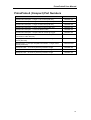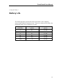
1
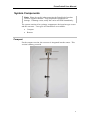
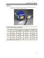
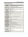
® ® ADS PrimeProbe 2 User Manual October 2009 QR 775016 A0 ADS LLC 4940 Research Drive Huntsville, Alabama 35805 Telephone: 1-800-430-3366 / Fax: 1-800-430-6633 www.adsenv.com PrimeProbe2 User Manual Copyright © 2009 ADS® LLC. All rights reserved. ADS® is a registered trademark of ADS LLC. PrimeProbe®, PrimeLog®, and PrimeWorks® are registered trademarks of Primayer Limited. All other brand and product names are trademarks or registered trademarks of their respective holders. Notice of Proprietary Information The information contained herein represents the latest information available at the time of publication. ADS reserves the right to make any changes or modifications to the content of this document, without notice, to reflect the latest changes to the equipment. No part of this document may be reproduced in any form without the written consent of ADS. ii PrimeProbe2 User Manual Table of Contents Chapter 1 Introduction ......................................................................1 System Components.....................................................................................2 Compact .................................................................................................2 Remote ...................................................................................................3 PrimeProbe2 Length Dimensions ..........................................................3 Technical Specifications ........................................................................4 Chapter 2 Installation ........................................................................5 Turning On the Unit.....................................................................................6 Compact Version (units acquired since June 2008) ..............................6 Compact Version (units acquired prior to June 2008)..........................6 Remote Version .....................................................................................6 Site Selection ...............................................................................................7 Installation and Operational Considerations................................................8 International Standard of Flow Measurement......................................10 Mechanical Considerations for Sensor Installation ...................................11 Plastic or AC Pipes (Fitting Gate Valve).............................................11 Steel Pipes (Fitting Gate Valve) ..........................................................11 Measuring the Internal Diameter of the Pipe.............................................12 Pipe Thickness Gauge..........................................................................12 Gauging Rod ........................................................................................12 Installing the PrimeProbe2.........................................................................14 Installation Procedure ..........................................................................15 Grounding the Sensor and the Converter.............................................15 Flow Direction .....................................................................................16 Connecting the Converter to the Sensor ....................................................17 Pulse Output Characteristics ................................................................18 Powering-up the PrimeProbe2 Sensor .................................................19 Menu Access System .................................................................................22 Factory Presets .....................................................................................22 QUICK START ...................................................................................23 Main Menu...........................................................................................23 Converter Functions...................................................................................31 Default Values .....................................................................................32 Entry Definitions................................................................................333 Chapter 3 Operation ........................................................................38 Software Setup ...........................................................................................39 iii PrimeProbe2 User Manual Setup Wizard........................................................................................39 Chapter 4 Part Numbers..................................................................41 PrimeProbe2 (Compact) Part Numbers .....................................................42 PrimeProbe2 (Remote) Part Numbers ........................................................43 Chapter 5 Battery Life......................................................................44 Chapter 6 Index… ............................................................................45 iv CHAPTER 1 Introduction The PrimeProbe®2 flow meter measures flow rate in closed pipes with clean water having a conductivity greater than 5 microsiemens. It is not suitable for measuring wastewater, gases, petroleum, or other fluids with low conductivity. 1 PrimeProbe2 User Manual System Components Note: Please be careful when removing the PrimeProbe2 product from its original container. Fully inspect the equipment for damage. If damage exists, notify the carrier and ADS immediately. The system consists of two primary components: the insertion-type sensor and the converter. Two types of PrimeProbe2 are available: Compact Remote Compact For the compact version, the converter is integrated into the sensor. This version is battery powered. 2 PrimeProbe2 User Manual Remote For the remote version, the converter connects to the sensor by a cable. This unit can be battery or externally powered. PrimeProbe2 Length Dimensions Model Insertion Length Overall Length Overall Length (Compact) (Remote) Use in Pipe Sizes* Size 1 11.8 inches (300 mm) 29.0 inches (737 mm) 30.2 inches (767 mm) ≤ 23.6 inches (600 mm) Size 2 19.7 inches (500 mm) 36.9 inches (937 mm) 38.1 inches (967 mm) ≤ 39.4 inches (1000 mm) Size 3 27.6 inches (700 mm) 44.8 inches (1137 mm) 45.9 inches (1167 mm) ≤ 55.1 inches (1400 mm) Size 4 39.4 inches (1000 mm) 56.6 inches (1437 mm) 57.8 inches (1467 mm) ≤ 78.7 inches (2000 mm) * Assumes operation on the centerline of the pipe 3 PrimeProbe2 User Manual Technical Specifications Parameter Specification Pipe Sizes 3.2 to 315.0 inches (80 mm to 8000 mm) – at 1/8 pipe diameter (insertion depth) installation Measurement Range Accuracy; Point Velocity Flow Repeatability Flow Determination Measurement Sampling Minimum Fluid Conductivity Process Connection Pipeline Pressure Rating Sensor Material Bi-directional from 0.03 to 16.40 feet per second (0.01 m/s to 5 m/s) (Maximum may be lower based on insertion length and pipe position.) ±0.0066 feet per second (± 2mm/sec) or ± 2%, whichever is the greater. Refer to ISO 7145-1982 ± 0.5% of velocity Assumes fully developed flow profile; ISO 7145-1982 reference Continuous or programmable from 1 to 90 seconds 5µS/cm 1-inch (25-mm) BSP (British Standard Pipe) 232 psi PTFE (polytetrafluoroethylene) Body Material SS304 Electrode Materials SS316 Flow Temperature 32º to 176º F (0 to 80º C) Safety Pressure Tapping Adjustment Method Protection Batteries Probe fitted with anti-bounce chain Female quick-release connector 5 mm Allen key (supplied by ADS) – fits all screws IP68 Type: Lithium batteries Life: ≤3 years (depending on sampling period and usage) Output: Signal Units Connection Pulses proportional to velocity/flow rate - maximum frequency 32 Hz User-selectable MIL-spec connector Communications USB 4 PrimeProbe2 User Manual CHAPTER 2 Installation This chapter provides instructions on powering up the PrimeProbe2, determining the appropriate length and position for the insertion sensor, selecting a suitable location for measurement, and installing the PrimeProbe2. 5 PrimeProbe2 User Manual Turning On the Unit ADS delivers the PrimeProbe2 in the OFF condition. The user must turn it on before going to the first installation site, as described in the following sections. Compact Version (units acquired since June 2008) 1. Launch the PrimeWorks® software. 2. Connect the PrimeProbe2 to the PC/laptop running the software using the communications cable. 3. Select the PrimeProbe2 > Shipping > Wake up menu option. The software will initiate communications with the PrimeProbe2 to bring it out of Sleep mode. The probe is now ready for use. Compact Version (units acquired prior to June 2008) 1. Using the 5mm Allen key (supplied by ADS), remove the 4 screws securing the rear cover of the converter. 2. Locate the two small switches left of center of the circuit board and in front of the battery. Place them in the LEFT position. 3. Replace the cover and the 4 screws, and then tighten the screws with the Allen key securely and evenly. Remote Version 1. Using the 5mm Allen key (supplied by ADS), remove the 4 screws securing the rear cover of the converter. 2. Locate the two small switches immediately behind the communications jack socket. Place these switches in the LEFT position. 3. Replace the cover and the 4 screws, and then tighten the screws with the Allen key securely and evenly. Note: Tighten all the screws fully to prevent water ingress from occurring. 6 PrimeProbe2 User Manual Site Selection The PrimeProbe2 can be used on pipes with internal diameters from 3.15 to 314.96 inches (80 to 8000mm) at 1/8 diameter insertion depth, based on the insertion length of the selected probe. The following table indicates the 4 different insertion lengths of the PrimeProbe2 and the pipe sizes in which they can operate. The PrimeProbe2 can be located at one of three depth positions: ½-pipe diameter, 1/8-pipe diameter, or 7/8-pipe diameter. Size of PrimeProbe2 Internal Diameters of Pipes at 1/8 Diameter Insertion Depth Size of PrimeProbe2 Internal Diameters of Pipes at 1/2 Diameter Insertion Depth 11.81 inches (300 mm) 3.15 to 78.74 inches (80 to 2000 mm) 11.81 inches (300 mm) 3.15 to 23.62 inches (80mm to 600mm) 19.69 inches (500 mm) 3.15 to 78.74 inches (80 to 2000 mm) 19.69 inches (500 mm) 3.15 to 39.37 inches (80 to 1000 mm) 27.56 inches (700 mm) 3.15 to 220.47 inches (80 to 5600 mm) 27.56 inches (700 mm) 3.15 to 55.12 inches (80 to 1400 mm) 39.37 inches (1000 mm) 3.15 to 314.96 inches (80 to 8000 mm) 39.37 inches (1000 mm) 3.15 to 78.74 inches (80 to 2000 mm) Before installing the PrimeProbe2, determine the direction of the flow in the pipe. The PrimeProbe2 must be installed in the correct direction. Using the symbols on the nameplate of the sensor (– to +) for reference, the PrimeProbe2 is installed correctly when the flow in the pipe travels from – to +. 7 PrimeProbe2 User Manual Installation and Operational Considerations Install the sensor away from any bends in the pipe and hydraulic fittings (disturbances). For the best results, install the sensor of the PrimeProbe2 at a location with at least 25 times the pipe diameter in distance of straight unrestricted pipe upstream of the sensor and 10 times the pipe diameter in distance of straight unrestricted pipe downstream of the sensor. Operate the PrimeProbe2 only in full pipes. The converter performs flow calculations based on full pipe. Before opening the valve to insert the PrimeProbe2, make sure the safety mechanism is engaged. Some pipes are under considerable pressure. Failure to lock-down the probe could allow pressure to force the sensor upward like a projectile, potentially causing injury to the installer. Although it is not always necessary to install the sensor at the 12 o’clock position on the pipe, it is always necessary to install the probe at a 90° angle to the length of the pipe. The PrimeProbe2, configured with a remote converter, can receive power from an AC mains supply. When using AC power, terminal connections with the mains supply should be made only by qualified technicians familiar with all current procedures and local codes. Connection to mains power should always occur through a RCD (residual current device) and should be the last step in the installation process. 8 PrimeProbe2 User Manual 9 PrimeProbe2 User Manual International Standard of Flow Measurement The following table has been reproduced, with permission, from ISO 7145 (BS 1042) Section 2.2 1982. Complete copies are available from BSI Publications, Linford Wood, Milton Keynes, MK14 6LE. Type of Disturbance Upstream from the CrossSection of Measurement Minimum Upstream Straight Length* For Measurement at the Point of Mean Axial Velocity For Measurement on the Axis of the Conduit 90-degree elbow or a t-bend 50 25 Several 90-degree coplanar bends 50 25 Several 90-degree noncoplanar bends 80 50 Total angle convergent 18 to 36 degrees 30 10 Total angle convergent 14 to 28 degrees 55 25 Fully-opened butterfly valve 45 25 Fully-opened plug valve 30 15 * Expressed in multiples of the diameter of the conduit. 10 PrimeProbe2 User Manual Mechanical Considerations for Sensor Installation Install the probe into the pipe through a pre-drilled 1-inch (25-mm) hole in the pipe using a 1-inch (25-mm) Ball Valve (included). A 1.5-inch or 2inch ball valve may be used with reducers. Installing in plastic or AC (asbestos cement) pipes with smaller diameters and steel pipes with larger diameters requires different methods. Plastic or AC Pipes (Fitting Gate Valve) Plastic or AC pipes require a gate valve; however, no welding is required to install the gate valve onto a 7.87- to 15.75-inch (200- to 400-mm) diameter plastic or AC pipe. Simply mount a saddle to the existing pipe, tighten the lug nuts, and connect the 1.57-inch (40-mm) gate valve. Note that a 1.57-inch (40-mm) drill bit must be used when boring a hole in the pipe. Do not install reducers if they will interfere with a protruding drill bit. Steel Pipes (Fitting Gate Valve) To connect a gate valve to a large-diameter steel pipe, first weld a carbon steel boss directly to the pipe. After welding the boss to the pipe and pressure-testing the weld, attach a 1.57-inch (40-mm) gate valve. Note: A carbon steel boss cannot be welded effectively to a ductile iron pipe. When using the PrimeProbe2 with ductile iron pipes, use a pipe saddle. 11 PrimeProbe2 User Manual Measuring the Internal Diameter of the Pipe After successfully attaching the 1-inch (25-mm) boss to the pipe, it is critical to take an accurate measurement of the internal diameter of the pipe (pipe ID). This can be done using one of the following: Pipe thickness gauge Tape measure Gauging rod Pipe Thickness Gauge Use an Ultrasonic Pipe Thickness Gauge to measure the ID of the pipe in the following way: 1. Measure the circumference of the pipe using a measuring tape. 2. Divide the measured circumference by ð (pi) to obtain the outside diameter of the pipe. 3. Use the ultrasonic pipe thickness gauge to measure the thickness of the pipe wall. 4. Multiply the pipe thickness by 2 and subtract the result from the outside diameter. Gauging Rod Use a gauging rod to measure the pipe ID in the following way: 1. With the valve closed, connect the gauging rod to the ball valve. Make sure the measuring arm is aligned correctly with the pipe (see step 1 in the following figure). 2. Open the valve completely, and lower the gauging rod until it touches the bottom of the pipe. With the gauging rod touching the bottom of the pipe, rotate the gauging rod 180 degrees and then lock-down the upper measuring-lip (see step 2). 3. Withdraw the gauging rod until it touches the top of the pipe wall. With the gauging rod touching the top of the pipe wall, lock-down the lower measuring lip. The distance between the two knife-edges of the measuring lips is the internal diameter of the pipe (see step 3). 4. Rotate the gauging rod 180-degrees, and withdraw the gauging rod the rest of the distance (i.e., clearing the valve). Close the ball valve completely. Remove the gauging rod (see step 4). 12 PrimeProbe2 User Manual 13 PrimeProbe2 User Manual Installing the PrimeProbe2 Once the boss/valve is installed, insert the PrimeProbe2 into the pipe. To do this, first determine whether to install the PrimeProbe2 on the centerline of the pipe (1/2-pipe) or at the mean velocity point (1/8 or 7/8-pipe). Centerline installation is the preferred method because it allows for a greater margin of error if installation does not occur exactly on the centerline. Choose the 1/8- or 7/8-pipe (mean velocity) method only when the PrimeProbe2 is not long enough to reach the centerline or the flow velocity is excessive. Use caution when using 7/8 insertion on larger diameter pipes because excessive velocity can bend the instrument. 14 PrimeProbe2 User Manual Installation Procedure 1. Determine the appropriate Z-value for the selected insertion depth, and then secure the reference ring at that value. Available Insertion Depths Insertion “Z-value” 1/8D L - (X + S + 1/8D + 110) 1/2D L - (X + S + 1/2D + 110) 7/8D L - (X + S + 7/8D + 110) S = pipe thickness D = internal diameter of pipe X = distance between (outside) top of pipe and top edge of ball valve Z = distance between top edge of reference ring and bottom edge of converter box L = see following table Insertion Length L 11.81 inches (300 mm) 25.59 inches (650 mm) 19.69 inches (500 mm) 33.46 inches (850 mm) 27.56 inches (700 mm) 41.34 inches (1050 mm) 39.37 inches (1000 mm) 53.15 inches (1350 mm) Caution: Before continuing, make sure the anti-bounce chain is attached and secure. 2. With PrimeProbe2 fully retracted, screw the 1-inch sensor sleeve into the pipe. 3. Make sure the chain is at full extent. 4. Slowly open the ball valve. Make sure the valve is 100% open. 5. Slowly push the sensor through the open valve into the pipe until the reference ring touches the locking collar. 6. Verify that the push handles of the PrimeProbe2 are in alignment with the pipe axis (±2 degrees). 7. Tighten the two side screws. Grounding the Sensor and the Converter For accurate results, both the sensor and the flow must be at the same potential. To achieve this, always connect both the sensor and the transmitter to ground. Contact ADS concerning pipes with cathodic protection. 15 PrimeProbe2 User Manual Note: Fluctuating flow rates usually are an indication of poor grounding. Flow Direction Prior to completing installation, confirm the direction of the flow in the pipe. Using the nameplate as a reference, flow direction is positive when the flow travels from – to +. If the flow occurs in reverse following installation, reverse the probe by rotating it 180 degrees. Another option is to reverse the sign of the KA Factor (refer to the Programming the Converter); however, ADS does not recommend this option. 16 PrimeProbe2 User Manual Connecting the Converter to the Sensor Note: Only the remote version requires the user to connect the sensor to the converter; the compact version is connected internally at the factory. ADS delivers the remote PrimeProbe2 with the sensor cables terminated and potted at the sensor-end. Therefore, no further user intervention at the sensor terminal box should be necessary. However, ADS has intentionally left the converter-end of the cables loose, allowing the user to cut the sensor cables length to accommodate the application. ADS does not recommend extending the cables because each cable has a separate screen. Connect the converter to the sensor in the following way: 1. Loosen the two lowest cable glands on the side of the converter. Warning: Be sure that power is not connected to the converter. 2. Remove the back panel from the converter. 17 PrimeProbe2 User Manual 3. Insert the two sensor cables through the cable glands into the termination area of the converter. 4. With the back removed and the terminals exposed, terminate the appropriate wires at the numbered terminals. 5. To use the pulse output of the PrimeProbe2, connect the appropriate digital output cable to terminals 16 & 17 (output 1) and 18 & 19 (output 2). Pulse Output Characteristics The pulse output has the following technical characteristics: Opto-insulated output with floating collector and emitter terminals, freely connectable Maximum switching voltage: 40Vdc 18 PrimeProbe2 User Manual Maximum switching current: 10mA Maximum switching frequency: 32Hz Insulation from other secondary circuits: 500 Vdc Powering-up the PrimeProbe2 Sensor The PrimeProbe2 Remote can receive power from either lithium (nonrechargeable) batteries or mains power. Battery To avoid rapid depletion of the battery(s), the sampling rate is preset to 5 seconds (refer to the E. saving setting description in the Measure submenu section beginning on page 26). The user can adjust this rate, but this may sacrifice battery life. Refer to the battery life specification (Chapter 5, Battery Life, on page 44) to determine the expected battery life for different sampling regimens. ADS supplies 4 lithium batteries: a single pack and a 3-pack of batteries. Mains When using mains power, the PrimeProbe2 operates in continuous sampling mode. The user may leave one lithium battery (single-pack) installed under mains power to serve as a backup battery in the event of a mains failure. If the mains power becomes unavailable, the unit will automatically switch over to the backup battery as the power source. Connecting the Battery Packs In battery mode, the user can connect either 1 lithium battery or 4 lithium batteries. One battery can serve as either the sole power source or the backup power supply to a mains-powered unit. Using 4 batteries can provide up to a 10-year battery life. Refer to the Battery Life table in Chapter 5, Battery Life, on page 44. To activate the batteries as the main power source, first activate the applicable dip switch. In the Off mode, the PrimeProbe2 will not use the battery pack connected to that terminal. In the ON mode, the PrimeProbe2 will use the battery pack as the main source of power. With the batteries connected (and no mains power), turning the dip switch to ON will power-up the converter (similar to an On/Off switch). 19 PrimeProbe2 User Manual Note: With the battery packs connected and the dip switches ON, the PrimeProbe2 is now functional. The next step is to configure the converter corresponding to the specific application. Connecting Mains Power Important Precautions to Consider Before Connecting to Mains Power Only qualified technicians with appropriate knowledge of local codes and practices should make connections to mains power. Verify the mains voltage falls within the limits stated on the tag plate. Use appropriate fireproof wire and connectors in accordance with local code. Equip mains power supply line with external protection for current overload (i.e., fuse or automatic line breaker with limiting capacity of less than or equal to 3A @ 240V). Circuit breaker should be located within close proximity to the PrimeProbe converter. 1. Shut off the mains power supply at the closest circuit breaker. 2. Remove the back from the PrimeProbe Converter. 3. Loosen the topmost gland on the side of the converter. 4. Slide the mains cable through the gland and into the termination area of the converter. 20 PrimeProbe2 User Manual 5. Connect the mains cable to the M3 terminal in the termination area of the converter. 6. Allow a little bit of slack for all cables (i.e., sensor, power, and digital) and tighten all the cable glands on the outside of the PrimeProbe2 converter. Tighten the glands by hand, and then give them an extra ½-turn using a crescent wrench. 7. Replace the back cover onto the PrimeProbe2 converter. After successful installing the sensor and connecting the converter to the PrimeProbe2 sensor, configure the converter. Program a PrimeProbe2 with an integrated converter using the PrimeWorks software on a PC/laptop. A PrimeProbe2 with a remote converter can be programmed using either the PrimeWorks software or the 3-key membrane keypad on the front of the converter. Instructions on programming the PrimeProbe2 using PrimeWorks are at the end of this section. 21 PrimeProbe2 User Manual Menu Access System This section applies only to the remote PrimeProbe2. Navigate through the menu system using the keypad. The following table describes the 6 key functions: Short Press <1 Second Increases the numeric value or parameter selected by the cursor Goes to the previous item in the menu Long Press >1 Second Decreases the numeric value or parameter selected by the cursor Goes to the next item in the menu Short Press <1 Second Moves the cursor to the right in an input field Goes to the next item in the menu Changes the display of the process data Long Press >1 Second Moves the cursor to the left in an input field Goes to the previous item in the menu Short press <1 Second Enters/edits the selected function Enables the Main Menu for system configuration Cancels the selected function in progress Long Press >1 Second Exits the current menu Confirms/enables the selected function Enables Totalizer Reset Request Factory Presets The PrimeProbe2 comes from the factory with the following configuration: Dip switches in the OFF position Access Code L2 = 00000 (ADS recommends leaving for PrimeWorks programming) 22 PrimeProbe2 User Manual With the access code set at 00000, the user has access to all levels of the Menu Access System without needing a password. The parameters available depend on the dip switches inside the converter. When first powered ON, the display will show the Quick Start Screen. Press the key on the keypad. Scroll through the Quick Start Options until reaching the Main Menu. The sequence occurs as follows: QUICK START Full Scale Total Multiplier Units Pulse-1 Pulse-2 Tpls-1 (time of pulse) Tpls-2 Language Main Menu The Main Menu contains the following 11 sub-menus: 1. Sensor 2. Scales 3. Measure 4. Alarms 5. Inputs 6. Outputs 7. Communication 8. Display 9. Data logger 10. Diagnostic 11. Internal Data Many of the sub-menus have been preset at the factory and, therefore, require no user input. Sensor ND = mm Represents the internal pipe bore diameter of the pipe in which the PrimeProbe2 will be inserted. Using the keypad, insert the pipe ID at this position. 23 PrimeProbe2 User Manual KA = Represents the calibration data of the sensor. This is set at the factory and also is available on the nameplate. Changing this parameter will invalidate the calibration. S. model = Represents the sensor model and is set at the factory. Verify that the numbers here are the same as the first two characters of the serial number on the sensor. Do not change these numbers. Ins. Position Represents the depth at which the PrimeProbe2 will be inserted. Use the following numbers to indicate the insertion position: 0 for 1/8-pipe insertion depth 1 for ½-pipe insertion depth 2 for 7/8-pipe insertion depth The probe stores values of F1 and Fp. KL+ and KL- Represent factory parameters and require no user intervention. E.P. Detection Represents the function that enables/disables the Empty Pipe Detection feature. The setting toggles between On and OFF. If it is set to ON when the converter detects the pipe is empty, the following occurs: EMPTY PIPE displays on the screen. The flow rate indicator drops to zero. The totalizers stop advancing. An alarm is sent to either OUT1 or OUT2, as configured. E.P. Calibration Enables the automatic calibration procedure for the Empty Pipe Detection feature. Please note that the E.P. Detection function should remain OFF until this calibration is performed. Autozero Cal. Initiates the automatic zero calibration function. Please note that this function must be performed at startup or when the pipe has been empty for a long period of time. To perform this function, the pipe must be completely full and exhibit no movement of flow. Even small movements in the flow can cause inaccuracies. Perform the following to proceed with this function: With the cursor on Autozero Cal., press the up-arrow for more than one second and then release. Verify that the flow rate drops to (and stabilizes at) zero. If it does, then repeat this procedure. If the flow rate does not stabilize at/around zero, clean the probe tip. If a problem still occurs, check for cable damage and make sure both the sensor and the converter are properly grounded. 24 PrimeProbe2 User Manual Scales Unlike many conventional measurement instruments, the PrimeProbe2 has two ranges (N.1 and N.2). Fs2 is more likely to be used with 4-20mA outputs, but one of the outputs must be configured to indicate a change in range. The Scales menu includes the following parameters: Fs1 Represents the Full Scale value for Range N.1 Fs2 Represents the Full Scale value for Range N.2 For normal operation, select Fs1 to be a value (depending on the pipe size entered) equivalent to a flow velocity of 16 feet per second (5 m/s). Note: It is very important to select the appropriate values for Fs1 and Fs2. These numbers will be the basis for future parameters (e.g., both Flow Cutoffs and Thresholds are described as a percentage of Full Scale) Tot. MU Represents the units of measure as well as the number of decimal places in the totalizers. Change these parameters in the same way used to change any other parameter. Position the cursor over the appropriate parameter, press Enter, and then use the uparrow to change the values. Imp1 Represents the pulse value of channel-1, the volume of each pulse. Complete three fields for IMP1: Unit of Measurement Type of Unit Numeric Value Use the right-arrow to position the cursor between the units of measurement and the numerical value and then use the up-arrow to change the units of measure. Pressing the right-arrow for 1 second will confirm the changes to the units of measure. Next, use the right-arrow to move to the numerical values, and use the up-arrow to scroll through each location 0-9. Pressing the up-arrow for more than a second will confirm the numerical selection and move the cursor to the right. Imp2 Represents the pulse value for channel-2. Configure it in the same manner as Imp2. For ADS data loggers, keep this value the same as IMP1. Tpul1 Represents the duration of the pulse generated on Channel1. This parameter is measured in milliseconds (ms) and must be between 16 and 9999.99 ms. Use the up-arrow and the right-arrow to set these values. The value should be 16 ms for a PrimeLog®. Note: The user must determine whether the duration of the pulse is compatible with the external device to which it is connected. 25 PrimeProbe2 User Manual Tpul2 Represents the duration of the pulse generated on Channel2. Set up the same way as Tpul1. Note: Setting the Imp1/Imp2 and Tpul1/Tpul2 incorrectly may result in sending erroneous signals to the external device. Measure Tconst=s Effects the response time between the measured value and the displayed/output value. Cut-off = % Represents the low-flow threshold. Its nominal value is a percentage of Full Scale (set for Fs1 in the Scales submenu ). When the flow rate drops below this value, the flow is assumed to be zero and totalizers and output respond accordingly. This value can be set from 0 to 25% (of full scale). AutoCal = Represents the auto calibration feature and toggles between On and OFF. When enabled, the PrimeProbe2 performs an auto-calibration cycle once every hour. The procedure lasts from 9 to 15 seconds. During this period, the flow rate is frozen, but not lost. This means that during the autocal process, the PrimeProbe2 registers the same flow rate as the last reading taken before the autocal process began. Use auto calibration to remove temperature-induced errors and at locations that experience large temperature variations. Autorange= Allows the PrimeProbe2 to switch automatically from the Fs1 to Fs2 range (N.1 to N.2). This function is useful for pipes with large variations in flow rate. Fs2 must be set at a greater value than Fs1. Toggle this feature On and Off. Any external device connected to the PrimeProbe2 must acknowledge changes in range. E. saving Represents an energy saving feature and works in conjunction with the time constant. The default setting is ON. This allows for 5-second sampling intervals. If turned off, the probe will sample at 20Hz, which may cause rapid battery depletion. Use only when connected to a mains power source. Alarms Typically, PrimeProbe2 users will connect the instrument to an ADS data logger, using both outputs (one for forward flow; one for reverse flow). Under this configuration, the data logger (not the PrimeProbe) will manage the threshold alarms. If the user chooses not to use the PrimeProbe2’s alarm capabilities, the user must allocate one of the outputs (typically, OUT2) for this task. The Alarm menu contains the following: 26 PrimeProbe2 User Manual Max Thr+=% Represents the alarm setting for maximum forward flow. When the flow rate exceeds this setting, an alarm event will be generated. Enter the value of this alarm as a percentage of Fs1, from 0 to 125%. To disable the alarm, set the percentage to zero. Max thr-=% Represents the alarm setting for the maximum reverse flow. Setup this parameter similar to Max Thr+=%. Min thr+=% Represents the alarm setting for the minimum threshold value for forward flow. When the flow rate drops below this value, an alarm will be generated. Set this parameter at a value between 0 to 125% of Fs1. Min thr-=% Represents the alarm setting for the minimum threshold of reverse flow. Configure this parameter in the same way as Min thr+=%. Hyst.=% Represents the Hysteresis threshold, or dead-zone, for the Max/Min thresholds. Enter this threshold as a percentage of Fs1. For example, when the Hysteresis threshold is set at 10, the flow rate must drop above/below the Min/Max thresholds by more than 10% before generating an alarm. All ADS data loggers (included in the Water Loss Control Products family) have the same feature. E.p. thr.= Represents the empty pipe threshold and is set automatically by the E.P. Calibr. parameter in the Sensor submenu. Inputs Currently, the PrimeProbe2 does not include ports for inputs. However, this device may support this capability sometime in the future. Outputs The PrimeProbe2 comes preconfigured to provide both forward and reverse pulses through an ADS digital cable. Therefore, modifying the Outputs parameters in should not be necessary unless the application requires connection to a different device. However, following is a brief description of the menu options: Out1 = Represents the menu for setting the output functions of Output-1. The following table lists the available functions: OFF Disabled #1 IMP+ Pulse on N.1 for forward flow #1 IMP - Pulse on N1 for reverse flow #1 IMP +/- Pulse on N.1 for Net flow #2 IMP + Pulse on N.2 for forward flow #2 IMP - Pulse on N.2 for reverse flow 27 PrimeProbe2 User Manual #2 IMP +/- Pulse on N.2 for net flow Sign Flow direction output Range Range Indication output Max. Al+ Flow exceeds Maximum Threshold+ Max Al- Flow exceeds Minimum Threshold - Max +/- Flow exceeds Net threshold Min Al+ Flow below Minimum Threshold + Min Al - Flow below Minimum threshold - Min Al +/- Flow below net threshold P. pipe Empty Pipe alarm Out2 = Is set to the output functions of Out2 and is configured using the same procedures as Out1. Communications Besides the integrated keypad of the PrimeProbe2 with remote display, only one other communication protocol exists. This protocol, IF2, uses a PrimeProbe-PC link cable (USB) for configuration. The user can also configure the PrimeProbe2 using the PrimeWorks software with this protocol. Set this parameter to HTP for PrimeWorks communication. Display Language Allows the user to select from among several languages for the PrimeProbe2 display: E = English I = Italian F = French S = Spanish T+ reset Allows the user to reset the Forward Totalizer using the keypad. Simply press Enter, and the Execute? message will appear. HOLD Enter again, and a Done message will display. P+ reset Allows the user to reset the Partial fFrward totalizer. Use the same procedure as described in T+ reset. T- reset Allows the user to reset the Reverse Totalizer. Use the same procedure as described in T+ reset. P- reset Allows the user to reset the Partial Reverse Totalizer. Use the same procedure as described in T+ reset. D. Times Allows the user to set the amount of time, since the keypad was last used, before the display turns itself OFF. Enter this value in seconds. To turn the display back ON, simply hold 28 PrimeProbe2 User Manual down any key on the keypad for more than 1 second. After releasing the key, characters will appear on the display. Note: When the display is on, energy save mode goes off, reducing battery life significantly. Please keep in mind that even though the display may be OFF, the PrimeProbe is still in operation and measuring flow. If the PrimeProbe2 will not be used for an extended period of time, place the instrument in standby mode (described in Stand-by under Diagnostics). Quick Start = Allows the user to toggle On or Off the Quick Start Menu. Net Total = Allows the user to turn On or Off the display of Net Totals. Currency = Activates the currency functions. When activated, a currency value appears on the display in place of the totalizers (i.e., a monetary value appears that is equivalent to the totals). This corresponds to the Partial Totalizers. When the partial totalizers are reset, the currency totalizers are also reset. Curr. Decim. = Allows the user to select the number of decimal places in the Currency display. Choose from 0 to 3. Data Logger PrimeProbe2 does not have an internal data logger. Program the external data logger separately from the PrimeProbe2 using PrimeWorks software. This menu exists for possible future functionality. Diagnostics Calibration Allows the user to calibrate the sensor. Press the Enter key with the cursor on Calibration. Execute? will appear on the display. Press Enter to confirm, or any other key to cancel the operation. Self Test Allows the user to test all the functions of the PrimeProbe2, including all the input circuits and the excitation generator. Initiate the test by pressing the Enter key. When Execute? appears on the display, press Enter to confirm. After completion, the results from the test will appear on the display. This test occurs every time the user turns on (powers up) the unit. Simulation Facilitates flow rate simulation. This function is useful when testing external units connected to the PrimeProbe2. Toggle On/Off to start/stop this feature. Stand-by Allows the user to place the PrimeProbe2 in standby mode when it will not be used for an extended period of time. To activate this function, press the Enter key. When the Execute? 29 PrimeProbe2 User Manual message displays, press Enter again. The instrument will switch over to standby mode. To re-activate the PrimeProbe2, hold down any one of the three keys on the keyboard for more than 1 second. In standby mode, the PrimeProbe2 consumes about 50 mA of power. Internal Data L2 keycode Allows the user to set a Level-2 access code. This code may range from 00001 to 65535. Block Level Allows the user to set a level from 0 to 3. Each level enables and disables certain functions. Load fact. Pres. Allows the user to reset the factory default settings, eliminating previous settings entered by the user. Load user pres. Allows the user to save the current settings as user pre-settings in the Save user pres. fields. Hours Represents the total amount of time the PrimeProbe2 has been in operation. The user cannot edit this field. KS = Represents a sensor calibration factor and should not be changed under any circumstances. 30 PrimeProbe2 User Manual Converter Functions This section shows the functions and descriptions of the PrimeProbe2 settings. The entries in blue represent advanced entries (used in the PrimeWorks software). 31 PrimeProbe2 User Manual Default Values This section details the default values. Sensor ND = 200 mm (7.87 inches) Ins Position = 0 Scales FS1 = m3/h 342 32 PrimeProbe2 User Manual Tot. MU = m3 1.0000 Imp1 = m3 0.01 (i.e., 10 l/sec) Imp2 = m3 0.01 (i.e., 10 l/sec) Tpul1 = s 0.016 Tpul2 = s 0.016 Measure Tconst=s 45 Step through = 50% Outputs Out1 = Imp1+ Out2 = Imp2Communication IF2 = HTP Display Quick Start = On Net Total = On Entry Definitions 33 PrimeProbe2 User Manual 34 PrimeProbe2 User Manual Available units of mass and volume 35 PrimeProbe2 User Manual 36 PrimeProbe2 User Manual 37 PrimeProbe2 User Manual CHAPTER 3 Operation This section includes instructions on setting up the PrimeProbe2 using the PrimeWorks software. 38 PrimeProbe2 User Manual Software Setup The PrimeProbe2 software is part of the PrimeWorks software application. To access PrimeProbe2, launch the PrimeWorks software and select the PrimeProbe2 menu. Two methods of software setup are available: Basic This option runs a wizard. Advanced This option allows the user to enter and change various parameters as required. Setup Wizard Selecting the basic option displays the wizard screen. The setup must be read from the PrimeProbe2 before changes can be made. 1. Install the probe mechanically in the chosen position in the pipe. 2. Wake up the probe from the menu. 3. Choose the program/compact setup wizard. 4. Select the required mode. 5. Click on the Next button. The second wizard screen displays: 39 PrimeProbe2 User Manual Enter the Internal Pipe Diameter and select the Sensor Insertion Point. ADS recommends centerline (Centre Line). ADS recommends selecting the Energy Saving checkbox. Leaving it unselected will cause the rapid depletion of the battery. This option is available only when Permanent is selected on the first screen. 6. Click Next to go to the last wizard screen. 7. Enter the maximum flow value either by selecting a flow rate (Manual) or specifying a velocity (Automatic). This scales the output pulses deriving an FCAL value that will be programmed into the attached logger. The maximum output from the PrimeProbe2 is 32Hz. If the maximum flow for a site is unknown, ADS recommends selecting Automatic and setting the velocity to 7 feet per second (2 m/s). Velocity is unlikely to exceed this value. 8. Click Program to display the FCAL value. This is the value that will be programmed into the connected logger. When using an ADS PrimeLog, make sure the logger is programmed with the sensor type PrimeProbe2 and this FCAL value. 40 PrimeProbe2 User Manual CHAPTER 4 Part Numbers This chapter includes the part numbers for the compact and remote versions of the PrimeProbe2. 41 PrimeProbe2 User Manual PrimeProbe2 (Compact) Part Numbers Part PrimeProbe2 Compact – Length: 11.81 inches (300 mm) PrimeProbe2 Compact – Length: 19.69 inches (500 mm) PrimeProbe2 Compact – Length: 27.56 inches (700 mm) PrimeProbe2 Compact – Length: 39.37 inches (1000 mm) PrimeProbe2 Compact – Communications Cable PrimeProbe2 Compact – Output Cable to PrimeLog Logger PrimeProbe2 Compact – Output Cable to Bare Wires (for connection to other devices) ADS Part Number RXG810-001 RXG811-001 RXG812-001 RXG813-001 RXG820-001 RXG921-001 RXG826-001 Gauging Rod – 1-inch (25 mm) BSP Connection – Length: 19.69 inches (500 mm) TXG101/3-001 Gauging Rod – 1-inch (25 mm) BSP Connection – Length: 39.37 inches (1000 mm) TXG101/6-001 Transport Case – 11.81-inch (300-mm) Insertion Length Transport Case – 19.69-inch (500-mm) Insertion Length Transport Case – 27.56-inch (700-mm) Insertion Length RXG822-001 RXG823-001 RXG827-001 42 PrimeProbe2 User Manual PrimeProbe2 (Remote) Part Numbers Part ADS Part Number PrimeProbe2 Remote (Sensor + Converter) – Length: 11.81 inches (300 mm); Cable Length:16 feet (5 m) RXG814-001 PrimeProbe2 Remote (Sensor + Converter) – Length: 19.69 inches (500 mm); Cable Length: 16 feet (5 m) RXG815-001 PrimeProbe2 Remote (Sensor + Converter) – Length: 27.56 inches (700 mm); Cable Length: 16 feet (5 m) RXG816-001 PrimeProbe2 Remote (Sensor + Converter) – Length: 39.37 inches (1000 mm); Cable Length: 16 feet (5 m) RXG817-001 PrimeProbe2 Remote – Communications Cable RXG821-001 PrimeProbe2 Remote – Output Cable to PrimeLog Logger RXG925-001 Gauging Rod – 1-inch (25 mm) BSP Connection – Length: 19.69 inches (500 mm) TXG101/3-001 Gauging Rod – 1-inch (25 mm) BSP Connection – Length: 39.37 inches (1000 mm) TXG101/6-001 43 PrimeProbe2 User Manual CHAPTER 5 Battery Life The following table provides the battery life based on the sampling interval and number of batteries in use. However, whatever the results, the maximum battery life is limited to 10 years. Sampling Time (seconds) Battery Life – 1 Battery (years) Battery Life ‘N’ batteries (years) 1 0.7 0.7 * N 2 1.3 1.3 * N 5 2.1 2.1 * N 10 2.7 2.7 * N 15 3.0 3.0 * N >=30 5 5.0 * N 44 PrimeProbe2 User Manual CHAPTER 6 Index Application, 1 Battery, 19 Battery Life, 44 Communication Default Values, 33 Compact, 2 Connecting Mains Power, 20 Connecting the Converter to the Sensor, 17 Converter Functions, 31 Default Values, 32 Display Default Values, 33 Flow Direction, 16 Gauging Rod, 12 Grounding the Sensor and the Converter, 15 Important Precautions Before Connecting to Mains Power, 20 Installation, 5, 14 Installation Considerations, 8 Installation Procedure, 15 International Standard of Flow Measurement, 10 Introduction, 1 Mains, 19 MAS, 22 Measure Default Values, 33 Measuring the Internal Diameter of the Pipe, 12 Mechanical Considerations, 11 Menu Access System, 22 Operation, 38 Operational Considerations, 8 Outputs Default Values, 33 Part Numbers, 41 Pipe Thickness Gauge, 12 Plastic or AC pipes, 11 Powering-up the PrimeProbe2 Sensor, 19 PrimeProbe2 Length Dimensions, 3 Pulse Output Characteristics, 18 Remote, 3 Scales Default Values, 32 Selecting a Site, 7 Sensor Default Values, 32 Software Setup, 39 Specifications, 4 Steel Pipes, 11 System Components, 2 Turning On the Unit, 6 45