1
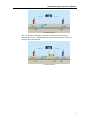
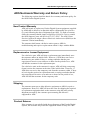
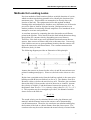
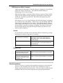
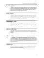
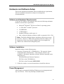
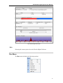
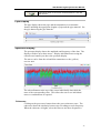
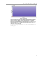
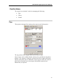
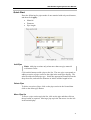
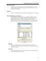
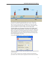
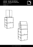
ADS® Eureka Digital System User Manual October 2009 QR 775020 A0 ADS LLC 4940 Research Drive Huntsville, AL 35805 Telephone (256) 430-3366 / Fax (256) 430-6633 www.adsenv.com ADS Eureka Digital System User Manual Copyright © 2009 ADS® LLC. All rights reserved. ADS® is a registered trademark of ADS LLC. Microsoft®, Windows®, and Internet Explorer® are registered trademarks of Microsoft Corporation. Intel® and Centrino® are registered trademarks of Intel Corporation. All other brand and product names are trademarks or registered trademarks of their respective holders. Notice of Proprietary Information The information contained herein represents the latest information available at the time of publication. ADS reserves the right to make any changes or modifications to the content of this document, without notice, to reflect the latest changes to the equipment. No part of this document may be reproduced in any form without the written consent of ADS. ii ADS Eureka Digital System User Manual Table of Contents Chapter 1 Introduction ...................................................................... 1 System Features ...........................................................................................3 Transmitters ...........................................................................................3 Automatic Velocity Measurement .........................................................3 In-Case Battery Charging ......................................................................3 Advanced Analysis Software.................................................................3 System Components and Options ..........................................................4 Optional Equipment and Software.........................................................4 ADS No-Hassle Warranty and Return Policy..............................................5 New Product Warranty ..........................................................................5 Replacement or Loaner Equipment .......................................................5 Shipping .................................................................................................5 Product Returns......................................................................................5 Chapter 2 Principles of Leak Noise Correlation.............................. 7 Methods for Locating Leaks ........................................................................8 Sensor Position...........................................................................................10 Leak Beyond the Sensors.....................................................................10 Leak on Connecting Pipe .....................................................................10 Chapter 3 System Components...................................................... 11 Descriptions ...............................................................................................12 Transmitter...........................................................................................12 Accelerometers ....................................................................................14 Receiver Unit .......................................................................................15 Headphones..........................................................................................15 Magnetic Antenna................................................................................15 Car Charge Cable.................................................................................16 Mains Charger......................................................................................16 Transmitter Y-Cable ............................................................................16 Receiver USB Cable ............................................................................16 Transport Case .....................................................................................16 Software CD.........................................................................................16 Small Tablet Computer (optional) .......................................................17 Ruggedized Tablet Computer (optional) .............................................17 Chapter 4 Getting Started ............................................................... 19 Hardware and Software Setup ...................................................................20 Software and Hardware Requirements ................................................20 Software Installation ............................................................................20 Power Management .............................................................................20 iii ADS Eureka Digital System User Manual Chapter 5 Eureka Digital Software ................................................. 21 Splash Screen .............................................................................................22 Main Screen ...............................................................................................23 Main Menu.................................................................................................24 File Menu .............................................................................................24 Run Menu.............................................................................................27 View Menu...........................................................................................28 Delayed Recording Menu ....................................................................30 Correlation Mode Menu.......................................................................33 Help Menu ...........................................................................................33 Toolbar Buttons .........................................................................................34 Display Area ..............................................................................................35 Correlation Display..............................................................................35 Zoom/Peak Noise Suppression ............................................................35 Buttons .................................................................................................36 Pipe Display .........................................................................................37 Spectrum Display.................................................................................37 Tracker .................................................................................................38 Control Area...............................................................................................40 Pipe ......................................................................................................40 Quick Start ...........................................................................................41 Filters ...................................................................................................46 Sound ...................................................................................................48 Chapter 6 Deployment..................................................................... 50 Choosing the Transducer Type ..................................................................51 Attaching the Transducers .........................................................................52 Accelerometers ....................................................................................52 Hydrophones ........................................................................................52 Setting up the Transmitters ........................................................................54 Setting up the Receiver Unit ......................................................................55 Radio Range...............................................................................................56 Inter-Transducer Distance..........................................................................57 Velocity......................................................................................................58 Filter Settings .............................................................................................59 Chapter 7 Index……......................................................................... 60 iv ADS Eureka Digital System User Manual CHAPTER 1 Introduction The ADS® Eureka Digital System is the latest model in the proven Eureka family of high-performance leak noise correlators designed for locating leaks in buried water pipes. Combining advanced technology, operational flexibility, and simplicity, Eureka Digital offers a comprehensive solution for leak location, even under conditions ranging from substantial background noise to minimal leak noise. This system is effective on metallic, plastic, and cement pipes. The Eureka Digital provides the following benefits: Optimum performance under difficult leak detection conditions Operation not limited by radio range Digitally recorded sound for repetitive analysis Optional direct transmitter connection to pipe (street-work friendly) Three-sensor input for automatic velocity measurement Flexible operation Eureka Digital uses the same technology as the successful Enigma® multipoint correlation system, a system that has demonstrated outstanding performance in leak location. The system offers two methods for determining the leak position: 2transducer and 3-transducer. The 2-transducer method involves positioning the red and blue sensors at either side of the suspected leak position. The system then measures the amount of time required for the leak sound to reach the respective sensors. The Eureka Digital then determines the leak position based on the known velocity of sound and distance between the sensors. 1 ADS Eureka Digital System User Manual 2-Transducer Method The 3-transducer method incorporates a third (yellow) sensor for measuring velocity. Employing this option increases the accuracy of locating the leak position. 3-Transducer Method 2 ADS Eureka Digital System User Manual System Features The following sections describe some of the components and features included in the ADS Eureka Digital System. Transmitters The transmitters offer real-time (radio) operation or delayed recording (logging) operation, which eliminates radio range problems associated with conventional correlators. A transmitter also includes an integrated sensor that can connect directly to the pipe. This allows the chamber cover to be closed, resulting in much less of a disruption to traffic. Automatic Velocity Measurement Every Eureka Digital can operate with three sensors without requiring a third transmitter. The third sensor connects directly to the receiver module. Three sensors provide the capability for measuring velocity, improving leak location accuracy and significantly reducing the opportunity for dry holes. In-Case Battery Charging The transmitter and receiver module batteries can be charged in the transportation case from either a vehicle 12Vdc or mains supply. This offers additional flexibility because battery charging can occur while traveling between sites. Advanced Analysis Software Eureka Digital provides software tools for the following: Spectral analysis of leak sound Advanced correlation, coherence, and filtering Optional manual filter control Audible and visual inspection of leak noise Pipe material and velocity modification following results computation Optional user-defined pipe materials and velocity tables Tracker function for selecting the best portion of recorded sound to retrieve the correlation peak 3 ADS Eureka Digital System User Manual System Components and Options Two accelerometers Two digital transmitters Digital receiver module (incorporating third signal input) Choice of one of the following: Small handheld computer Ruggedized handheld computer Software for laptop Vehicle antenna Headphones Rugged carrying case (with integrated battery charging capability) Optional Equipment and Software Hydrophones Correlator reference unit Accelerometer grip attachment Measuring wheel 4 ADS Eureka Digital System User Manual ADS No-Hassle Warranty and Return Policy The following sections detail the hassle-free warranty and return policy for the ADS Eureka Digital System. New Product Warranty ADS will repair or replace any Eureka Digital System equipment (supplied by ADS) that is defective in materials and/or workmanship for up to two (2) years following the date of shipment from ADS. To make a warranty claim, the customer should simply call ADS at (256) 430-3366 or contact the ADS Support Center toll-free at (877) 237-9585. The ADS Client Services Agent will assign a Return Materials Authorization (RMA) to the customer’s claim immediately. The customer shall return a defective unit or part to ADS for troubleshooting and repair or replacement within 10 days with the RMA. Replacement or Loaner Equipment For a defective part, ADS will ship a replacement part immediately once the customer makes an initial claim. However, if ADS does not receive the defective part within 30 days or testing concludes that the part experienced excessive wear and tear or abuse for the period of use, ADS will bill the customer for the replacement part. For a defective unit, at the customer’s request, ADS will ship a temporary (loaner) unit to the customer at the time of the initial claim. However, if ADS does not receive the temporary unit from the customer within 15 days of receiving the repaired or replacement unit or testing concludes that the unit experienced excessive wear and tear or abuse for the period of use, ADS will bill the customer for the temporary unit. Shipping The customer must pay to ship defective equipment to ADS for repair or replacement. However, ADS will incur the costs for shipping the repaired or replacement equipment back to the customer using the same priority shipment procured by the customer upon returning the defective equipment to ADS. Product Returns If the customer is not satisfied with the performance of the Eureka Digital System, the customer may return the equipment within 30 days for a full 5 ADS Eureka Digital System User Manual refund, provided the condition of the equipment is in the same condition as sold, except for expected or normal wear and tear for the period of use. 6 ADS Eureka Digital System User Manual CHAPTER 2 Principles of Leak Noise Correlation Leak noise correlation is used to detect leaks in pipes with a positive internal pressure, where leaks allow a loss of flow to the outside. The movement of fluid through the leak causes rapid pressure changes around the site of the leak, establishing a noise source at the leak. This noise travels in both directions, at the same velocity, along the pipe from the leak. These principles are used to determine the leak location. Note: Noise is not a constant frequency, like a musical note, but a random and constantly changing blend of different frequencies. The correlator operates on this principle. 7 ADS Eureka Digital System User Manual Methods for Locating Leaks Previous methods of leak location relied on an initial detection of a noise, which was then traced along ground level to identify the location of the maximum noise. This location was assumed to be directly above the location of the leak. The equipment used for this method included listening sticks and stethoscopes, but these were difficult to use if the noise proved too faint or loud for accurate location. Background noise was another problem; electronically-filtered amplifiers were introduced in an attempt to overcome such problems. A correlator operates by comparing the noise detected at two different points in the pipeline. Noise travels from the leak in both directions along the pipeline at a constant velocity (depending on several factors). Therefore, if the leak occurs at an equidistant location between the two sensors, these sensors will detect the noise at the same time. Conversely, if the leak does not occur at an equidistant location, then the sensors will detect the same noise at different times. The correlator measures this difference (delay) in time. The following diagram provides an illustration of this principle: Assume the sensors are located on the valves A and B (convenient access points for underground pipes). However, the leak occurs closer to valve A. By the time a particular noise from the leak has reached A, the same noise heading towards B has travelled only as far as X. The distance from X to B causes a delay (t) before the noise arrives at B. Therefore, the correlator detects the delay (t) between the arrival of the noise at A and B. Assume the velocity of sound is V and the distance between the sensors is D. As the distance from X to B = V * t (velocity x time), then D = (2 * L) + (V * t). This equation may be rearranged to provide L, the distance from the sensor closer to the leak site: L D (V * t ) 2 The sound velocity can be calculated based on the pipe diameter and material, and the distance between the sensors can be determined by careful measurement. Therefore, the correlator can calculate and display the location of the leak as a direct distance from the closer sensor. The correlator also may be used to measure the actual velocity of sound in the 8 ADS Eureka Digital System User Manual pipe under investigation, ensuring the greatest accuracy in locating the leak. 9 ADS Eureka Digital System User Manual Sensor Position Correlator operation relies on the location of the leak existing between the two sensors. However, two contexts can prevent this from occurring. The solution requires moving one sensor before a successful correlation can be performed. Leak Beyond the Sensors If the leak is located beyond the length of pipe between the sensors, the correlator will ignore the transit time from the leak to the nearest sensor because the transit time will be the same for both sensors. This will give the impression that the leak exists directly at the location of the sensor closest to the leak (occasionally referred to as out-of-bracket). This requires that one sensor be moved to locate the leak position accurately. D Sensor A Sensor B Leak Leak on Connecting Pipe If the leak is occurring on a pipe that connects to the pipe being measured, the noise will appear to spread from the connection point and, therefore, indicate that point as the location of the leak. This requires moving one sensor to the connecting pipe, ensuring the leak falls between the sensors, to accurately locate the leak. A thorough knowledge of the entire pipe network layout is essential to ensuring that the correlator is taking measurements on the correct section of pipe and that no possibility exists for leaks on branch pipes, causing false readings. Leak position indicated with sensors at A and B D1 D2 Sensor A True position of leak Sensor B Sensor C 10 ADS Eureka Digital System User Manual CHAPTER 3 System Components The standard Eureka Digital System consists of the following components: Red transmitter (including antenna) Blue transmitter (including antenna) Two accelerometers Receiver unit (includes antenna and receiver belt pouch) Headphones Magnetic vehicle mount antenna Car charge cable Mains charger Transmitter programming Y-cable Receiver unit USB cable Carrying Case Software CD The following options are available: Small tablet computer Ruggedized tablet computer Carrying Case 11 ADS Eureka Digital System User Manual Descriptions The following sections provide brief descriptions of the Eureka Digital System components. Transmitter The transmitters (blue and red) operate in a similar manner, and each includes the following components: Radio transmitter Built-in accelerometer Pushbutton switch LEDs Handle Charge/accelerometer connector Antenna connector Headphone connecter The transmitter transfers the information from the transmitter unit to the receiver unit. Features Built-in Accelerometer Each transmitter contains a built-in accelerometer located in the base of the unit. The transmitter is attached to a pipe using the magnetic base. When spatial or positional limitations deem it impractical to use the builtin accelerometer, the external accelerometer may be used. 12 ADS Eureka Digital System User Manual Pushbutton switch The pushbutton switch turns on and off the transmitter unit. Refer to Transmitter Control and Indicators below for more information. LEDs The LEDs display information about the transmitter. Refer to Transmitter Control and Indicators below for more information. Handle The handle exists for carrying and positioning the transmitter. Charger/Accelerometer Connector This connector, located on the side of the transmitter, is used for charging the transmitter, connecting the external accelerometer, or connecting the programming cable. The connector is angled slightly downward to divert rain away from the connector. Antenna Connector The antenna connector is for connecting the standard antenna or an external antenna, if required. Headphone Connector The headphone connector is for connecting the headphones to monitor signals directly from the transducer. Recharging the Transmitters and Battery Life To recharge the transmitters, simply place the transmitter in the case, connect the charging lead in the case to the transmitter, and connect the charge lead from the car or mains to the case. A single transmitter also can be charged directly from an appropriate charger. The charger automatically uses boost charge and trickle charge rates to obtain optimum use and battery life. In temperatures ranging from 32 º to 122 º Fahrenheit (0 º to 50 º Celsius), the batteries can be fully charged (from a totally discharged status) in approximately 2.5 hours. The transmitter can operate for approximately 6 to 7 hours (in high-power mode) on a full charge. In low-power mode, battery life is much longer. Transmitter Control and Indicators The top of each transmitter has a pushbutton switch and 7 LEDs. One High-power radio LED One Low-power radio LED (This is the proper setting when the transmitter is within 66 feet (20 m) of the Receiver Unit.) Five sound/battery LED indicators 13 ADS Eureka Digital System User Manual LED Response While Charging Under normal circumstances, when the charger is plugged in, the LED bar graph will ramp up repetitively. This indicates that the battery is undergoing a fast or top-off charge. When the fast charge is complete and the battery is just receiving a tricklecharge, the bar graph will stop ramping up and all LEDs in the bar graph will be off, except the top red LED. This LED will flash quickly once every 2 seconds. If the battery is in a very deep discharge state when the charger is plugged in, it cannot accept a fast charge. If this occurs, only the bottom LED will flash (on for 2 seconds/off for 2 seconds). This indicates that the charger is pre-charging the battery at a low current to prepare the battery to receive the fast charge. Once the pre-charge is complete, the charger will begin the fast charge and the bar graph will begin ramping up repetitively (as under normal conditions). On/Off The push button switch has various functions that are initiated by pressing the button for a short or long time (2 seconds): Pressing and holding for 2 seconds and then releasing Turns on the transmitter and sets the transmitter to high power, illuminating the High-power LED. The 5 LEDs display the sound strength. Pressing and releasing Sets the transmitter to low power, illuminating the Lo-power LED. The 5 LEDs display the sound strength. Pressing and releasing Turns off the transmitter and all the LEDs. Battery Test When the transmitter is off, press and release the button to display the battery level. The Sound/Battery LEDs display the relative battery charge for approximately 10 seconds. When the transmitter is on, press and hold the button for more than 2 seconds to start the battery test. The Sound/Battery LEDs display the relative battery charge for approximately 10 seconds. Accelerometers The accelerometers connect to the transmitters and may be used when the location or the transmitter does not allow easy attachment to a pipe or fitting (using the internal accelerometer). They also may be used when the transmitter must be located aboveground for good signal performance. 14 ADS Eureka Digital System User Manual Receiver Unit The receiver unit receives power from the USB port of the computer and, therefore, must be connected to the computer when in use. The unit receives signals from the transmitters. An accelerometer also can be connected to the receiver for a 3rd sound input into the system (designated the yellow channel). The receiver unit uses a screw-on antenna and can be belt-mounted and used with a laptop computer for greater flexibility. When using the unit in a vehicle, a magnetically mounted antenna can be used to improve signal reception from the transmitters. Receiver Unit The receiver unit has the following connectors and indicators (from left to right): Programming connector Used with the optional Y-Cable to program the transmitters Transducer connector Allows for connection of an optional transducer for 3-transducer operation LED Illuminates when the unit is connected to the computer. If the LED flashes, the USB driver has an error or is not loaded. USB connector Used with the USB cable to connect to the computer. The cable powers the receiver unit and allows for the transfer of data. Headphones The headphones can be connected to either transmitter to monitor the sound picked up by the transmitter in real-time. Magnetic Antenna The magnetic antenna can be used with the receiver to increase the signal reception (e.g., when the receiver is used in a vehicle). 15 ADS Eureka Digital System User Manual Car Charge Cable The car charge cable can be used to connect the case to a power supply in a vehicle to recharge the two transmitters in the case. The cable connects to a socket on the side of the case. The transmitters in the case must be connected to the two charge cables in the case. Mains Charger The mains charge cable can be used to connect the case to an AC power supply to recharge the two transmitters in the case. The cable connects to a socket on the side of the case. The transmitters in the case must be connected to the two charge cables in the case. Transmitter Y-Cable This cable is used to connect the receiver to the two transmitters when programming the transmitters from a PC to record sound, instead of transmitting sound. This can be used for recording sound after a certain delay. Receiver USB Cable This cable powers the receiver and allows for the transfer of data to and from the PC. The receiver must receive power from a USB connection to function. Transport Case The transport case stores the standard equipment and provides protection from the environment. This case can be connected to a car or mains power source via an adaptor to charge the transmitters when they are stored in the case. This option can be particularly useful when transporting the system to a remote location. Software CD This CD contains the Eureka Digital software for loading onto a suitable PC. Refer to Hardware and Software Setup on page 20 in Chapter 4, Getting Started, for more information. 16 ADS Eureka Digital System User Manual Small Tablet Computer (optional) A small, battery-powered tablet computer with a touch screen is available to facilitate portable use of the Eureka Digital System. Typical small tablet computer For more information on the computer, refer to the reference material supplied with the computer. The computer comes in a ruggedized case with ample space for the computer peripherals. Ruggedized Tablet Computer (optional) A ruggedized computer is available for portable use with the Eureka Digital System. This portable, battery-powered computer is ruggedized for use in harsh environments and connects to the receiver unit, which may be carried in a holster. It includes a touch screen and comes with the Eureka Digital Software pre-installed. For more information on the computer, please refer to the reference material supplied with the computer. This computer also comes in a ruggedized case with ample space for the computer peripherals. 17 ADS Eureka Digital System User Manual Typical ruggedized touch screen computer 18 ADS Eureka Digital System User Manual CHAPTER 4 Getting Started Eureka Digital Systems supplied as a complete system (including a PC) are set up and ready for use. For systems that are not ready for use, refer to the Hardware and Software Setup on page 20. 19 ADS Eureka Digital System User Manual Hardware and Software Setup This section includes the minimum software and hardware requirements, software installation instructions, and power management recommendations. Software and Hardware Requirements To run the PC software, the computer must meet the following minimum hardware and software requirements: Microsoft® Windows® XP (Service Pack 2) operating system 1.1 GHz Intel® Centrino® processor 512 MB RAM 1 GB hard drive Standard USB port (socket type A) 800- x 600-pixel display resolution (ADS recommends 1024 x 768) Note: The Eureka Digital software should run effectively on most users PCs. However, ADS cannot guarantee that the software will operate free from errors on any computer that is not supplied by ADS for use with the Eureka Digital System. Software Installation Install the software in the following way: 1. Insert the CD into the PC’s CD-ROM drive. The autoplay feature should launch the ADS interface. If the autoplay feature is not available or functional, launch the software interface manually in the following way: Launch Microsoft Internet Explorer®. Click on the CD-ROM drive. Click on the file named SETUP.EXE. 2. Follow the simple, on-screen instructions to install the software Power Management ADS strongly recommends disabling Windows power management and any screen savers. These may interrupt communications. 20 ADS Eureka Digital System User Manual CHAPTER 5 Eureka Digital Software ADS recommends reading this chapter to become familiar with the Eureka Digital Software. Launch the software from the Windows Start menu. A shortcut also may be created to launch the software directly from the Windows desktop. 21 ADS Eureka Digital System User Manual Splash Screen The Eureka Digital splash screen displays for approximately 5 seconds, allowing the software to load. 22 ADS Eureka Digital System User Manual Main Screen The main window includes 4 areas: Main Menu Toolbar Display Area Control Area Main Screen without loaded data 23 ADS Eureka Digital System User Manual Main Menu The main menu contains the following submenus: File Run View Delayed Recording Correlation Mode Help Menu File Menu The File menu contains the following options: New Selecting this option clears the current data and allows the user to set a new configuration as required. Open Selecting this option displays the Open dialog listing the data available for loading into Eureka Digital. To open the data, select the data and click on the Open button. 24 ADS Eureka Digital System User Manual Open dialog When a data file is opened, a correlation is performed on the data. The user may drag and drop items to move them on the dialog as required. Holding down the Ctrl key while dragging and dropping creates a copy of the file. Right-Click Options Right-clicking on an item in the Open dialog displays an options menu. 25 ADS Eureka Digital System User Manual The following options are available: Cut Selecting this option cuts and places the selected item on a clipboard to be pasted. Copy Selecting this option copies the selected item. Delete Selecting this option deletes the selected item. Rename Selecting this option places the filename in edit mode to be renamed. Save Selecting this menu option saves the current data. Save As Selecting this menu option allows the user to save the current data to a different name determined by the user. New Folder From the Save As dialog, the user can create a new folder (directory) if required. To create a new folder, enter the name in the Name field and click on the New Folder button. Report Selecting this selection creates and opens a report. At the top of the report are disk and printer buttons that offer saving and printing options. Save Selecting this option opens a standard Windows Save dialog box for saving the report to a specific location in the user’s directory. Print Selecting this selection opens the standard Windows Print dialog for printing the report as required. 26 ADS Eureka Digital System User Manual Typical Eureka Digital Test Report Exit Selecting this menu option closes the Eureka Digital Software. Run Menu The Run menu includes the following options: 27 ADS Eureka Digital System User Manual Start Selecting this option initiates the correlation process. Stop Selecting this option discontinues the current analysis. Analyze Selecting this menu re-analyzes a previous correlation result. It includes two options: Rapid Selecting the rapid option initiates re-correlation of the current data. This occurs quickly without playing the sounds and is followed by a display of the results. Playback Selecting the playback option re-analyzes the data in real-time, plays the sounds, and displays the progress of the correlation as it proceeds. Find Peak Selecting this option moves the cursor in the correlation display to the main peak identified by the software. Zoom Out Selecting this option zooms out the correlation display to the maximum range. Adjust Sound Selecting this opens a small sound control box for changing the playback volume, muting or un-muting the sound, and changing the balance of the speakers. View Menu The View menu includes the following options: 28 ADS Eureka Digital System User Manual Reverse Selecting this option swaps the red and blue transmitter positions. Toolbar This menu includes two options: Show and Hide. The option available depends on the current status of the toolbar. Selecting the available option either displays or hides the toolbar. Magnify Correlation Selecting this option displays the correlation results in detail on the main screen. When the details are displayed, the menu option changes to Cancel Magnify Correlation. Selecting this option returns the screen to the normal view. The user also can activate the magnify option by doubleclicking on the correlation result in the main screen. Return to the normal view by double-clicking again. Magnify Spectrum Selecting this option shows the spectrum display in detail on the main screen. When the details are displayed, the menu option changes to Cancel Magnify Spectrum. Selecting this option returns the screen to the normal view. The user also can activate the magnify option by doubleclicking on the spectrum display in the main screen. Return to the normal view by double-clicking again. Magnify Tracker Selecting this option shows the tracker display in more detail on the main screen. When the details are displayed, the menu option changes to Cancel Magnify Tracker. Selecting this option returns the screen to the normal view. The user also can activate the magnify option by doubleclicking on the tracker display in the main screen. Return to the normal view by double-clicking again. 29 ADS Eureka Digital System User Manual Delayed Recording Menu This menu includes two options: Program Readback Program From this menu option, the user can set the transmitters to start recording after a designated delay and for a specific time. This is useful when it is not possible to maintain reception from the transmitters. To start programming, the transmitters must be connected to the receiver via the ycable and turned off. Note: When connecting the transmitters for programming, make sure they are both turned off. The software turns them on automatically as required. Selecting the Program menu starts the Delayed Recording Wizard. For the red and blue transmitters, a colored block(s) confirms detection of the corresponding transmitter(s). The user can designate the number of minutes before recording begins and the number of minutes to record. To initiate programming, click on the Next button. The Programmed Transmitter Status window displays. 30 ADS Eureka Digital System User Manual The user can unplug the transmitters and put them in the required location for recording. However, it is important to place the accelerometers correctly on the pipe. Note: Do not turn on the transmitter. The dialog will display the countdown to the start of recording and then the duration during recording. After recording is complete, the user can collect the transmitters and read back the data. Readback For readback to occur, the transmitters must be off and connected to the receiver via the y-cable. Selecting the Readback menu option starts the Read Back Wizard. 31 ADS Eureka Digital System User Manual The dialog shows the colored blocks corresponding to the transmitters connected to the y-cable. The dialog also displays the amount of data that is available. To initiate readback, click on the Next button. The dialog displays the readback progress. The red transmitter is read back first, and then the blue transmitter. 32 ADS Eureka Digital System User Manual When data readback is complete, the main screen displays and data correlation occurs. Correlation Mode Menu This menu includes the following options: Two Transducers Three Transducers Two Transducers Select this option for normal leak location and optimal velocity measurement (using an artificial noise source). Three Transducers Select this option for leak location with automatic velocity measurement. ADS recommends this method. Three separate tabs are available, resulting in up to three correlations. The red, blue, and yellow transducers may be positioned in any order along the pipe. Help Menu Selecting this option displays the software version and contact information for ADS. 33 ADS Eureka Digital System User Manual Toolbar Buttons The toolbar includes the following buttons: Button Function Description Open Opens the Open dialog (Refer to Open on page 24 for more information.) Save Saves the current data (Refer to Save on page 26 for more information.) Start Correlation Initiates correlation on the current data Analyze Correlation Re-analyzes a previous correlation result Stop correlation Stops the current correlation Program transmitters Programs the transmitters for a delayed recording Readback transmitters Reads back the data from the transmitters after a delayed recording Find Peak Moves the cursor to the most likely leak peak on the correlation screen Zoom Out Zooms out the correlation to the maximum range Cancel Peak Noise Suppression Cancels suppression when peak noise suppression has been previously selected Sound Opens a small sound control box for changing the playback volume, muting or un-muting the sound, and changing the balance of the speakers 34 ADS Eureka Digital System User Manual Display Area The display area includes the following information: Correlation Display Pipe Display Spectrum Display Tracker Correlation Display Correlation display After correlation is complete, the cursor displays above the best calculated peak. Cursor Movement Moving the cursor moves the corresponding cursor on the pipe display to indicate the relative position. Move the cursor by dragging the cursor pad at the top of the cursor on the correlation display. Make fine adjustments using the left and right cursor keys. The user may drag the cursor as required to the correlation peak. The cursor on the pipe display will move to show the corresponding position. Fine adjustments to the cursor position can be made using the left and right cursor keys. Zoom/Peak Noise Suppression Select the Zoom and Peak Noise Suppression functions from the two buttons displayed at the top right of the main correlation display. The buttons and functions show/operate alternately. The current button indicates the current mode. To change the mode, click on the button. 35 ADS Eureka Digital System User Manual Zoom Mode – This button indicates that Zoom Mode is selected. Click on the button to change to Peak Suppression Mode. Peak Suppression Mode – This button indicates that Peak Suppression Mode is selected. Click on the button to change to Zoom Mode. Zoom Zoom into part of the display in the following way: 1. Make sure the Zoom Mode is selected. 2. Place the cursor at the left end of the required area. 3. Left-click and hold down the mouse button, drag to the right-hand limit of the required part of the display, and then release the button. The display will zoom into the selected area, and the scale will adjust as required. To zoom out, click on the Zoom Out button. Peak Noise Suppression This mode exists for removing an unwanted peak from the correlation calculation. Select an area for suppression in the following way: 1. Make sure Peak Suppression Mode is selected 2. Place the cursor to the left of the peak to suppress. 3. Left-click and hold down the mouse button, drag the cursor to the right to highlight the peak, and then release the mouse button. A confirmation dialog will display and then re-correlation will occur. To cancel peak noise suppression, click on the Cancel Peak Noise Suppression button. Buttons The main screen includes two transmitter buttons and a receiver button. This button displays information about the red transmitter. Curved lines indicate the radio link connection is operating. The number of curved lines represents the strength of the received signal. A battery level indicator displays to the right of the transmitter button. Hovering the mouse over the button displays the transducer type, radio signal, radio power output, and battery voltage. This button displays information about the blue transmitter. Curved lines indicate the radio link connection is operating. The number of curved lines represents the strength of the received signal. A battery level indicator displays to the right of the transmitter button. Hovering the mouse over the button displays the transducer type, radio signal, radio power output, and battery voltage. 36 ADS Eureka Digital System User Manual This shows when a connection exists between the PC and the receiver. Pipe Display The pipe display shows the pipe and the transmitters in a schematic format, including the appropriate lengths of pipe and the pipe material. Set the pipe data using the pipe data tab. Spectrum Display The spectrum display shows the amplitude and frequency of the data. The display will show up to three traces. Display individual traces using the colored trace buttons just above the spectrum display. The traces can be from the red and blue transmitters or the (yellow) receiver unit. The colored buttons at the top of the screen individually show/hide the trace of the corresponding color. This allows the user to see individual traces or combinations as required. Coherence Clicking on the green trace button shows the green coherence trace. The coherence shows the similarity between two recordings at each frequency. When the coherence is higher, select the filters to use these frequencies. 37 ADS Eureka Digital System User Manual Tracker The data tracker display develops throughout the correlation process. Over time, the line solidifies and changes color to indicate confidence in the correlation peak. Tracker Colors The colors of the dots represent the following: Black No confidence in correlation peak Red Low confidence in correlation peak Yellow Medium confidence in correlation peak Green High confidence in correlation peak . Initial Tracker display 38 ADS Eureka Digital System User Manual Zoomed in Tracker display Select a specific area of the Tracker display with the mouse to perform a software correlation analysis for only the selected area. This can be beneficial in contexts such as high background noise or traffic areas for choosing a time period in which a correlation peak begins to form (e.g., when traffic noise is reduced). To return to an analysis of the whole area, click on the button above the Tracker graph. 39 ADS Eureka Digital System User Manual Control Area The control area includes 3 tabs for managing the following: Pipe Filters Sound Pipe This option is designed for setting up the pipe network information. The top portion of the display shows the sections of pipe. Pipe sections can be added, deleted, and moved up and down using these buttons. The sequence of the pipe sections from left to right on the main display reflects the order in which the sections appear on the list. Select a pipe section from the list to set the pipe information (material and dimensions) as required. 40 ADS Eureka Digital System User Manual Quick Start Enter the following for pipes made of one material with only one diameter, and then click Apply: Material Diameter Pipe length Add Pipe Note: Add pipe sections only when more than one pipe material or diameter exists. Click on this button to add a pipe to the list. The new pipe corresponds to adding a section of pipe section to the right in the main pipe display. The software adds a default pipe type. Select the appropriate material from the drop-down list, and enter the diameter in inches and the length in feet. Delete Pipe To delete a section of pipe, click on the pipe section in the list and then click on the delete pipe button. Move Pipe Up To move a pipe section up in the list, click on the pipe and then click on the up button as required. Moving a pipe up in the list moves it to the left in the main display. 41 ADS Eureka Digital System User Manual Move Pipe Down To move a pipe down in the list, click on the pipe and then click on the down button as required. Moving a pipe down in the list moves it to the right in the main display. Reverse The reverse button swaps the red and blue transmitters for ease of viewing. Edit (Pipe Material and Velocity) Selecting a pipe in the pipe selection list and then clicking on the edit button enables the user to edit the default pipe data for that pipe. This dialog also allows for the creation of new types of pipe material, abbreviations, velocities, etc. Default settings also may be restored from this location when the changes previously made are no longer required. Material This section allows the user to edit existing material information as required as well as create and save new pipe materials concurrently with measured velocities. Velocities The section enables the user to select or edit velocity information as well as restore defaults when necessary. 42 ADS Eureka Digital System User Manual Restore Defaults Selecting this button restores the program defaults where changes have been made. Transducer Positions This section of the Pipe tab is for setting the transmitter information. Use each drop-down menu to select the appropriate transmitter color, from left to right, in the pipe network. A grey selection indicates no transmitter. Consider using the yellow option when using the Receiver Unit as an input with a plug-in transducer. Once selections are completed, click on the Apply button to set the changes. Yellow Transducer When using three transducers, enter the distance from the middle transducer to the left transducer. Adding a 3rd transducer changes the correlation display so that tabs at the top allow selections between the different combinations of transducers. Hydrophones Select this checkbox when using hydrophones. Calculate Use Calculate to determine the velocity of sound in the pipe in either 2Transducer mode or 3-Transducer mode. Velocity Calculation (2-Transducer Mode) This allows measurement of the actual velocity of sounds in the pipe(s). However, a leak in the pipe must exist at a known position, typically produced by opening a hydrant. Two primary options are available for the leak position: Out-of-Bracket or Between Sensors. 43 ADS Eureka Digital System User Manual Out-of-Bracket means the intentional leak exists at one of the sensor positions or beyond the length bracketed by the sensors, at either end. Between Sensors means the leak is reasonably close to the red or blue sensor, but within the bracketed length. For accuracy, the distance from the sensor should be less than one third of the total pipe length. For this technique, enter the pipe material and measured length using the standard method and pressing Start. Correlation occurs in the typical manner, using zoom when necessary to locate the exact peak. Please note that an over-range area extends beyond the ends of the pipe. This allows valid correlations to occur even when inconsistencies exist between the pipe information entered and the actual pipe construction and layout that result in questionable velocity data. Click on the Calculate button to start the following wizard. If Between Sensors is selected, enter the distance from the intentional leak to the left sensor. Once a velocity value has been calculated, clicking on the Use button provides the user with the option to apply this value instead of the default. 44 ADS Eureka Digital System User Manual The velocity value is then displayed and shown as calculated. The manufactured leak is then turned off, allowing for location of the unknown leak with improved accuracy. Note: Measuring velocity using this method does not account for more than one pipe material because it can only measure the average velocity over the given pipe length. Velocity Calculation (3-Transducer Mode) This mode involves three transducers and the actual leak (i.e., no intentional leak). Enter the position of the center transducer as the distance from the left transducer. Select the appropriate tabs to display up to three correlation graphs. Two correlations occur between sensors; the third occurs out-of-bracket. Click on the Calculate button. The following dialog displays: 45 ADS Eureka Digital System User Manual The outer pair of transducers displays. The user must select a second pair of transducers and ensure that the cursor is positioned correctly at the correlation peak (for both pairs of transducers selected). The calculated velocity and resulting (more accurate) leak position display. Filters The user can select filtering options from the Filters tab. Choose either Manual filters or Auto filtering. 46 ADS Eureka Digital System User Manual Manual Filters Manual filtering allows the user to select up to 3 filters and enter a low and a high frequency for each filter. The user also can create filters by selecting (clicking and dragging) areas on the Spectrum graph. Auto Filter Auto filtering attempts to select the optimum filter settings. The Auto filter mode can often provide very good results. However, in certain cases, manual control of the filtering may be required. ADS does not recommend using Auto Filter with Hydrophones. After choosing the Auto radio button, selecting the Apply button applies auto filtering to the correlation display. Please note that auto filtering may take some time. When the auto filter process is complete, the dialog box shows the filters that have been selected automatically by the software. If necessary, the user can cancel the auto filters and change the filter values manually. General This section allows the user to select various filter options. 47 ADS Eureka Digital System User Manual To apply filtering, click on the Apply button. To cancel the filter changes, click on the Reset button. Spectral Equalizer Selecting this option evenly distributes the power across the frequency spectrum to provide more equal weighting at every frequency. This often is a very effective tool for improving correlations. Peak Enhancer Selecting this option can enhance the peak values on the graph. Use this feature only for plastic pipes. Center Correlation Suppression Selecting this option removes the center of the correlation from the calculations to minimize errors caused by common noise signals providing an artificial correlation at zero time delay. Set the width of the suppression in milliseconds (ms) as required. Sound This tab displays the detected noise signals for the red, blue, or yellow transducers as waveforms. Throughout a correlation, the waveforms represent the sound as it is undergoing analysis. 48 ADS Eureka Digital System User Manual 49 ADS Eureka Digital System User Manual CHAPTER 6 Deployment This chapter contains general information on system deployment, such as selecting the appropriate type of transducer, installing the transducers, setting up the transmitters, and setting up the receiver unit. It also includes information regarding radio range, transducer distance, velocity, and filter settings. 50 ADS Eureka Digital System User Manual Choosing the Transducer Type Accelerometers (built-in or plug-in) are adequate for use under most conditions and offer simplicity and flexibility in deployment. Consider using hydrophones under the following conditions: Large diameter pipes (over 12 inches) Plastic pipes Excessive ambient noise 51 ADS Eureka Digital System User Manual Attaching the Transducers The following sections include instructions on installing accelerometers and hydrophones. Accelerometers The transmitters have magnets integrated into the base and a built-in accelerometer. This configuration typically provides good results when the transmitter is located aboveground. If the transmitter must be on the ground surface for adequate radio reception, use the remote accelerometer. 1. Place onto a metal fitting (preferably an unpainted, rust-free, clean metal surface). 2. Ensure a rigid physical contact. 3. Check the connection by listening through the headphones. Hydrophones Connecting a hydrophone to a hydrant requires a hydrant cap suitable for the local hydrant and an adaptor that accommodates the 1-inch male BSP threaded connection on the hydrophone and the female threaded port on the selected hydrant cap. Note: ADS recommends removing the hydrant cap and allowing the hydrant to flow to clear out debris and stagnant water in the pipe prior to attaching the hydrophone hydrant cap assembly and re-pressurizing the hydrant for the survey. In addition, verify that the hydrant exhibits adequate water pressure Mount the hydrophone to the hydrant in the following way: 1. Assemble the hydrophone and hydrant cap using the transitional thread adaptor and tighten to ensure a good seal under pressure. Consider using sealing washers or thread seal tape (also known as PTFE or plumber’s tape) on the threading to prevent leakage. 2. Verify that the hydrant value is closed. 3. Install the hydrophone assembly onto the hydrant, and then tighten it in place. 4. Make sure the bleed valve is closed and the assembly is secure. 5. Slowly open the hydrant valve, and verify that no leakage occurs from the hydrophone. If leakage occurs, close the valve, remove the assembly, and apply measures (such as seals or taping) to the assembly threading to address the leakage before proceeding. 52 ADS Eureka Digital System User Manual 6. If no leakage exists, fully open the hydrant valve to completely charge (e.g., fill) the hydrant. Filling the hydrant applies pressure to the caps, including the hydrophone assembly, on the hydrant. 7. Slowly open the hydrophone bleed valve slightly to allow air to escape. 8. Close the bleed valve once only water is escaping. Once installed correctly, connect the hydrophone directly to the transmitter. Before removing a hydrophone assembly, make sure the hydrant valve is closed. Then, reopen the bleed valve to release the pressure. 53 ADS Eureka Digital System User Manual Setting up the Transmitters Set up a transmitter in the following way: 1. Attach the antenna. 2. Position the transmitter as required. 3. Turn on the transmitter by holding down the button for 2 seconds. The Hi LED will turn red. If Lo power is required, press the button just for a moment. Use Lo if the transmitter is within 66 feet (20 m) of the receiver unit. 54 ADS Eureka Digital System User Manual Setting up the Receiver Unit Setup the receiver unit in the following way: 1. Connect the base station antenna. ADS strongly recommends using the magnetic, roof-mounted antenna for operations inside a vehicle 2. Connect the receiver to the computer via the USB cable 3. Launch the Eureka Digital software. The green LED should illuminate. If a problem exists with the USB connection or driver, the green LED will flash. 55 ADS Eureka Digital System User Manual Radio Range The manufacturer tests every system at a distance of 328 feet (100 m), line-of-sight at low power (25 mWatts), with a portable receiver antenna. Radio range increases considerably in the high power mode and when using a vehicle mount antenna. The radio range from transmitter to receiver is approximately 50% of an equivalent analog radio system. Radio range is affected by traffic, buildings, and multiple transmission paths. 56 ADS Eureka Digital System User Manual Inter-Transducer Distance An accurate inter-sensor distance is essential to locating leak positions accurately. The accuracy of a correlation result is a reflection of the accuracy of the distance measurement. Note: A user can record and save data without entering the intersensor distance. This is useful when making an initial, preliminary recording at a site. If a correlation peak is obtained, a user can take accurate measurements and enter them after recording the data. When measuring distance, keep in mind that water mains do not always run in a straight line or at a uniform depth. Therefore, be careful to measure the actual pipe length. 57 ADS Eureka Digital System User Manual Velocity An accurate sound velocity is essential for accurately locating leaks from the correlation result. Typically, the sound velocity obtained automatically based on the pipe diameter and material entered by the user is adequate. However, ADS recommends always measuring the sound velocity in the pipe to reduce leak positioning errors. This can be done with either 2 or 3 transducers. 58 ADS Eureka Digital System User Manual Filter Settings The default filter settings yield good results the majority of the time. However, occasionally modifying the filters can obtain a more definitive result. Therefore, ADS recommends storing all recordings, particularly those with puzzling or questionable results, to data files, for review and reanalysis at a later date. Examining the data at another time or context provides a greater opportunity for applying the Frequency Analysis option to determine the optimal frequency band. Storing the data also allows the user to forward the files to ADS for further analysis, when necessary. 59 ADS Eureka Digital System User Manual CHAPTER 7 Index Accelerometer, 12 Accelerometers, 14 Accelerometers, 52 Add Pipe, 41 Adjust Sound, 28 Analyze, 28 Antenna Connector, 13 Attach Transducers, 52 Auto Filter, 47 Battery Life, 13 Battery Test, 14 Built-in Accelerometer, 12 Buttons, 36 Calculate, 43 Car Charge Cable, 16 Center Correlation Suppression, 48 Charge/Accelerometer Connector, 13 Choosing the Transducer Type, 51 Coherence, 37 Control Area, 40 Correlation Display, 35 Correlation Mode Menu, 33 Cursor Movement, 35 Delayed Recording Menu, 30 Delete Pipe, 41 Deployment, 50 Display Area, 35 Editing Pipe Material and Velocity Data, 42 Eureka Digital Software, 21 Exit, 27 File Menu, 24 Filter Settings, 59 Filters, 46 Find Peak, 28 General, 47 Getting Started, 19 Handle, 13 Hardware Requirements, 20 Headphone Connector, 13 Headphones, 15 Help Menu, 33 Hydrophones, 43, 52 Install Transducers, 52 Inter-Transducer Distance, 57 Introduction, 1 Leak Beyond Sensors, 10 Leak Noise, 7 Leak on Connecting Pipe, 10 LED Indicators, 14 LEDs, 13 Locating Leaks, 8 Magnetic Antenna, 15 Magnify Correlation, 29 Magnify Spectrum, 29 Magnify Tracker, 29 Main Screen, 23 Mains Charger, 16 Manual Filters, 47 Material, 42 Menu Bar, 24 Methods for Locating Leaks, 8 Minimum PC Requirements, 20 Move Pipe Down, 42 Move Pipe Up, 41 New, 24 New Folder, 26 On/Off, 14 Open, 24 Options, 11 Peak Enhancer, 48 Peak Noise Suppression, 36 Pipe, 40 60 ADS Eureka Digital System User Manual Pipe Display, 37 Playback, 28 Power Management, 20 Principles of Leak Noise Correlation, 7 Print, 26 Program, 30 Pushbutton Switch, 13 Quick Start, 41 Radio Range, 56 Rapid, 28 Readback, 31 Receiver Unit, 15 Receiver Unit Setup, 55 Receiver USB Cable, 16 Recharging the Transmitters, 13 Report, 26 Restore Defaults, 43 Reverse, 29, 42 Right Click Options on Open Dialog, 25 Ruggedized Tablet Computer, 17 Run Menu, 27 Save, 26 Save As, 26 Sensor Position, 10 Small Tablet Computer, 17 Software CD, 16 Software Installation, 20 Software Requirements, 20 Sound, 48 Spectral Equalizer, 48 Spectrum Display, 37 Splash Screen, 22 Start, 28 Stop, 28 System Components, 11 Three Transducers, 33 Toolbar, 29, 34 Tracker, 38 Tracker Colors, 38 Transducer Positions, 43 Transmitter, 12 Transmitter Control and Indications, 13 Transmitter Features, 12 Transmitter Y-Cable, 16 Transmitters Setup, 54 Transport Case, 16 Two Transducers, 33 Velocities, 42 Velocity, 43, 45, 58 Velocity Calculation, 43, 45 View Menu, 28 Y-cable, 16 Yellow Transmitter, 43 Zoom, 36 Zoom Out, 28 Zoom/Peak Noise Suppression, 35 61