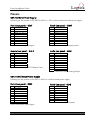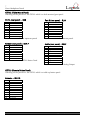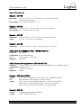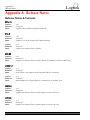
1
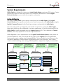
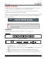
Logitek Logitek Electronic Systems Utility Panel User's Manual Revision 1.0 Sep 2005 Logitek Electronic Systems, Inc. 5622 Edgemoor Drive Houston, Texas 77081 Tel Fax 713-664-4470 713-664-4479 Email [email protected] Web www.logitekaudio.com Contents © 2005 Logitek Electronic Systems, Inc Notice Every effort has been made to supply complete and accurate information. However, Logitek Electronic Systems, Inc. assumes no responsibility for its use, nor any infringement of patents or other rights of third parties, which would result. Worldwide rights reserved. Except for your own personal use, no part of this publication may be stored in a retrieval system, transmitted or reproduced in any way, including but not limited to photocopy, photograph, magnetic or other record, without the prior agreement and written permission of Logitek Electronic Systems, Inc. Logitek is a trademark of Logitek Electronic Systems, Inc. All other trademarks acknowledged. All specifications are subject to change without notice. 1 Introduction Logitek Document Revisions Date September 2005 Revision 1.0 Author Paul Dengate Logitek Utility Panel User's Manual Notes First release of Utility Panel manual 1 1 Introduction Logitek Contents 1 Introduction ........................................................................................................................... 3 About this Manual............................................................................................................... 3 About Utility Panels............................................................................................................. 4 System Requirements.......................................................................................................... 5 2 Unpacking .............................................................................................................................. 6 Parts List ............................................................................................................................. 6 Unpacking .......................................................................................................................... 6 3 Common Information ............................................................................................................ 7 About Device & Bus Addressing .......................................................................................... 7 Daisy-chaining Panels.......................................................................................................... 7 Wiring ................................................................................................................................ 8 4 BTN-12 Panel .......................................................................................................................... 9 Installation .......................................................................................................................... 9 Configuration .................................................................................................................... 10 Operation ......................................................................................................................... 12 Device & Bus Addressing .................................................................................................. 12 Pinouts ............................................................................................................................. 14 Specifications .................................................................................................................... 15 5 COM-12 Panel ...................................................................................................................... 16 Installation ........................................................................................................................ 16 Configuration .................................................................................................................... 17 Operation ......................................................................................................................... 19 Device & Bus Addressing .................................................................................................. 19 Pinouts ............................................................................................................................. 20 Specifications .................................................................................................................... 21 6 RTE-3 & RTE-XY ..................................................................................................................... 22 Installation ........................................................................................................................ 22 Configuration .................................................................................................................... 23 Operation ......................................................................................................................... 27 Device & Bus Addressing .................................................................................................. 28 Pinouts ............................................................................................................................. 29 Specifications .................................................................................................................... 29 7 Guest Headphone Panels .................................................................................................... 30 Installation ........................................................................................................................ 30 Configuration .................................................................................................................... 33 Operation ......................................................................................................................... 35 Device & Bus Addressing .................................................................................................. 35 Pinouts ............................................................................................................................. 37 Specifications .................................................................................................................... 39 Appendix A Release Notes....................................................................................................... 40 Release Notes & Versions .................................................................................................. 40 2 Logitek Utility Panel User's Manual 1 Introduction Logitek 1 Introduction About this Manual This manual describes the installation and operation of the Logitek utility panels, including COM-12, BTN-12, RTE-3, RTE-XY and Guest Headphone panels. Intended Audience This manual is aimed at Engineers and Technical Operators responsible for installing, configuring and supporting a Logitek Console Router System that uses any of these utility panels. In the context of a system installation, or to become familiar with the entire Logitek Console Router System, the reader should also reference: ¾ ¾ ¾ ¾ Audio Engine Installation & Operation Manual AEConfig User’s Manual Supervisor User’s Manual CommandBuilder User’s Manual Manual Conventions The following conventions are used in this manual: This text indicates a menu choice to be made, with an arrow separating a multi-level selection, eg Control Panel ¾ Users & Passwords. This can be a menu choice in a Logitek application, or within Windows. ¬ Indicates a “see-also” section in this manual, or another Logitek manual. The exclamation symbol signifies an important note or critical information. This text represents a command, script block example, instruction to be typed, or directory path. TIP: A useful tip from our knowledge base! Logitek Utility Panel User's Manual 3 1 Introduction Logitek About Utility Panels Logitek provides various control panels that connect to your Audio Engines and integrate into your system. These panels are fully configurable to suit the specific requirements of your facility. The current range of Utility Panels includes: BTN-12 A 1 RU button panel with 12 buttons/lamps, plus 18 GPI inputs and outputs. COM-12 A 1 RU button panel with 12 buttons/lamps, plus integrated mic preamp and speaker amp for intercom purposes. Buttons can be programmed all as intercom stations, or for mixed functions. GST-20/22/23 An integrated monitoring selector, mic on/off/mute control and headphone amplifier, designed for use by studio guests. The GST-22 is a desk mounted headphone controller. The GST-20 is a 1RU rack mount version. The GST-23 is a remote 6 button panel for additional control applications. RTE-3 A 3 output router controller, designed for controlling record outputs and other destination feeds in a studio or equipment room. RTE-XY An X-Y version of the RTE-3, which allows controlling multiple destinations on an Audio Engine. 4 Logitek Utility Panel User's Manual 1 Introduction Logitek System Requirements Utility Panels are designed to connect to a Logitek Audio Engine running any DSP version. Certain features may require a certain level of DSP or AE controller card firmware. Contact Logitek Electronic Systems or your reseller if you require confirmation. System Architecture Put simply, a Utility Panel is just a remote control panel for the Audio Engine. Like Logitek Console Surfaces, these panels send and receive control commands to the Audio Engine using the Logitek Command Protocol, with all audio processing occurring inside the Audio Engine. The router style panels are designed to control audio crosspoints on a particular Audio Engine. Button style panels are fully configurable to suit user requirements. As such the functionality of the Utility Panels is usually dependant upon the Logitek Supervisor PCs. This is different to Console Surfaces, which only require PCs to execute scripts and macros. Whilst Supervisor is not a requirement to run a Logitek Console Router System, most systems are now sold with this PC suite, as it unlocks the true power of the Logitek system. Programmable button panels require scripting using CommandBuilder. The functionality for these buttons is then executed by Supervisor. If these buttons are performing on-air critical functions, such as delay control or studio switching, then running a Dual Supervisor configuration is highly recommended. Surfaces are remote control panels for Audio Engine Surfaces Audio Engines process Audio and GPI control events Audio Engines Console Surfaces AE1 Control Panels Supervisor executes scripts and provides gateway to IP world Supervisor PCs Client PCs Software vTools Supervisor PC Main Software vTools Software vTools Fibre Audio Network Console Surfaces Control Panels AE2 Serial Comms Client PCs interact with Audio Engines via Supervisor Software vTools Supervisor PC Backup (optional) Serial Comms Software vTools Software vTools TCP/IP Serial TCP/IP Fibre Figure 1 - Logitek System Architecture Logitek Utility Panel User's Manual 5 2 Unpacking Logitek 2 Unpacking This section details what you should do when unpacking your newly arrived Utility Panel. Parts List The exact list of parts received will vary depending on panels ordered, but should generally include: Rack Mount Panels ¾ Utility Panel in 19” rack mount housing ¾ Integrated internal switch mode power supply ¾ Utility Panels User’s Manual Guest Headphone Panels ¾ ¾ ¾ ¾ ¾ GST-20 (1RU) power supply and headphone panels as ordered GST-21 (wall mount) power supply(s) as ordered GST-22 headphone panels as ordered GST-23 remote button panels as ordered Utility Panels User’s Manual Cabling is not supplied, as this generally needs to be integrated into facility wiring. Unpacking Carefully unpack the cartons whilst looking for any signs of shipping damage. You may wish to save the shipping cartons until the operation of the system is verified. Report any damage to the shipping carrier immediately. Verify that the contents of each box match the packing list and report any discrepancies immediately to Logitek in writing. Contacting Logitek In the event of a shipping problem, you can contact Logitek Electronic Systems in several ways: U.S. Mail Telephone Fax Email Website 6 Logitek Electronic Systems, Inc. 522 Edgemoor Drive Houston, Texas 77081 877-231-5870 713-664-4470 (outside U.S. and Canada) 713-664-4479 [email protected] www.logitekaudio.com Logitek Utility Panel User's Manual 3 Common Information Logitek 3 Common Information The rest of this manual has one chapter for each Utility Panel that is available from Logitek. Below is information that is relevant to all panels, and therefore is not duplicated in each chapter. About Device & Bus Addressing Each device (such as a fader input or button panel) requires its own Device Number. Within that device, each button, lamp and feature has a Bus Number. Together, the Device and Bus Numbers allow the Audio Engine and Surface to communicate. When configuring the programmable buttons in CommandBuilder, you will require the Device Number and Bus Number for each button or lamp. The information in each chapter will help you determine the addressing required for the particular panel. Each Utility Panel includes device addressing wheels at the rear, which allow you to set the Device Number. In the case of panels that are associated with a particular output (or group of outputs), we recommend you use the Device Number of that output (this can be found in the AEConfig Output Page for the particular Audio Engine.) If using an AE-C6 Audio Engine Controller Card, ports 4-6 are recommended for the connection of Utility Panels. As the panels do not require allocation of DSP resources, ports 1-3 can be kept free for mixer surfaces. The AE-C2 card only has 3 ports available. The Route-3 panel has two modes of addressing, which are both covered in the Route-3 chapter. Daisy-chaining Panels Most panels support the ability to daisy chain to other panels downstream. This reduces the amount of wiring and the amount of Audio Engine ports required when panels are located in proximity. This is particularly useful for the AE-C2 card, which only has three surface ports per Audio Engine. However, as each panel is “active” in the circuit, a failure of an upstream panel will render all downstream panels inoperable. This should be considered in redundancy planning. IO8D IO24A Net-A AE-C6 Reset Master Sharc Lone Attack Sharc RX Lock RX Lock Audio Engine COM12 BTN12 ROUTE3 ROUTEXY Figure 2 - Example of daisy-chaining Utility Panels Logitek Utility Panel User's Manual 7 3 Common Information Logitek Wiring Utility Panels share a common connection and wiring scheme. Wiring from an Audio Engine to a panel will depend on the type of Controller Card in use. Both are shown below, as well as wiring between daisy-chained panels. The Guest Headphone Panel wiring is detailed in Chapter 7. Wiring Twisted pair data cable should be used – CAT5 (or greater) is suitable. The RS485 +/- transmission lines should be on a pair together. If using shielded cable, Pin 5 on the DB9 should be connected to shield/drain. With unshielded cable, use one half of a pair. As the transmission is balanced, shielded cable is not necessary, unless in very high RF environments. TIA-568B wiring colors are shown. Pair 1 Cue is not required for Utility Panels, but can be wired as per Surface cables for consistency. AE-C2 to Panel Wiring from an AE-C2 card is the same as a mixer surface. The first pair (cue), is not required, but can still be wired. A Port 3 connection requires Pins 3 & 8 reversed at one end (see AE-C2 wiring). Figure 3 - AE-C2 to Panel wiring AE-C6 to Panel For an AE-C6, we suggest using the TIA-568A/B color code at the RJ45, and wiring the DB9 to suit. The first pair (cue), is not required, but can still be wired (as per AE-C6 to console wiring). Figure 4 - AE-C6 to Panel wiring Panel to Panel For daisy-chaining panels together, follow the same procedures as AE-C2 to Panel, listed above. Figure 5 - Panel to Panel wiring 8 Logitek Utility Panel User's Manual 4 BTN-12 Panel Logitek 4 BTN-12 Panel The BTN-12 panel is a rack mount panel with 12 user-programmable buttons. It also features 18 GPI inputs and outputs to provide additional GPI interfacing where required. The BTN-12 is a basic control panel, and does not include any audio input or output. For an intercom panel, we recommend using the COM-12 panel. All buttons are fully programmable, and can be used for a combination of routing, intercom or other functions. The lamps in the button are a single color (red) LED, which supports solid illumination and a single flash speed. Figure 6 - BTN-12 This chapter applies to BTN-12 models that have address wheels on the rear, and buttons in three groups of four, as shown above. For BTN-12 units with all 12 buttons spaced equally, and no address wheels, please refer to the manual that shipped with the unit. Installation The BTN-12 is designed for mounting in a standard 19” rack, occupying 1 RU. Connections Figure 7 - BTN-12 Front View Figure 8 - BTN-12 Rear View ¾ The MAINS connector is an IEC style inlet connector. ¾ Port A is a DB9 female connector. This connects to the Audio Engine, or another upstream panel. ¾ Port B is a DB9 female connector. This connects to a downstream panel (optional). ¾ GPI IN is a DB37 female connector. This connects to the BTN-12 GPI inputs (optional). ¾ GPI OUT is a DB37 female connector. This connects to the BTN-12 GPI outputs (optional). Logitek Utility Panel User's Manual 9 4 BTN-12 Panel Logitek Configuration Device Allocation The two wheels on the back of the unit are used to set its Device Number. This sets the addressing between the Utility Panel and Audio Engine. The valid range is from 01 to FF, although not all addresses in this range are usable. If the BTN-12 will be used as a 12x1 router (or similar), we suggest that you connect it to the Audio Engine that is responsible for the audio the BTN-12 is controlling, and use the Device Number of that Audio Engine Output. As the BTN-12 uses BUS 1-12 for its lamps, the Device Number allocated should not conflict with Fader or DSP Crosspoints, otherwise the BTN-12 and DSP functions will clash. Using the BTN-12 with an output Device Number does not cause any conflict on a v3 Audio Engine. AEConfig The BTN-12 panel does not need to be shown on AEConfig’s Hardware Page, as this page is used to setup mixer surfaces that use DSP resources. If you are using the BTN-12 panel as an Intercom controller (with separate mic and speaker), we suggest you follow the AEConfig notes for the COM-12 intercom unit. If you are using the BTN-12 purely as a button/GPI control panel, with no associated audio, there is nothing to configure in AEConfig. ¬ For more information on Engine I/O and routing, see the AEConfig User’s Manual. Route Mode The BTN-12 defaults to “GPI Mode”, which sets it to send button presses and GPI closures to the Audio Engine. If Triggers are programmed against the relevant bus number, an event will occur. The BTN-12 also supports “Route Mode”, which turns the unit into a 12x1 Router. In this mode, each button sends the required Route command to the Audio Engine. To configure for “Route Mode”, you need to allocate an output in AEConfig, and assign up to 12 inputs ticks to that output. These will be uploaded to the BTN-12 when it goes into Route Mode. The order of the inputs is alphabetical, based on the Surface Label assigned to the input in AEConfig. It is not possible to change the order of the inputs. If more flexible input assignment is required, we recommend using the 12x1 Router Triggers detailed in the CommandBuilder manual. To use Route Mode, you will need to send a BUS32 ON command to the BTN-12 in your Trigger Table. The Init Trigger is a good place to send that command. 10 Logitek Utility Panel User's Manual 4 BTN-12 Panel Logitek CommandBuilder Triggers If using a BTN-12 in Route Mode, no programming in CommandBuilder is necessary. If you wish to use a BTN-12 to do anything else, you must define a set of Triggers in CommandBuilder. Possible Triggers for a BTN-12 include: ¾ Button (switch) BUS ON ¾ Button (switch) BUS OFF ¾ GPI Input BUS ON ¾ GPI Input BUS OFF Possible Commands for a BTN-12 include: ¾ Lamp BUS ON ¾ Lamp BUS OFF ¾ Lamp FLASH ¾ GPI Output BUS ON ¾ GPI Output BUS OFF ¾ GPI Output PULSE The Triggers and Commands will require the following information: 1. Audio Engine Number (the AE the BTN-12 is connected to). 2. Device Number (based on the Port and/or Address wheels on the back). 3. Bus Number (a list of BTN-12 Bus Numbers follows in the Device & Addressing section). Possible applications for a BTN-12 include: ¾ 12x1 Route Switcher (or other combinations based on available buttons) ¾ Intercom / Talkback panel ¾ Remote start panel ¾ Monitoring switcher panel ¬ For Trigger examples, refer to the CommandBuilder User’s Manual Part C. Logitek Utility Panel User's Manual 11 4 BTN-12 Panel Logitek Operation Operation of the BTN-12 varies depending on its programming. ¾ The 12 push buttons can be used for push-to-talk, toggle or grouped push-once functions ¾ The BTN-12 can also be programmed in Route mode, where it becomes a 12x1 router. ¾ The lamps in the buttons will light if programmed to do so. They can also be set to flash (single speed). In Route mode, a single lamp will indicate the currently routed source. Device & Bus Addressing Device Numbers Device addressing is set by the number wheels on the back of the BTN-12. A single Device Number is used for both lamps and buttons, with the Bus Number distinguishing which is which. Bus Numbers Bus numbering is fixed by the BTN-12 firmware and is not configurable. The following Bus Numbers are used. Button/GPI 1 2 3 4 5 6 7 8 9 10 11 12 13 14 15 16 17 18 12 Lamp Bus 01 Bus 02 Bus 03 Bus 04 Bus 05 Bus 06 Bus 07 Bus 08 Bus 09 Bus 10 Bus 11 Bus 12 - Switch Bus 17 Bus 18 Bus 19 Bus 20 Bus 21 Bus 22 Bus 23 Bus 24 Bus 25 Bus 26 Bus 27 Bus 28 - GPI Out Bus 81 Bus 82 Bus 83 Bus 84 Bus 85 Bus 86 Bus 87 Bus 88 Bus 89 Bus 90 Bus 91 Bus 92 Bus 93 Bus 94 Bus 95 Bus 96 Bus 97 Bus 98 GPI In Bus 49 Bus 50 Bus 51 Bus 52 Bus 53 Bus 54 Bus 55 Bus 56 Bus 57 Bus 58 Bus 59 Bus 60 Bus 61 Bus 62 Bus 63 Bus 64 Bus 65 Bus 66 Logitek Utility Panel User's Manual 4 BTN-12 Panel Logitek Commands Supported The BTN-12 supports the following Logitek Protocol commands. Dn Bn Sc Device Number Bus Number Source Device (01xx) Command B1 (flash) B2 (bus on) B3 (bus off) B4 (route) Trigger Command FLASH BUS ON BUS OFF ROUTE Example <02><04><B1><Dn><Bn><03> <02><03><B2><Dn><Bn> <02><03><B3><Dn><Bn> <02><04><B4><Dn><01><Sc> Notes Fully supported Fully supported Fully supported Must be in Route Mode The BTN-12 also supports the following utility commands for setting the panel’s mode, and performing other functions. Command Clear All Trigger Command BUS 33 ON Example Set GPI Mode BUS 32 OFF <02><03><B3><Dn><20> Set Route Mode BUS 32 ON <02><03><B2><Dn><20> <02><03><B2><Dn><21> Notes Clear all LED’s in the current mode, where Dn is the device number. Select GPI mode, where Dn is the device number of the unit. Select Route mode, where Dn is the device number of the unit.. The BTN-12 does not support variable brightness illumination in its lamps. These will be ignored. Logitek Utility Panel User's Manual 13 4 BTN-12 Panel Logitek Pinouts Port A (rear panel) – DB9F Port B (rear panel) – DB9F Pin 1 2 3 4 5 6 7 8 9 Pin 1 2 3 4 5 6 7 8 9 Connection No connect RS485 RX+ (Pair 2) RS485 TX+ (Pair 3) No connect Ground No connect RS485 RX- (Pair 2) RS485 TX- (Pair 3) No connect Port A connects to AE or upstream panel Connection No connect RS485 TX+ (Pair 2) RS485 RX+ (Pair 3) No connect Ground No connect RS485 TX- (Pair 2) RS485 RX- (Pair 3) No connect Port B connects to downstream panels GPI In (rear panel) – DB37F GPI Out (rear panel) – DB37F Pin 1 2 3 4 5 6 7 8 9 10 11 12 13 14 15 16 17 18 19 Pin 1 2 3 4 5 6 7 8 9 10 11 12 13 14 15 16 17 18 19 14 Connection Input 1 Input 2 Input 3 Input 4 Input 5 Input 6 Input 7 Input 8 Input 9 Input 10 Input 11 Input 12 Input 13 Input 14 Input 15 Input 16 Input 17 Input 18 No Connect Pin 20 21 22 23 24 25 26 27 28 29 30 31 32 33 34 35 36 37 Connection Ground Ground Ground Ground Ground Ground Ground Ground Ground Ground Ground Ground Ground Ground Ground Ground Ground Ground Connection Relay 1 Relay 2 Relay 3 Relay 4 Relay 5 Relay 6 Relay 7 Relay 8 Relay 9 Relay 10 Relay 11 Relay 12 Relay 13 Relay 14 Relay 15 Relay 16 Relay 17 Relay 18 No Connect Pin 20 21 22 23 24 25 26 27 28 29 30 31 32 33 34 35 36 37 Connection Relay 1 Relay 2 Relay 3 Relay 4 Relay 5 Relay 6 Relay 7 Relay 8 Relay 9 Relay 10 Relay 11 Relay 12 Relay 13 Relay 14 Relay 15 Relay 16 Relay 17 Relay 18 Logitek Utility Panel User's Manual Logitek BTN-12 Panel Specifications General 19” W x 1.75” H x 7.5” D (482.6 mm x 44.5 mm x 190.5 mm) Occupies 1 RU rack space Power Supply 110 - 230 VAC, 50/60 Hz, 15 W. Input voltage is switch selectable inside unit. Dimensions GPI Inputs Number Interface Type 18 Rear panel DB37 Female Input+ pins are driven to 5 VDC through a 10K ohm resistor. Pull to ground to activate. GPI Outputs Number Interface Type 18 Rear panel DB37 Female Relays have a single pole, single throw contact rated at a maximum of 50VDC @ 500 mA Control Buttons Lamps Comms 12 lighted buttons with legend holding caps Integrated into button, supports solid illumination and one flash speed 2 COM ports, RS485 Multiple units can be daisy chained together Logitek Utility Panel User's Manual 15 5 COM-12 Panel Logitek 5 COM-12 Panel The COM-12 panel is a rack mount intercom unit. It features an internal mic pre-amp and speaker, with a front-mounted XLR for connection of your choice of intercom mic. The COM-12 front panel buttons are arranged in two rows of 6. All buttons are fully programmable, and can be used for a combination of intercom, routing, or other functions. The lamps in the button are a single color (red) LED, which supports solid illumination and three flash speeds. Figure 9 - COM-12 with optional AKG D58E and Boom Arm Installation The COM-12 is designed for mounting in a standard 19” rack, occupying 1 RU. Connections Figure 10 - COM-12 Front View Figure 11 - COM-12 Rear View ¾ ¾ ¾ ¾ ¾ ¾ The MAINS connector is an IEC style inlet connector. Port A is a DB9 female connector. This connects to the Audio Engine, or an upstream panel. Port B is a DB9 female connector. This connects to a downstream panel (optional). Preamp Out is a male XLR connector. This is a line level output of the internal mic preamp. Speaker In is a female XLR connector. This is a line level input to the speaker amp. The front panel has a female XLR connector for attaching a microphone. As the type of microphone depends on user preference, this is not included. The COM-12 accepts a dynamic microphone, with an adjustable gain control. Microphone A dynamic microphone is required for the front panel. Any dynamic intercom type of microphone should provide acceptable results. The COM-12 has been tested with an AKG D58E microphone. 16 Logitek Utility Panel User's Manual Logitek COM-12 Panel Configuration Device Allocation The two wheels on the back of the unit are used to set its Device Number. This sets the addressing between the Utility Panel and the Audio Engine. The valid range is from 01 to FF, although not all addresses in this range are usable. For a COM-12, we suggest that you connect it to the Audio Engine that is responsible for the audio to/from the COM-12, and use the Device Number of the Audio Engine Output that feeds the COM-12’s intercom input. Gain Control The gain pot on the rear of the panel is used to set the mic pre-amp gain. A small screwdriver can be used to make adjustments. For consistency between multiple COM-12 panels, you may wish to inject tone at a mic level that reflects the sensitivity of the mic in use, and adjust to suit. Gain can also be adjusted at the Audio Engine inputs and outputs, however it is always better to ensure the COM-12 is within acceptable range first. The front panel of the COM-12 has a speaker volume allowing the user to adjust the incoming level. AEConfig The COM-12 panel does not need to be shown on AEConfig’s Hardware Page, as this page is used to setup mixer surfaces that use DSP resources. The COM-12 uses output routes and not DSP mixing. The COM-12 will require a mono Input and Output on an Analog IO card. For example, if the COM-12 is used in a Master Control Room, the following naming could be used: Label Unique Name MCR Mic MCR T/B MCR Talkback Mic MCR Talkback Output In a multi-engine system, the Intercom Mic input should be allocated to the Fibre Network so that intercom audio can be routed to any Audio Engine. The output can be allocated no source on the Surface Settings page, or a default “silence” source if one is used. On a version 3.x and above Audio Engine, intercom audio to the COM-12 can be routed directly to the Output that feeds it, or a DSP Crosspoint can be used. The latter provides for gain control, and audio processing if DSP crosspoints on a SharcAttack DSP card are available. In common practice, routing directly to the Output is usually sufficient, and the most simple option. ¬ For more information on Engine I/O and routing, see the AEConfig User’s Manual. Logitek Utility Panel User's Manual 17 5 COM-12 Panel Logitek CommandBuilder Triggers A COM-12 requires Triggers to perform the desired functions. These are scripted in CommandBuilder then uploaded and executed by Supervisor. The exact Triggers written for a COM-12 depend on required functionality. As the COM-12 is primarily designed as an Intercom panel, we suggest you review the Intercom examples in the CommandBuilder manual. Possible Triggers for a COM-12 include: ¾ Button (switch) BUS ON ¾ Button (switch) BUS OFF Possible Commands for a COM-12 include: ¾ Lamp BUS ON ¾ Lamp BUS OFF ¾ Lamp FLASH The Triggers and Commands will require the following information: 1. Audio Engine Number (the AE the COM-12 is connected to). 2. Device Number (based on the Port and/or Address wheels on the back). 3. Bus Number (a list of COM-12 Bus Numbers follows in the Device & Addressing section). Whilst the COM-12 is designed to be an Intercom/Talkback panel, available buttons can still be programmed to perform other tasks, such as: ¾ Route switching ¾ Remote starts ¾ Monitoring switching ¾ Delay control ¬ For detailed Trigger examples, refer to the CommandBuilder User’s Manual Part C. 18 Logitek Utility Panel User's Manual Logitek COM-12 Panel Operation Operation of the COM-12 varies depending on its programming: ¾ The 12 push buttons can be used for push-to-talk, toggle or grouped push-once functions ¾ Lamps will light if programmed to do so. They can also flash in three different speeds. ¾ The front-panel volume control can be used to adjust the incoming audio level. Device & Bus Addressing Device Numbers Device addressing is set by the number wheels on the back of the COM-12. A single Device Number is used for both lamps and buttons, with the Bus Number distinguishing which is which. Bus Numbers Bus numbering is fixed by the COM-12 firmware and is not configurable. The following Bus Numbers are used. Buttons are left to right, 1-6 on the top row, and 7-12 on the bottom row. Button 1 2 3 4 5 6 7 8 9 10 11 12 Switch Bus 51 Bus 52 Bus 53 Bus 54 Bus 55 Bus 56 Bus 57 Bus 58 Bus 59 Bus 60 Bus 61 Bus 62 Lamp Bus 31 Bus 32 Bus 33 Bus 34 Bus 35 Bus 36 Bus 37 Bus 38 Bus 39 Bus 40 Bus 41 Bus 42 Commands Supported The COM-12 supports the following Logitek Protocol commands. Dn Bn Fr Fn Device Number Bus Number Flash Rate (02= slow, 03 = medium, 05 = fast) Flash Number (01-255, 00 = continuous). Command B1 (flash) Trigger Command FLASH Example Notes Supported in v1.3 Not supported as yet * B2 (bus on) BUS ON Fully supported B3 (bus off) BUS OFF Fully supported * Where a 5-byte B1 is sent, the COM-12 v1.3 will use the flash rate but ignore flash number. <02><04><B1><Dn><Bn><Fr> <02><05><B1><Dn><Bn><Fr><Fn> <02><03><B2><Dn><Bn> <02><03><B3><Dn><Bn> The COM-12 does not support variable brightness illumination in its lamps. These will be ignored. Logitek Utility Panel User's Manual 19 5 COM-12 Panel Logitek Pinouts Port A (rear panel) – DB9F Port B (rear panel) – DB9F Pin 1 2 3 4 5 6 7 8 9 Pin 1 2 3 4 5 6 7 8 9 Connection No connect RS485 RX+ (Pair 2) RS485 TX+ (Pair 3) No connect Ground No connect RS485 RX- (Pair 2) RS485 TX- (Pair 3) No connect Port A connects to AE or upstream panel Connection No connect RS485 TX+ (Pair 2) RS485 RX+ (Pair 3) No connect Ground No connect RS485 TX- (Pair 2) RS485 RX- (Pair 3) No connect Port B connects to downstream panels Preamp Out (rear panel) – XLR M Speaker In (rear panel) – XLR F Pin 1 2 3 Pin 1 2 3 Connection Ground Hot Cold Line Level Connection Ground Hot Cold Line Level Mic In (front panel) – XLR F Pin 1 2 3 Connection Ground Hot Cold Mic Level 20 Logitek Utility Panel User's Manual COM-12 Panel Logitek Specifications General 19” W x 1.75” H x 7.5” D (482.6 mm x 44.5 mm x 190.5 mm) Occupies 1 RU rack space Power Supply 110 - 230 VAC, 50/60 Hz, 15 W Dimensions Audio Input for Speaker Connector Configuration Level Impedance Female XLR Active Balanced 0 dBu normal, +24 dBu max 25 K Ohms Audio Output from Microphone Connector Configuration Level Impedance Male XLR Active Balanced 0 dBu normal, +24 dBu max 10 Ohms Control Buttons Lamps Comms 12 lighted buttons with legend holding caps Integrated into button, supports solid illumination and three flash speeds 2 COM ports, RS485 Multiple units can be daisy chained together Logitek Utility Panel User's Manual 21 6 RTE-3 & RTE-XY Logitek 6 RTE-3 & RTE-XY The RTE-3 and RTE-XY panels provide routing control for an Audio Engine. These are commonly implemented as studio record source selectors, or MCR utility routers. The RTE-3 allows access to 3 output selections, while the RTE-XY can control all outputs on a single Audio Engine. Both are configurable in AEConfig to only allow certain sources or destinations. A backlit LCD screen shows the user the current routes, with user-configurable labels. Both models share the same physical hardware, although firmware and front panel printing distinguish their operation. Figure 12 - RTE-3 Figure 13 - RTE-XY Installation The RTE-3 and RTE-XY are designed for mounting in a standard 19” rack, occupying 1 RU. Connections Figure 14 - RTE-3 & RTE-XY Front View Figure 15 - RTE-3 & RTE-XY Rear View ¾ The MAINS connector is an IEC style inlet connector. ¾ Port A is a DB9 female connector. This connects to the Audio Engine, or another upstream panel. ¾ Port B is a DB9 female connector. This connects to a downstream panel (optional). 22 Logitek Utility Panel User's Manual Logitek RTE-3 & RTE-XY Configuration Device Allocation The two wheels on the back of the unit are used to set its Device Number. This sets the addressing between the Utility Panel and Audio Engine. The valid range is from 01 to FF. RTE-3 Device Allocation The RTE-3 supports two methods of device allocation: ¾ Using DSP Crosspoints on Audio Engine Port 1, 2 or 3 ¾ Using output routes on any Audio Engine Port (older units may require firmware update) Feature Allowed Ports Source allocation list Address settings Number of Panels per port DSP Options Feed Crosspoint to multiple outputs Feed Crosspoint to fiber network Crosspoint mode 1, 2 or 3 (AE-C2 & AE-C6) Set in AEConfig Surface Settings for Port 1, 2 or 3. Must be setup in Hardware Page. Set Device Number to match Crosspoints on Surface Settings Tab (eg 01 for first panel, 04 for second panel, etc). Limited by available Crosspoints Can set Crosspoint gain & mode in Supervisor or Triggers Yes – DSP Crosspoint can be assigned to multiple I/O card outputs Yes – allocate DSP Crosspoint to NetA output Output mode 1-3 (AE-C2) / 1-6 (AE-C6) Set in AEConfig Surface Settings ¾ Output Selections. Don’t show on Hardware Page. Set Device Number to match first output in AEConfig. Three outputs must have sequential Device Numbers in AEConfig output page. Limited by available outputs No DSP – only output routing No No Output routing provides a simple way to configure the Route 3. In this mode, any port may be used (provided no surface is shown in AEConfig for this port), and any number of panels may be daisy chained. If you are unsure, this is the recommended configuration. DSP Crosspoints provide some additional features, such as the ability to use audio processing on a Crosspoint, allocate a Crosspoint to multiple outputs, or switch an output to the fiber-network NetA card. RTE-XY Device Allocation The RTE-XY provides access to any number of destinations on a particular Audio Engine. It can be allocated any Device Number that corresponds to an output route in AEConfig. As AEConfig can be used to set the allowed destinations for a RTE-XY panel, we suggest allocating an output Device Number that relates to the RTE-XY (eg a Monitoring output). TIP: The ability to allow only specified destinations on a RTE-XY requires a version of AEConfig dated May 2005 or later, and v3.3 or later of the RTE-XY. In prior versions or either AEConfig or RTE-XY software, the panel has access to all destinations. Logitek Utility Panel User's Manual 23 6 RTE-3 & RTE-XY Logitek AEConfig Configuration To setup a RTE-3 using DSP Crosspoints: 1. On the AEConfig Hardware Config page, allocate a “Router” to Port 1, 2 or 3. 2. Go to the AEConfig Surface Settings page and select the port you allocated in Step 1. 3. You will now see a series of available DSP Crosspoints, labeled “CP1 St” and so on. 4. The RTE-3 Device Number should be allocated to available DSP Crosspoints on this port. For example, setting the wheels to “01” will tell the RTE-3 to use Crosspoints 1-3. Please note, some higher numbered Crosspoints are mono only. 5. Additional panels can be allocated Device Numbers and Crosspoints as per step 4. 6. You can now allocate the allowed Source ticks to each of the Crosspoints as required. 7. Go to the AEConfig Surface Settings page and select the page for the port you are using. 8. The DSP Crosspoints used above can now be allocated to the desired audio outputs. It is possible to allocate these to NetA channels if required. This assumes you have already added the required outputs to your config. See the screenshot below for tick mark examples. 9. Once your settings have been made, your new config can be uploaded to the Audio Engine. Figure 16 - AEConfig showing Output Selections for Router Surface 24 Logitek Utility Panel User's Manual Logitek RTE-3 & RTE-XY To setup a RTE-3 using Output Routes: 1. On the AEConfig Hardware Config page, ensure no surface is allocated to the port you will be using for the RTE-3. 2. Go to the AEConfig Outputs page. The outputs for each RTE-3 should be added in order, so that they receive sequential Device Numbers. 3. The RTE-3 Device Number should be set to the Device Number of the first output of the group. For example, setting the wheels to “6E” will tell the RTE-3 to control outputs 6E, 6F and 70. The Device Number can be viewed by editing the Output line. 4. Go to the AEConfig Surface Settings page and select the Output Selections page. 5. You can now allocate the allowed Source ticks to each of the Outputs as required. The Audio Engine only supports routing to I/O card outputs – you cannot route to NetA channels using this method. See the screenshot below for tick mark examples. 6. Additional panels can be added by repeating Steps 1-5. 7. Once your settings have been made, your new config can be uploaded to the Audio Engine. Figure 17 - AEConfig Output Selections for output destination. Logitek Utility Panel User's Manual 25 6 RTE-3 & RTE-XY Logitek To setup a RTE-XY: 1. On the AEConfig Hardware Config page, ensure no surface is allocated on the port you will be using for the RTE-XY. On an AE-C6 card you can use Ports 4, 5, or 6 if desired. 2. The RTE-XY Device Number should be set to the Device Number of a relevant/related Output (eg a nearby monitoring point). This Output’s column is used to set the allowed Destinations for that RTE-XY panel. 3. Set the RTE-XY wheels to match the output’s Device Number (see Output Settings page). 4. Go to AEConfig Surface Settings and select the Output Selections page. 5. At the bottom of the grid you will see a blue section listing all Destination rows. Find the relevant RTE-XY Output column, then place tick marks for each allowed Destination. An allowed Destination is indicated by a tick surrounded by the letters “X” and “Y”. 6. The allowed Sources for each Destination are set by the red/green ticks in the top section. Sources should be allowed by placing a tick in the column for each required Destination. 7. Additional panels can be added by repeating Steps 1-4. Each RTE-XY panel requires its own output Device Number, so its allowed Destinations can be independently set in AEConfig. 8. Once your settings have been made, your new config can be uploaded to the Audio Engine. Figure 18 - AEConfig showing Output Selections for Route XY ¬ For more information on Engine I/O and routing, see the AEConfig User’s Manual. 26 Logitek Utility Panel User's Manual RTE-3 & RTE-XY Logitek CommandBuilder Triggers The RTE-3 and RTE-XY do not require Triggers to be programmed. In addition to audio routing, the RTE-3 can be used to present question screens to the user. ¬ See the CommandBuilder User’s Manual for information on question screens. Operation Route 3 (RTE-3) ¾ Press the CH1, CH2, or CH3 button to edit the required destination. ¾ Use the SELECT wheel to choose the desired input. ¾ Press the TAKE button to confirm and perform the route. Route XY (RTE-XY) The Route XY has three modes of operation: 1. Locked – all front panel control is disabled (except for unlock function). 2. View – allows the route selections to be viewed but not changed. 3. Change – full view and change permissions. To change the Route XY mode: ¾ Press the MODE button ¾ Use the SELECT wheel to choose the desired mode ¾ Press CONFIRM to accept the new mode The view a route: ¾ ¾ ¾ ¾ Select VIEW or CHANGE mode (as above) Press the DEST button Use the SELECT wheel to cycle through the allowed destinations The source will be displayed on screen as you move through the list The change a route: ¾ ¾ ¾ ¾ ¾ ¾ Select CHANGE mode (as above) Press the DEST button Use the SELECT wheel to cycle through to the desired destination Press the SOURCE button Use the SELECT wheel to cycle through to the desired source Press the CONFIRM button to perform the route Logitek Utility Panel User's Manual 27 6 RTE-3 & RTE-XY Logitek Device & Bus Addressing Device Numbers Device addressing is set by the number wheels on the back of the RTE-3 or RTE-XY. For a RTE-3, the Device Number on the wheels sets the CH1 router. CH2 and CH3 use the next consecutive Device Numbers. When using output routing in AEConfig, you must setup the 3 outputs to be used on the RTE-3 in order, so that AEConfig allocates consecutive Device Numbers. Bus Numbers The RTE-3 and RTE-XY do not utilize bus numbers for route control. Commands Supported The RTE-3 and RTE-XY support the following Logitek Protocol commands. Dn Bs Sd Device Number Bus Number Source Device (01xx) Command B4 (route) Trigger Command ROUTE 28 Example <03><B4><Dn><01><Sd> Notes Device Number determined by which channel is being routed. Logitek Utility Panel User's Manual Logitek RTE-3 & RTE-XY Pinouts Port A (rear panel) – DB9F Port B (rear panel) – DB9F Pin 1 2 3 4 5 6 7 8 9 Pin 1 2 3 4 5 6 7 8 9 Connection No connect RS485 RX+ (Pair 2) RS485 TX+ (Pair 3) No connect Ground No connect RS485 RX- (Pair 2) RS485 TX- (Pair 3) No connect Port A connects to AE or upstream panel Connection No connect RS485 TX+ (Pair 2) RS485 RX+ (Pair 3) No connect Ground No connect RS485 TX- (Pair 2) RS485 RX- (Pair 3) No connect Port B connects to downstream panels Specifications General 19” W x 1.75” H x 7.5” D (482.6 mm x 44.5 mm x 190.5 mm) Occupies 1 RU rack space Power Supply 110 - 230 VAC, 50/60 Hz, 15 W Dimensions Control Selection Display Comms 3 destination/mode buttons, selection wheel, take button Backlit LCD display, showing route selections and user information 2 COM ports, RS485 Multiple units can be daisy chained together Logitek Utility Panel User's Manual 29 7 Guest Headphone Panels Logitek 7 Guest Headphone Panels Guest Headphone Panels enable guests and on-air talent to have their own control over headphone routing and their microphone. In addition, optional button panels can be used to allow talent access to producer/remote talkback and other functions. The GST-22 panel provides a backlit LCD panel which displays headphone routing, volume, and a talk timer. The GST-22 also includes an internal headphone amplifier and volume control, plus on, off and mute controls for the guest’s microphone. The headphone amplifier output is available on a standard front panel socket, and via the rear panel connector. A GPI output is also included on the rear panel, to drive an external mic-on indicator. The GST-20 is a 1RU rack mount self-powered version of the GST-22. Guest Headphone Panel Options ¾ ¾ ¾ ¾ GST-20 1RU rack mount guest panel, with internal power supply GST-21 Power Supply (wall mount) for up to 6 x GST-22 GST-22 Desk Mount Headphone Panels GST-23 Remote Desktop Button Panels for GST-22 or GST-20 Installation GST-20 The GST-20 is designed for mounting in a 19” rack, occupying 1RU. It has its own internal power supply. The GST-20 is an alternative to the GST-22 for stations with little desktop space, but available table-top rack space. GST-21/22 The GST-22 panel is designed for mounting in the studio furniture, where the guests will be able to easily access it. We recommend you do not make furniture cutouts until you have had a chance to examine the size and desired panel location. As the unit will protrude below the desktop, care in placement is required to avoid the panel encroaching into guest legroom and furniture joinery. The GST-22 panels requires power from the GST-21 (wall mount) power supply. Up to 6 panels can be powered per power supply, so one per studio is recommended. GST-23 The GST-23 remote button panel connects to a GST-20 or GST-22. This remote panel provides user-programmable functions, such as remote machine control, or talkback. This is a table-top panel that can be moved around to suit. The GST-23 has six illuminated push buttons. 30 Logitek Utility Panel User's Manual Logitek Guest Headphone Panels Cutout The GST-22 is designed for mounting in the studio furniture. The required cutout is 2.5in (63.5mm) x 7.40in (188mm) as shown below. The total depth of the GST-22 is 3.0in (76.2mm). Top View Mounting Cutout Side View 2.60in (66mm) Logitek GST-22 Level 7.70in (195.5mm) 7.40in (188mm) 8.00in (203.2mm) Select Take H/P CGH OFF ON 2.50in (63.5mm) 3.00in (76.2mm) 2.90in (73.6mm) Figure 19 - GST-22 Mounting Cutout Logitek Utility Panel User's Manual 31 7 Guest Headphone Panels Logitek Connections Following is an example of Guest Panel wiring. Note that the GST-20 has its own internal PSU, and the GST-22 panels require an upstream GST-21 power supply. The GST-23 remote button panel is optional. Audio cabling is not shown (see pinouts later in this chapter). One GST-21 power supply per studio is recommended. 32 PORT A PORT B REMOTE AUDIO & CONTROL ¾ The Audio Engine connects to a GST-21 Port A, or the first GST-20. Any available port on the Audio Engine’s AE-C2 or AE-C6 card can be used. The port should be on the same Audio Engine as the audio outputs. ¾ Port B of a GST-20 connects to Port A of the next GST-20 panel. ¾ Port B of the GST-21 connects to Port A of the first GST-22 panel. ¾ Port B of the GST-22 panel connects to Port A of the next GST-22, for a total of 6 per PSU. ¾ The DIN7 remote on a GST-20 PSU or GST-22 panel is connected to a GST-23 remote. ¾ The DB9F audio connection on the GST-20 and GST-22 panels should be connected to an analog audio output from the Audio Engine. One stereo analog output is required per GST-20 or GST-22 panel. ¾ The DB9F audio connection also contains an output tally, which can be used to drive an external mic on indicator. ¾ The MAINS connector (not shown) on the GST-20 and GST-21 is an IEC style inlet. ¾ The H/P connector (not shown) contains the amplifier output. This is also available on the DB9F audio connection (for using own connectors). ¾ It is possible to use a mixture of GST-20 and GST-22 panels. The GST-20 should be first in the chain, followed by GST-21 PSU and GST-22 panels. ADDRESS Figure 20 - Guest Panel Wiring example Figure 21 - GST-22 Rear View Logitek Utility Panel User's Manual Guest Headphone Panels Logitek Configuration Device Allocation The two wheels on the back of the GST-20 & GST-22 unit are used to set its Device Number. This sets the addressing between the Utility Panel and Audio Engine. The valid range is from 01 to FF, although not all addresses in this range are usable. For guest panels, we suggest you connect them to the Audio Engine that is responsible for the audio to the guest positions in that studio. The Device Number for each should match the Audio Engine Output that feeds the panel audio input. AEConfig The guest panels do not need to be shown on AEConfig’s Hardware Page, as this page is used to setup mixer surfaces that use DSP resources. Guest panels use output routes and not DSP mixing. Each GST-20/22 on and Audio Engine will require a stereo Output on an Analog IO card. As each panel has the ability to control the audio output routed to it, one Output per panel is recommended. If guest-controlled routing is not required, you can feed all the panels in a studio off a single output that is selected to the “Studio Out” in pre-fader mode. Then the main studio console has sole control of the audio to all guest panels. The GST-20 & GST-22 will display the Surface Label of the Output that is assigned its Device Number. For this reason, the Output must be named with the panel display in mind, and the Device Number of the panel should match the Output Device Number it receives. For maximum usability, we suggest setting the Output’s Surface Label to the name of the relevant microphone, as in the following example. Customize the label to suit your mic naming conventions: Label Unique Name Gst Mic2 Gst Mic3 StA Guest 1 H/P StA Guest 2 H/P In a 16-character Engine, you can display a label with 2 lines of 8 characters. In AEConfig, the Output should be allocated the allowed sources on the Surface Settings page. If you do not want the guest to have control over the audio source, simply allocate the required single source using the AEConfig “I” beam tick. In this situation, you would usually use the relevant “Studio Out” for that studio’s Audio Engine port, and set the Studio Out to pre-fader. This allows the studio console to control the source, and toggle the insertion of Talkback Return. ¬ For more information on Engine I/O and routing, see the AEConfig User’s Manual. Logitek Utility Panel User's Manual 33 7 Guest Headphone Panels Logitek CommandBuilder Triggers The audio and routing functions of the guest panel are established in AEConfig. However, the buttons and lamps must be programmed to your requirements using CommandBuilder. The exact Triggers written for a guest panel depend on required functionality. The CommandBuilder manual includes an entire chapter of useful examples for the GST-20/22. Possible Triggers for a GST-20, GST-22 & GST-23 include: ¾ Button (switch) BUS ON ¾ Button (switch) BUS OFF Possible Commands for a GST-20 & GST-22 include: ¾ Lamp BUS ON ¾ Lamp BUS OFF ¾ Output Tally BUS ON ¾ Timer on/run/reset BUS ON ¾ Timer off/stop BUS OFF Possible Commands for a GST-23 include: ¾ Lamp BUS ON ¾ Lamp BUS OFF The Triggers and Commands will require the following information: 1. Audio Engine Number (the AE the guest panel is connected to). 2. Device Number (based on the Address wheels on the back) –this can be specified using the Device Name of the Output, and CommandBuilder will look it up in the config file. 3. Bus Number (a list of Bus Numbers follows in the Device & Addressing section). Functionality of the GST-23 button panel is determined by user requirements. A common use is intercom/talkback for on-air talent. If using a GST-23 in this fashion we suggest you review the Intercom examples in the CommandBuilder manual, and apply the same intercom functionality and operation as the rest of your facility. ¬ For detailed Trigger examples, refer to the CommandBuilder User’s Manual Part C. TIP: 34 The GST-20 and GST-22 have an Output Tally (solid state relay to ground and +12 VDC 100 mA) available for controlling an external “mic on” lamp or other device. To use this tally, your Triggers must turn on BUS20 of the GST-20/22 when desired, eg in the Trigger that lights the ON lamp. Logitek Utility Panel User's Manual Logitek Guest Headphone Panels Operation Operation of the GST-22 is generally as follows: (some functionality depends on Trigger programming) ¾ H/P LEVEL controls internal amplifier gain to the headphones. ¾ The SELECT WHEEL is used to scroll through the available inputs, depending on what has been allowed in AEConfig. ¾ The white button functions as either TAKE or SWAP. The display above the button shows the current function. TAKE is used to accept a selected input. SWAP is used to toggle between the current and last used input. ¾ The current input is displayed closest to the SWAP button, with the last used input above it. An optional timer display will show how long the mic has been turned on. The H/P level and guest/mic position label are displayed at the top of the screen. ¾ The H/P socket takes a standard ¼” (6.35mm) jack. The socket is recessed and protected by a plastic guard. ¾ The MUTE, ON and OFF buttons and their respective lamps may or may not function, depending on your Triggers. Usually, these are programmed to control the microphone at that guest position. Operation of the GST-20 (not shown) is similar. Operation of the GST-23 (not shown) depends on user configuration. Device & Bus Addressing H/P LEVEL SELECT H/P MUTE ON OFF Figure 22 - GST-22 Front View Device Numbers Device addressing is set by the number wheels on the back of the GST-20/22. A single Device Number is used for both lamps and buttons, with the Bus Number distinguishing which is which. Bus Numbers Bus numbering is fixed by the GST-20/22 firmware and is not configurable. The following Bus Numbers are used. Button ON OFF MUTE TALLY Switch Bus 31 Bus 32 Bus 33 Lamp Bus 11 Bus 12 Bus 13 Bus 20 Function Timer Display Timer Run Timer Reset Bus Bus 21 Bus 22 Bus 23 The following Bus Numbers are used for the GST-23 Button Panel: Button 1 2 3 Switch Bus 34 Bus 35 Bus 36 Lamp Bus 14 Bus 15 Bus 16 Logitek Utility Panel User's Manual Button 4 5 6 Switch Bus 37 Bus 38 Bus 39 Lamp Bus 17 Bus 18 Bus 19 35 7 Guest Headphone Panels Logitek Commands Supported The GST-20 & GST-22 supports the following Logitek Protocol commands. Note the GST-23 is simply a remote panel which does not communicate using the Logitek Protocol. Dn Bn Fr Fn Device Number Bus Number Flash Rate (02= slow, 03 = medium, 05 = fast) Flash Number (01-255, 00 = continuous). Command B2 (bus on) B3 (bus off) Trigger Command BUS ON BUS OFF 36 Example <02><03><B2><Dn><Bn> <02><03><B3><Dn><Bn> Notes Fully supported Fully supported Logitek Utility Panel User's Manual Logitek Guest Headphone Panels Pinouts GST-20 (1RU w/ Power Supply) Following are the pinouts for the GST-20 which is a 1RU rack mounted panel with power supply. Port A (rear panel) – DB9F Port B (rear panel) – DB9F Pin 1 2 3 4 5 6 7 8 9 Pin 1 2 3 4 5 6 7 8 9 Connection No connect RS485 RX+ (Pair 2) RS485 TX+ (Pair 3) No connect Ground No connect RS485 RX- (Pair 2) RS485 TX- (Pair 3) No connect Connection No connect RS485 TX+ (Pair 2) RS485 RX+ (Pair 3) No connect Ground No connect RS485 TX- (Pair 2) RS485 RX- (Pair 3) No connect Port A connects to Audio Engine Port B connects to downstream panels Remote (rear panel) – DIN-7 Audio (rear panel) – DB9F Pin 1 2 3 4 5 6 7 Pin 1 2 3 4 5 6 7 8 9 Connection LedData LedLoad SwitchData SwitchLoad SerialClock +5 Volts DC Ground Remote connects to a GST-23 Button Panel Connection Left In + Right In + Left Out Out Common Tally, active=0 VDC Left In Right In Right Out +12 VDC 100 mA Audio connects to an AE Analog Output GST-21 (Wall Mount Power Supply) Following are the pinouts for the GST-21 which is a wall mounted power supply. Port A (rear panel) – DB9F Port B (rear panel) – RJ45 Pin 1 2 3 4 5 6 7 8 9 Pin 1 2 3 4 5 6 7 8 Connection No connect RS485 RX+ (Pair 3) RS485 TX+ (Pair 2) No connect Ground No connect RS485 RX- (Pair 3) RS485 TX- (Pair 2) No connect Port A connects to Audio Engine Logitek Utility Panel User's Manual Connection +15 Volts -15 Volts Rx Tx + Tx Rx+ +5 Volts Ground Port B connects to GST-22 panels 37 7 Guest Headphone Panels Logitek GST-22 (Table Mount Panel) Following are the pinouts for the GST-22 which is a desk mounted guest panel. Port A (rear panel) – RJ45 Port B (rear panel) – RJ45 Pin 1 2 3 4 5 6 7 8 Pin 1 2 3 4 5 6 7 8 Connection +15 Volts -15 Volts Tx Rx + Rx Tx + +5 Volts Ground Port A connects to PSU or upstream panels Connection +15 Volts -15 Volts Rx Tx + Tx Rx + +5 Volts Ground Port B connects to downstream panels Remote (rear panel) – DIN-7 Audio (rear panel) – DB9F Pin 1 2 3 4 5 6 7 Pin 1 2 3 4 5 6 7 8 9 Connection LedData LedLoad SwitchData SwitchLoad SerialClock +5 Volts DC Ground Remote connects to a GST-23 Button Panel Connection Left In + Right In + Left Out Out Common Tally, active=0 VDC Left In Right In Right Out +12 VDC 100 mA Audio connects to an AE Analog Output GST-23 (Remote Button Panel) Following are the pinouts for the GST-23 which is a table top button panel. Remote – IDC-10 Pin 1 2 3 4 5 6 7 8 9 10 38 Connection LedData LedLoad SwitchData SwitchLoad SerialClock No connect +5 Volts DC Ground No connect No connect Logitek Utility Panel User's Manual Guest Headphone Panels Logitek Specifications General – GST-20 19” W x 1.75” H x 7.5” D (482.6 mm x 44.5 mm x 190.5 mm) Occupies 1RU rack space Power Supply 110 - 230 VAC, 50/60 Hz, 15 W Dimensions General – GST-21 Dimensions 10” W x 1.7” H x 6” D (254 mm x 43.2 mm x 152.4 mm) Power Supply 110 - 230 VAC, 50/60 Hz, 25 W General – GST-22 Dimensions Cutout 2.9” W x 8” H x 3.5” D (73.6 mm x 203.2 mm x 88.9 mm) 2.5” W x 7.4” D (63.5 mm x 188 mm) General – GST-23 Dimensions 2.5” W x 1.0” H x 4.5” D (63.5 mm x 25.4 mm x 114.3 mm) Audio Input for Headphone Amp – GST20 & GST-22 Connector Configuration Level Impedance DB-9 female Active Balanced stereo 0 dBu normal, +24 dBu max 25 K Ohms Audio Output for Headphones – GST-20 & GST-22 Connector Configuration Level Impedance 1/4” phone jack recessed into front panel & available on rear panel DB-9 female Unbalanced stereo +20 dBu, 30 mA max 9 Ohms Control – GST-20 & GST-22 Controls GPI Comms Mic on, Mic off, Cough Mute, Take, Input select, Headphone Volume One solid state relay to ground, +12 VDC 100 mA GST22 only: 2 com ports (RJ45) with power, 1 GST-23 control (DIN7) GST20 only: 2 com ports (DB9 Female), 1 GST-23 control (DIN7) 6 GST-22 units can be daisy chained from one power supply Control – GST-23 Controls Comms Six lighted programmable pushbuttons 1 CAT-5 cable, 20 feet max Logitek Utility Panel User's Manual 39 Appendix A Release Notes Logitek Appendix A Release Notes Release Notes & Versions BTN-12 Version Released Notes v2.0 23-Sep-03 Supports Device Addressing wheels and GPIs RTE-3 Version Released Notes v3.0 28-Apr-03 Supports v3.0 Audio Engines with Output Routing Version Released Notes v3.3 26-Jun-05 Supports 16 character Device Names RTE-XY Version Released Notes v3.3 09-May-05 Supports 16 character Device Names; Route-XY Destination ticks from AEConfig COM-12 Version Released Notes v1.2 20-Feb-05 Initial release (only supports medium speed flash B1 command) Version Released Notes v1.3 21-Feb-05 Added support for tri-speed flash B1 command (slow, medium, fast) GST-20 Version Released Notes v1.4 28-Apr-05 Supports 16 character Device Names (previous versions do not). GST-22 Version Released Notes 40 v1.4 28-Apr-05 Supports 16 character Device Names (previous versions do not). Logitek Utility Panel User's Manual