1
FLASH MCU Programmer for FM0+ / FM3 / FM4
User Manual
Mar. 31, 2014
Software version :V01L14
©Copyright Spansion Inc, All Rights Reserved 2010-2014.
Contents
1. Configuration Diagram ............................................................................................................................. 1
2. Compatible Microcontrollers..................................................................................................................... 2
3. Example of Connection for On-board Programming ............................................................................... 4
4. Pins Used ................................................................................................................................................. 6
5. Installation and Execution of Software ..................................................................................................... 7
6. Programmer Functions............................................................................................................................. 8
6-1. Downloading ......................................................................................................................................... 9
6-2. Erasing and Programming .................................................................................................................. 11
6-3. Motorola-S format decoder specification ............................................................................................ 15
6-4. Intel-Hex format decoder specification ............................................................................................... 16
7. Operating environment........................................................................................................................... 17
8. Others ..................................................................................................................................................... 18
9. Cautions ................................................................................................................................................. 21
i
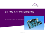
1. Configuration Diagram
Using RS-232C cable connected to the personal computer (Windows PC), flash memory data in the
microcontroller mounted in the user system can be reprogrammed. Note that the user system must
have an RS-232C driver for communication with the microcontroller UART.
1
2. Compatible Microcontrollers
FM0+:
S6E1A11B0A/C0A (*1), S6E1A12B0A/C0A (*1)
(*1: Added at V01L12)
FM3:
MB9AF102N/R, MB9AF104N/R
MB9AF111K, MB9AF112K
MB9AF111L/M/N, MB9AF112L/M/N, MB9AF114L/M/N, MB9AF115M/N, MB9AF116M/N
MB9AF121K/L
MB9AF131K/L, MB9AF132K/L
MB9AF131M/N, MB9AF132M/N
MB9AF141L/M/N, MB9AF142L/M/N, MB9AF144L/M/N
MB9AF154M/N/R, MB9AF155M/N/R, MB9AF156M/N/R
MB9AF1A1L/M/N(*2), MB9AF1A2L/M/N(*2)
MB9AF311K, MB9AF312K
MB9AF311L/M/N, MB9AF312L/M/N, MB9AF314L/M/N, MB9AF315M/N, MB9AF316M/N
MB9AF341L/M/N, MB9AF342L/M/N, MB9AF344L/M/N
MB9AF421K/L
MB9AFA31L/M/N, MB9AFA32L/M/N
MB9AFA41L/M/N, MB9AFA42L/M/N, MB9AFA44L/M/N
MB9AFAA1L/M/N(*2), MB9AFAA2L/M/N(*2)
MB9AFB41L/M/N, MB9AFB42L/M/N, MB9AFB44L/M/N
MB9BF104N/R, MB9BF105N/R, MB9BF106N/R
MB9BF112N/R, MB9BF114N/R, MB9BF115N/R, MB9BF116N/R
MB9BF116S/T, MB9BF117S/T, MB9BF118S/T
MB9BF121J
MB9BF121K/L/M, MB9BF122K/L/M, MB9BF124K/L/M
MB9BF128S/T, MB9BF129S/T
MB9BF216S/T, MB9BF217S/T, MB9BF218S/T
MB9BF304N/R, MB9BF305N/R, MB9BF306N/R
MB9BF312N/R, MB9BF314N/R, MB9BF315N/R, MB9BF316N/R
MB9BF316S/T, MB9BF317S/T, MB9BF318S/T
MB9BF321K/L/M, MB9BF322K/L/M, MB9BF324K/L/M
MB9BF328S/T, MB9BF329S/T
MB9BF404N/R, MB9BF405N/R, MB9BF406N/R
MB9BF412N/R, MB9BF414N/R, MB9BF415N/R, MB9BF416N/R
MB9BF416S/T, MB9BF417S/T, MB9BF418S/T
MB9BF428S/T, MB9BF429S/T
2
MB9BF500N/R, MB9BF504N/R, MB9BF505N/R, MB9BF506N/R
MB9BF512N/R, MB9BF514N/R, MB9BF515N/R, MB9BF516N/R
MB9BF516S/T, MB9BF517S/T, MB9BF518S/T
MB9BF521K/L/M, MB9BF522K/L/M, MB9BF524K/L/M
MB9BF528S/T, MB9BF529S/T
MB9BF616S/T, MB9BF617S/T, MB9BF618S/T
MB9BFD16S/T, MB9BFD17S/T, MB9BFD18S/T
(*1: Added at V01L14)
FM4:
MB9BF164K/L, MB9BF165K/L, MB9BF166K/L
MB9BF166M/N/R, MB9BF167M/N/R, MB9BF168M/N/R
MB9BF364K/L, MB9BF365K/L, MB9BF366K/L
MB9BF366M/N/R, MB9BF367M/N/R, MB9BF368M/N/R
MB9BF464K/L, MB9BF465K/L, MB9BF466K/L
MB9BF466M/N/R, MB9BF467M/N/R, MB9BF468M/N/R
MB9BF564K/L, MB9BF565K/L, MB9BF566K/L
MB9BF566M/N/R, MB9BF567M/N/R, MB9BF568M/N/R
Note: The MCU which has suffix (A, B, etc.) as end of Product Name (“MB…”),
and when it’s equivalent of the MCU which has no suffix, they are not in list.
3
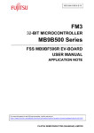
3. Example of Connection for On-board Programming
FM0+:
User system
VCC
10kΩ
X0
●
X1
●
●
Serial write:"1"
●
MD0
●
Device
INITX
RS-232C
Driver
10kΩ
●
P21/SIN_0
P22/SOT0_0
RS-232C
VSS
Note: The pull-up resistance values shown are for example.
Select the most appropriate resistance values for each system.
The MD0 pin cannot be controlled by the PC and should be set in the user system.
During serial reprogramming, when the INITX pin is set from “Low” to “High” level after setting the MD0
pin, the microcontroller enters the serial reprogramming mode, enabling serial reprogramming from the
PC.
After the reprogramming, control is shifted to the normally-used mode as for MD0 pin. Then INITX pin
set from “Low” to “High” level executes user program.
4
FM3, FM4:
*1
The MD1 and MD0 pins, and Pxx pins cannot be controlled by the PC and should be set in the user
system.
During serial reprogramming, when the INITX pin is set from “Low” to “High” level after setting the MD1
pin and MD0 pin, and Pxx pin, the microcontroller enters the serial reprogramming mode, enabling
serial reprogramming from the PC.
After the reprogramming, control is shifted to the normally-used mode as for MD1 and MD0 pins and to
the user circuit side as for Pxx pin. Then INITX pin set from “Low” to “High” level executes user
program.
*1 : The following MCU need not use P60 pin to select the serial programming mode.
[MCU] MB9AF13xK/L/M/N, MB9AFA3xL/M/N, MB9BF121J
5
4. Pins Used
(1) Pins used for serial programming
FM0+:
Supplement
Function
Pin name
Mode pin
MD0
Performing an external reset or turning on the power
after setting MD0=H enters the serial programming
mode.
Reset pin
INITX
-
UART serial data pin
P21/SIN0_0
Setting the input level of this pin to "H" until the start of
communication enables the UART programming mode.
UART serial data pin
P22/SOT0_0
-
FM3, FM4:
Function
Pin name
Mode pin
MD1, MD0
Communication mode
select pin
P60
*1
Supplement
Performing an external reset or turning on the power
after setting MD0=H and MD1=L enters the serial
programming mode.
Setting it to "L" enables the UART programming mode.
Reset pin
INITX
-
UART serial data pin
P21/SIN0_0
Setting the input level of this pin to "H" until the start of
communication enables the UART programming mode.
UART serial data pin
P22/SOT0_0
-
*1 : The following MCU need not use the P60 pin to select the serial communication mode.
[MCU] MB9AF13xK/L/M/N, MB9AFA3xL/M/N, MB9BF121J
6
5. Installation and Execution of Software
If there is the old version, uninstall it first before installation. Starting the installer to operate as
instructed will complete the installation. Note that the install might not be performed when a directory in
a deep nest is specified as the install directory.
And, if there is the software of an old version, the installer may perform only uninstallation of the old
version. Please start again the installer.
After installation, click the Windows Start button => Program => FLASH MCU Programmer => FM3 to
start the programmer software.
7
6. Programmer Functions
Erase, Blank Check, Program & Verify, Read & Compare, and Copy can be executed for flash memory
integrated into the microcontroller.
[LIMITATION]
When the flash security function is effective, please connect the external crystal oscillator.
If you use this program by the internal CR clock, for secured MCU, when you erase,
communication error will occur and the trimming data will disappear.
Main dialog box
Programmer software is started to open the dialog box as shown below.
Overview of operating procedure
First, complete setting of the user system (microcontroller board) that data is programmed to (see
Chapter 3). In starting or when setting has been changed, it is necessary to perform downloading
(described later).
After downloading terminates normally, perform procedures such as Erase and Programming.
8
6-1. Downloading
This section describes the operating procedure for downloading and the operating state of the
program.
(1) Specify the type of microcontroller used in the user system in Target Microcontroller of the main
dialog box.
(2) Specify the frequency of the crystal oscillator input to the microcontroller in Crystal Frequency of
the main dialog box.
The frequency of the crystal oscillator that can be specified for each type of microcontroller is
limited. Please see [6-1-1. Frequency List].
(3) Select the COM port of the PC connected to the user system.
Click the [Set Environment] button in the main dialog box to open the setup window. When the
[COM PORT] tab in the setup window is clicked, the specifying window is opened.
(4) Execution of downloading
Click the [Download] button.
If the following dialog window is opened, Input a reset signal to the microcontroller to start the
program in the flash programming mode and then click the [OK] button
Downloading is performed to open the “Download” window. When downloading is completed
normally, the following dialog window opens.
When the [OK] button is clicked to close the dialog window, the [Erase], [Blank Check], [Program &
Verify], [Read & Compare] and [Copy] buttons are enabled.
9
6-1-1. Frequency List
Notice:
This program will not operate normally if the microcontroller uses a crystal oscillator
frequency not listed in the table. Don’t connect a crystal oscillator with the main clock pin of
target microcontroller when the "CR clock" is selected.
FM0+:
Target Microcontroller
Crystal Frequency (MHz)
S6E1A11B0A / S6E1A11C0A,
S6E1A12B0A / S6E1A12C0A
CR Clock, 4,8,16,24
Target Microcontroller
Crystal Frequency (MHz)
MB9AF10xN/R
4,8,16,24
MB9AF11xM/N, MB9AF11xL/M/N,
MB9AF31xM/N, MB9AF31xL/M/N
4,8,16,24
MB9AF11xK, MB9AF31xK
CR Clock, 4,8,16,24
MB9AF121K/L, MB9AF421K/L
CR Clock, 4,8,16,24
MB9AF13xK/L
CR Clock, 4,8,16
FM3:
MB9AF13xM/N, MB9AFA3xL/M/N,
MB9AF1AxL/M/N, MB9AFAAxL/M/N
MB9AF14xL/M/N, MB9AF34xL/M/N,
MB9AFA4xL/M/N, MB9AFB4xL/M/N
CR Clock, 4,8,16
CR Clock, 4,8,16,24
MB9AF15xM/N/R
CR Clock, 4,8,16,24
MB9BF10xN/R, MB9BF30xN/R,
MB9BF40xN/R, MB9BF50xN/R
4,8,16,24,48
MB9BF11xN/R, MB9BF31xN/R,
MB9BF41xN/R, MB9BF51xN/R
4,8,16,24,48
MB9BF11xS/T, MB9BF21xS/T, MB9BF31xS/T,
MB9BF41xS/T, MB9BF51xS/T, MB9BF61xS/T,
MB9BFD1xS/T
4,8,16,24,48
MB9BF12xK/L/M, MB9BF32xK/L/M,
MB9BF52xK/L/M
CR Clock, 4,8,16,24
MB9BF12xS/T, MB9BF32xS/T,
MB9BF42xS/T, MB9BF52xS/T
CR Clock, 4,8,16,24
MB9BF121J
CR Clock, 4,8,16,24
Target Microcontroller
Crystal Frequency (MHz)
MB9BF16xK/L, MB9BF36xK/L,
MB9BF46xK/L, MB9BF56xK/L
CR Clock, 4,8,16,24,48
MB9BF16xM/N/R, MB9BF36xM/N/R,
MB9BF46xM/N/R, MB9BF56xM/N/R
CR Clock, 4,8,16,24,48
FM4:
10
6-2. Erasing and Programming
This section explains how to specify Hex File and the processing and operation performed when the
[Erase], [Blank Check], [Program & Verify], [Read & Compare], [Copy] and [Full Operation (D+E+B+P)]
buttons are clicked.
[LIMITATION]
When the flash security function is effective, please connect the external crystal oscillator.
If you use this program by the internal CR clock, for secured MCU, when you erase,
communication error will occur and the trimming data will disappear.
11
(a) Hex File: Select the file to be programmed to flash memory
Specify the Motorola-S or Intel-HEX format file to be programmed to flash memory in the
microcontroller.
Although the specification method by drags and drops a direct file from
Explorer etc. is recommended, it can specify also by the file appointed window displayed by
pushing the [Open] button.
Hex File must be specified to execute [Program & Verify], [Read & Compare] and [Full Operation
(D+E+B+P)]. Since it is decoded at the head of these processings each time, even if the
specified Motorola-S or Intel-HEX format file changes specification of a file just before
processing, it is OK.
After Hex File is specified, checksum to ROM image after Motorola-S format file or Intel-HEX
format file shown in Hex File is deciphering done can be calculated.
The dialog box to calculate checksum when a lower right [Check SUM] button is pushed opens.
The range of the calculation of checksum is limited to the Flash area shown in the upper right of
the main dialog. When the area has divided into plural block, the empty area between blocks is
not added, and the total of each block is calculated.
The calculation method is simple addition of every one byte, and the result shows the last 4
digits (It is not a complement representation) by the hexadecimal number.
ROM value in the Flash area not shown in Hex File is calculated assuming that it is a value
indicated by Fill Data at the left of the dialog. When starting, FF is set here. Please specify it by
two hexadecimal number digits when changing.
[Notes concerning checksum]
This function doesn't calculate the checksum of ROM image written in the FLASH memory in the
microcontroller chip. When Hex File is not specified, and the error is detected at the
decipherment of Hex File, nothing is displayed.
The SUM value calculated here is not peculiar against Hex File. When another microcontroller is
selected, same Hex File might reach another value.
The value specified with Fill Data is not written at the time of writing. This value is used only for
the calculation of checksum.
12
(b) Erase: Erase all flash memory areas
All flash memory must be in the blank state (0xff) when programming a new program to it. By
pushing this button, a chip erase command is published to FLASH and elimination is performed.
When the flash memory is protected, the following windows might be displayed while executing
the Erase command. If the following dialog window is opened, Input a reset signal to the
microcontroller to start the program in the flash programming mode and then click the [OK]
button.
In addition, a blank check does not perform this command.
(c) Blank Check: Check that all flash memory areas are blank
This button is clicked to check that all flash memory is in the blank state (0xff).
(d) Program & Verify: Program data to flash memory
This button is clicked to program the Motorola-S or Intel-HEX format file specified in Hex File to
flash memory in the microcontroller concurrently with verification. An error dialog is displayed,
when writing is performed for 512 bytes of every block and a CRC error is detected by the block.
This dialog If YES is pushed, the block of an error will be resent and it will continue writing. A push on
NO interrupts write-in processing.
13
(e) Read & Compare: Compare Hex File with data in flash memory in microcontroller
This button is clicked to compare data in the Motorola-S or Intel-HEX format file specified in Hex
File with data in flash memory in the microcontroller.
Like the [Program & Verify] processing, The
data of FLASH is transmitted for 512 bytes of every block, a CRC error check is performed, and
comparison processing is performed.
(f) Copy: Save data in flash memory in microcontroller to file
This button is clicked to read data from flash memory integrated into the microcontroller and save
it as an Motorola-S or Intel-HEX format file. Like [Read & Compare] processing, FLASH memory
reading is performed for 512 bytes of every block, and a CRC error check is performed similarly.
The output file format can be changed by right-clicking in the Copy button. The button name
changes by [Copy] and [Copy_i] whenever right-clicking. The state of [Copy] shows Motorola-S
format, and the state of [Copy_i] shows Intel-HEX format.
Processing begins when the button is left-clicked, the folder is specified preservation ahead, the
file name is input, and the [Save] button is pushed when the form is selected.
(g) Full Operation (D+E+B+P): Automatic programming
Operation to [Download] to [Program & Verify] is performed by package.
In the case of a blank chip, processing is performed in order of [Download], [Blankcheck], and
[Program & Verify]. When it is not a blank chip, processing is performed in order of [Download],
[Blankcheck], [Erase], [Blankcheck], and [Program & Verify].
14
6-3. Motorola-S format decoder specification
Before programming, Motorola-S format Decoder of programmer changes Motorola S format data into
binary data, according to the following specification.
(a) The decoder does not error when overlap of addresses occurs.
The decoder does not error about overlap of address. If user writes a data on an address which was
already written another data before, former data is overwritten by new data.
(b) Available address
If user writes a data beyond an address range of FLASH memory, programming results in an error.
(c) About the error detected by the decoder.
The error detected by the decoder is the following (1)-(4). When these errors are detected,
processing is interrupted by the decoder. Then the line number and the cause of the error are
displayed in the dialog window.
(1) file error
The start of the line is not "S".
(2) S-format error
The start of the line is not "S0","S1","S2","S3","S5","S7","S8" and "S9".
(3) decode error
・There are character except "0123456789ABCDEF".("S" is excluded. See (1) and (2).) And, the
small letter "abcdef" cannot be used.
・The LENGTH data is different from the length of an actual data row.
・The SUM data is different.
(4) address error
There is data besides the FLASH area. (See b.Available address)
(d) Other detail
The decoder skips a line. even if the line is contained only new-line code NL and programming goes
on.
A line beginning with "S0","S5","S7","S8" and "S9" is ignored and decoder skips such lines in S
format file without error.
15
6-4. Intel-Hex format decoder specification
Before programming, Intel-Hex format Decoder of programmer changes Intel-Hex format data into
binary data, according to the following specification.
(a) The decoder does not error when overlap of addresses occurs.
The decoder does not error about overlap of address. If user writes a data on an address which was
already written another data before, former data is overwritten by new data.
(b) Available address
If user writes a data beyond an address range of FLASH memory, programming results in an error.
(c) About the error detected by the decoder.
The error detected by the decoder is the following (1)-(4). When these errors are detected,
processing is interrupted by the decoder. Then the line number and the cause of the error are
displayed in the dialog window.
(1) file error
The start of the line is not ":".
(2) decode error
There are character except "0123456789ABCDEF".(":" is excluded. See (1).) And, the small letter
"abcdef" cannot be used.
The record type is not 00, 01, 02, 03, 04, and 05.
The length of the data string that turns out by the number of data is different from the length of an
actual data string.
The SUM data is different.
(3) record error
When not is in number 0 of data at 01 records.
When not is in number 2 of data at 02 records.
When not is in number 4 of data at 03 records.
When not is in number 2 of data at 04 records.
When not is in number 4 of data at 05 records.
(4) address error
There is data besides the FLASH area. (See b.Available address)
16
7. Operating environment
Required equipment :
- Windows PC with the RS-232C port
- RS-232C cable (commercial item)
OS :
- Windows XP / Windows Vista / Windows 7
* There is fault that some characters are not displayed correctly, in Windows Vista. However, we are
checking that the program is performing normal operation.
Memory size :
- More than the memory quantity that OS recommends
Hard disk :
- (Availability) Not less than 10 MB
NOTICE : The operations of all models that meet the above conditions may not be ensured.
17
8. Others
(A) Setting of voice output
The setting of voice generated when an error occurs and processing is terminated normally can be
changed.
Select the [Sound] tab in the setup window that opens when the [Set Environment] button is clicked.
To output sound, put a check in the Enable sound checkbox.
Check the status of sound output. Select ERROR or END in the sound column.
Select Wave or Beep as the type of sound to be output in Sound type.
Set the voice file to be output in the Wave file column only when Wave is selected. When the
[Open] button is clicked, the File Open window is opened. Select the Wave file to be output. The
[Play] button is used to play the set Wave file. The [Stop] button is used to stop the Wave file.
(B) Setting of tooltips display
The tooltips display can be “enabled” or “disabled”.
Select the [Tooltips] tab in the setup window that opens when the [Set Environment] button is clicked.
When a checkmark is put in the tooltips checkbox to move the mouse cursor over the contents such
as buttons in the dialog window, simple help (the full path of a file for Hex File) is displayed.
18
(C) Error messages
Many error messages are displayed owing to the setting mistake of hardware and software.
the case where an error is outputted in addition even if it checks these in detail, please tell the
person in charge of software acquisition origin a detailed condition.
No.
Item
No.001 Message
Description
Download error *1
Cause
The response of download processing is unusual.
Action
Please check connection and a setup of hardware.
No.003 Message
Timeout error
Cause
The response of a command does not come on the contrary.
Action
Please check connection and a setup of hardware.
No.006 Message
Unable to open COM port
Cause
Another application is using COM.
Action
Please check the use situation and port number of a COM port.
No.007 Message
Unable to open Download file
Cause
m_flash.xxx not found
Action
Please reinstall this software.
No.009 Message
Unable to gain COM port info
Cause
It will be in the state where the target COM port can be used.
Action
Please check the number of a COM port and setup to be used.
No.010 Message
Unable to change COM port setting
Cause
A communication setup cannot be set as the target COM port.
Action
Please inform support of condition.
No.011 Message
Communication error
Cause
The unusual command response was received.
Action
Please reperform by improving connection and a setup of hardware.
No.012 Message
Read error
Cause
The response at the time of read&compare or copy processing is unusual.
Action
Please reperform by improving connection and a setup of hardware.
No.013 Message
Program error
Cause
The response at the time of Program&Verify processing is unusual.
Action
Please reperform by checking whether a chip is blank.
No.015 Message
COM port write error
Cause
There is the possibility of the abnormalities of a COM port driver or the port
itself.
Action
Please inform support of condition.
19
No.
No.016
No.017
No.018
No.019
No.101
No.105
No.106
No.107
No.207
*2
*1:
Item
Description
Message
COM port read error
Cause
There is the possibility of the abnormalities of a COM port driver or the port
itself.
Action
Please inform support of condition.
Message
File access error
Cause
Access of a m_flash.xxx file went wrong.
Action
Return the folder and file configurations to the installation defaults.
Message
Erase error *1
Cause
The response at the time of erase processing is unusual. There is the
possibility that a chip is poor.
Action
Please improve a setup of hardware or exchange chips.
Message
Unable to open KEY file
Cause
Key file can not open.
Action
Please create and set up right key file.
Message
Please set "hex file"
Cause
“Hex file” not set
Action
Set “hex file” in the dialog box.
Message
key length too short
Cause
The minimum conditions for key length are not met.
Action
Prepare a correct security file.
Message
key length too long
Cause
The maximum conditions for key length are not met.
Action
Prepare a correct security file.
Message
Illegal security file
Cause
The security file description is invalid.
Action
Prepare a correct security file.
Message
memory is not available
Cause
Unable to allocate memory for execution
Action
Quit any running application and retry.
Message
Please redo from download operation.
“MCU xxH” is displayed if the error cause is returned from the microcontroller at a download error.
“MCU xxH” means:
MCU 02H SUM error at downloading
MCU 04H Abnormal termination at downloading
*2:
This is an additional message.
It is displayed as necessary after other messages are displayed.
20
9. Cautions
The PC programming software has the possibility of receiving the influence by the communications
cable, the outside environment, and the PC.
Therefore, please evaluate it enough when you use the software.
Please use programming systems of programmer venders when you write two or more devices at the
same time.
The specifications of the product are subject to change without notice.
21