1
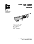
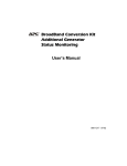
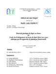
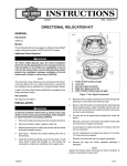
The MELLEN Company, Inc.

www.MELLENCompany.com
MTSCR Furnace
MA# 100092
Congratulations on your purchase of a MELLEN Furnace. In order to assist in
your scientific procedures, please consult this manual prior to unpacking and installation.
Please contact technical support at the MELLEN Company:
40 Chenell Drive
Concord, NH 03301
phone 603-228-2929
Fax 603-228-5727
E-mail [email protected] with additional questions.
1
Contents
Contact Information…………………………………….1
Furnace Information…………………………………….3
Safety Information………………………………………3
Unpacking Instructions…………………………………4
Initial Run/Bake-Out Instructions………………………5-7
Basic Operation…………………………………………7
Thermocouples Installation…....………………..……..8
Element Replacement..................…………………….9-11
Thermocouple INFO...................................................12
Wiring INFO................................................................12
Troubleshooting Guide………………………………….13
Safety Data Sheets are attached to printed copies from MELLEN
Diagrams, Spare Parts List, etc are in the back pocket of hard copies from MELLEN

Furnace Information
All MELLEN furnaces are labeled with an information sticker allowing the user to access necessary information concerning the furnace.
The serial number for the MELLEN Furnace is located on a MELLEN furnace plate
primarily located on the cage on the furnace. Attached to this plate, you will conveniently find the Furnace Model Number, Serial Number as well as contact data for
the MELLEN Company.
The furnace plate also contains wattage and voltage information, zone configuration
and any special adaptations on this furnace.
Important Safety Information
• Never place any part of the body in the furnace or touch the furnace while activated or while cooling.
• Use proper ventilation at all times, do not inhale fumes from a bake-out procedure or a run. Do not approach the furnace without a mask.
• Never have food or drink near the furnace.
• Apply proper voltage to the heaters.
• Provide at least ½” clearance between furnace surface and any conductive parts.
• Take necessary precautions when handling high temperature materials.
• Do NOT exceed the recommended temperature ratings.
• Do not modify or drill holes to the heaters without consulting MELLEN (603-2282929).
• Do NOT support the furnace by any electrical parts.
• Do NOT bury any electrical interconnections between the furnace and any equipment.
• Furnace should be level and free from vibrations.
• Furnace should be installed and grounded in accordance with national and local
codes.
• Avoid contact between furnace and any metallic object.
• Always wash hands after coming in contact with furnace and components.
• Do not place any combustible components inside the furnace.
• Do not hold furnace by the knobs used to open and close the furnace.
page 3
Unpacking Instructions
Remove furnace from box or crate.
Inspect furnace for any damage.
Report any damage to the delivering carrier immediately to insure a
proper claim.
Remove any packaging material from the bore, paying attention not
to damage the insulation.
Do not drop box or furnace.
page 4
Initial Run and Bake-Out Instructions
Please follow the appropriate Bake-Out Instructions, either Single Zone BakeOut Procedure (for furnaces with one heating zone) or Bake-Out Procedure for
Multiple Zone Furnaces (for furnaces with more than one heating zone).
The furnace contains carefully selected insulation to permit the best possible
operation. This insulation inherently contains moisture that must be slowly and
completely removed before the furnace can be fully utilized. During this drying
period, a small quantity of smoke and vapors from the binders in the embedding
cement will also be emitted. The smoke will have a bad odor, so provide adequate ventilation.
Please inspect the furnace prior to the bake-out procedure. Please be sure that
the furnace core is empty, that nothing is inside of it (ie. no papers, office supplies, tools etc). Please be sure that nothing is on the exterior of the furnace as
well. Remove plastic protective wrap adhering to furnace skins. This protective
layer is intended for shipping purposes only and must be removed prior to operation.
Please follow the recommended procedure(s) to properly dry out the furnace
insulation for maximum operating success. ……………………….
Single Zone Bake-Out Procedure
1. If your furnace is a horizontal furnace, please raise one end to up to 30 degrees and not less than 5 degrees. If you can not raise one end of the furnace, contact MELLEN to verify that it is OK to run the bakeout in its fixed
position.
2. At the furnace ends, place the furnace plugs slightly inserted, in order for furnace to reach required temperature. Be sure to leave a gap, an opening for
the smoke to escape during bake-out.
3. Vent the smoke outside through the use of a hood or exhaust collector.
4. Make certain that the bore is empty.
5. Check the furnace power leads for possible shorts.
6. Raise the temperature of the furnace to 800° in three steps:
STEP A 200° C for one hour
STEP B 400°C for two hours
STEP C 800° C for one hour
The furnace may now be cooled down and is ready for use.
Multiple Zone Bake-Out Procedure
1. If your furnace is a horizontal furnace, please raise one end to up to 30 degrees and not less than 5 degrees. If you can not raise one end of the furnace, contact MELLEN to verify that it is OK to run the bakeout in its fixed
position.
2. At the furnace ends, place the furnace plugs slightly inserted, in order for
furnace to reach required temperature. Be sure to leave a gap, an opening
for the smoke to escape during bake-out.
3. Vent the smoke outside through the use of a hood or exhaust collector.
4. Make certain that the bore is empty.
5. Check the furnace power leads for possible shorts.
6. On the first firing, the power should be applied to every other zone, never
to two adjoining zones at the same time. It is recommended that in a three
zone furnace, that the middle zone (zone 2) be fired or baked-out first.
Then, upon completion of zone 2 bake out procedure, that zones 1 and 3
can be baked out together.
7. Raise the temperature of the zones being fired to a minimum of 1000° C in
four steps
200° C for one hour
400°C for one hour
800°C for one hour
1000°C for one hour
After this bake-out has been completed, turn off the zones. The remaining
zones may now be baked-out following the same procedure, (zones 1 and 3).
It is recommended that this procedure be done in succession, that is baking out
the remaining zones, before the furnace cools. In the case that this is achieved,
skip to step 3, 800°C for 1 hour, and begin baking zones 1 and 3 at this step.
Then, continue as normal and bake at 1000° C for 1 hour. The bake-out is now
complete.
After the initial drying out run, the furnace should be run approximately 10°C
- 40°C above the normal operating temperature, without exceeding the rated
temperature, to fully stabilize the furnace. Under no circumstances should the
rated temperature of the furnace be exceeded.
WARNING: Multi-zone furnaces – SERIOUS DAMAGE may result if steps
6-7 are not followed when baking out multi-zone furnaces.
WARNING: Due to the possibility of combustible gases being given off by the
refractory cement binders as the furnace is heated, Mellen recommends operating the furnace in a tilted or vertical position prevent local hot spots an possible
damage to the heating elements or element. Both ends of the bore should be
open (or slightly ajar with furnace plugs) and the bore empty. After the initial run,
the furnace can be operated normally.
Basic Operation
The furnace should be brought to temperature as slowly as is practical for your
applications. During prolonged periods of inactivity, the furnace should be shut
off or idled at approximately 1000° F (538°C).
The furnace should be level and free from vibrations.
Check the furnace for shorts from inputs to ground. Check the resistance of the
heating element(s) to see that the connections are tight and free of oxides. The
resistance should be checked across the two end terminals
Although the furnace has a nominal rating, the furnace should never be connected to a line without an automatic or manual voltage control in front of it.
CAUTION:
The furnace, transformer (if required), and control cabinet should be installed
and grounded in accordance with National and local codes.
Multi-Zone Furnaces are supplied with one grounding wire and two power leads
for each zone.
page 7
Thermocouple Installation
mocouple in place.
The furnace can use various thermocouples depending on
application - type K, S or R. The thermocouple or TC is inserted in the backside of the furnace in the TC holder.
Insert the thermocouple carefully, as thermocouples are
fragile.
Loosen the bolt on the top of the TC and hold the washer to
the top of the bolt away from the TC holder.
Slide the thermocouple into the furnace, keeping the washer
outside the holder.
Using a screwdriver, gently tighten the bolt to hold the ther-
The thermocouple slides into the furnace
and just barely protrudes from the inside of
the furnace.
page 8
Element Replacement
Tools Required:
1/8” Allen wrench
replacement element(s)
needle nose pliers
Wire cutters
Be certain that furnace and elements are
completely cool and at room temperature
before replacing any MELLEN elements.
Wear a protective mask when handling
elements.
To replace the BOTTOM element:
1. Remove the screw using the Allen
wrench located on the side of the furnace as shown in the photo above.
2. Gently slide out the insulation on
the side of the element as shown in
the photos on the right.
Gently set aside.
3. Using the needle nose pliers, slide
the metal clip sideways holding the
element in place.
4. Remove all 4 clips following the same procedure and set clips aside.
5.Gently close the furnace.
6. Remove two screws holding the perforated
screen onto the furnace. Set screws aside.
7. Cut the wire connections on the leads of
the element.
8.Slide out element. Set aside.
Replace new element in the furnace with
the leads inserted through to the back of the
furnace.
1. Slide an element clip between the element
and the insulation.
2. Repeat with three remaining clips.
3. Replace insulation on the side of the furnace
between element and furnace skin.
4. Replace screw on the side of the furnace.
5.Gently close the furnace.
5. Attach leads in the back of the furnace by crimping with a buttsplice to the wire.
6.Replace perforated cage on the back of the furnace.
To Replace the element on the TOP of the furnace, follow
the same procedure for replacing the bottom element, but
remove the cage on the top of the furnace. Remove the
two screws on the top of the furnace to remove the cage.
Clip the wires as shown before removing element clips and
insulation.
Open the furnace and remove insulation, then element
clips, then slide out
element.
To replace element,
slide element leads
through the furnace
and replace clips and insulation then attach
the leads.
page 11
Thermocouple Care
TC’s should be handled with care. The ceramics are fragile and thus can be
broken easily. A broken ceramic can lead to broken or twisted wires which
may cause a second junction to be formed resulting in incorrect temperature
readings.
Exposing the TC to arsenic or any other corrosive material may contaminate
the TC. The TC should be cleaned or replaced if the TC appears to be corroded or attacked in any way.
Thermocouples wear out through normal use and should be replaced as
needed. Thermocouples placed inside the furnace improperly will most likely
be damaged and need to be replaced sooner than expected.
WIRING
See accompanying wiring control diagram included in the rear pocket of this manual (if applicable).
Connect the required line voltage to the controller
Connect the thermocouple extension wire between the controller and
the furnace. Each TC, labeled Zone 1, Zone 2, Zone 3, etc connects
to the corresponding TC wire, which in turn connects to the corresponding labeled zone in the power supply. (Be certain that zone 1
corresponds to TC zone 1 etc). In order to connect the TC wire to
the TC, gently, but firmly grasp the TC and carefully connect the TC
prongs to the plug of the wire. The connection will be flush when
fully connected.
Connect the controller power-out to the furnace or immediate transfer input, whichever is applicable (see wiring diagram).
Be sure that the furnace and controller are properly grounded.
Observe local and National Codes for wiring and electrical.
page 12
Controller Overview
The controller is set up at MELLEN and the instruments are ready to operate
upon set up. If you wish to change the set setpoint please follow these procedures.
Further instruction is included in the OMEGA controller manual.
To turn the unit on, switch the white ON/OFF switch as illustrated in the photo
above.
To change the setpoint on the controller, use the instrument on the left hand side.
Press and hold the star button (far left) and while holding it down, press the up or
down arrow keys to change the setpoint.
To shut the unit off, simply shut the ON/OFF switch.
Over-Temperature Controller
The Over-temperature (OT) setpoint is set at the
maximum temperature for your unit. MELLEN
recommends setting this no more than 100o
over the operating temperature of your furnace,
NEVER to exceed the maximum operating
temperature of the furnace.
If you wish to change the OT setpoint, follow
these instructions:
1. Press the UP arrow & the SETUP key at the
same time.
2. Use the ▲ or ▼ to scroll through 4 choices
on the screen (OPTR, SETP, CONF, INFO).
Stop scrolling when you see SETP.
3. Press the SETUP key. ULOC will show up on the screen.
4. Using the ▲ and ▼ keys, press until the number 10 appears onscreen. This
is the unlock code.
5. Once you have the number 10 onscreen, press the SETUP key and the SETPOINT will be displayed.
6. Using the ▲ and ▼ keys, choose your new setpoint.
7. Once you have your desired number onscreen, press RESET.
8. Press the SETUP key to scroll to the next screen.
9. Press SETUP & ▲ at the same time to return to the main menu.
10. Select OPTR by scrolling with the ▲key.
11. Press SETUP and you will now be in operator mode (OPTR) and the new
setpoint will be active.
page 14

Troubleshooting Guide
LED Display doesn’t light up –
Check to make sure unit is plugged in. Check power connections.
FURNACE DOESN’T HEAT –
Heating element burned out.
SCR burned out.
Call MELLEN for technical support
(603 228-2929) [email protected]
FURNACE EMITS SMOKE after bake-outShut unit off.
Check for combustible substances inside furnace bore.
Determine if smoke is coming from controller or furnace bore. If coming from
controller, call MELLEN technical support immediately.
TC NEEDS REPLACEMENT –
Call MELLEN (603 228-2929)
ELEMENTS NEED REPLACEMENT
Call Mellen (603 228-2929)
page 15