1
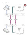
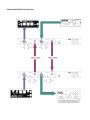
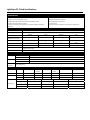
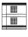
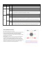
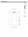
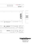
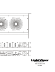
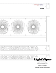
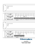
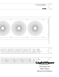
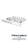
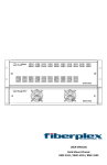
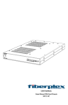
USER MANUAL FOR EF‐2 Physical Layer Ethernet Fiber Optic Converter Warning for Your Protection 1. Read these instructions 2. Keep these instructions 3. Heed all warnings 4. Follow all instructions 5. Do not use this apparatus near water. 6. Clean only with a dry cloth. 7. Do not block any of the ventilation openings. Install in accordance with the manufacturer’s instructions. 8. Do not install near any heat sources such as radiators, heat registers, stoves, or other apparatus (including amplifiers) that produce heat. 9. Do not defeat the safety purpose of the polarized or grounding‐type plug. A polarized plug has two blades with one wider than the other. A grounding type plug has two blades and a third grounding prong. The wide blade or the third prong are provided for your safety. If the provided plug does not fit into your outlet, consult an electrician for replacement of the obsolete outlet. 10. Protect the power cord from being walked on or pinched, particularly at plugs, convenience receptacles, and the point where they exit from the apparatus. 11. Only use attachments/accessories specified by the manufacturer. 12. Use only with the cart, stand, tripod, bracket, or table specified by the manufacturer, or sold with the apparatus. tip‐over. When a cart is used, use caution when moving the cart/apparatus combination to avoid injury from 13. Unplug this apparatus during lightning storms or when unused for long periods of time. 14. Refer all servicing to qualified service personnel. Servicing is required when the apparatus has been damaged fallen into the in any way, such as power‐supply cord or plug is damaged, liquid has been spilled or objects have apparatus, the apparatus has been exposed to rain or moisture, does not operate normally, or has been dropped. The apparatus shall not be exposed to dripping or splashing. No objects filled with liquids, such as vases, shall be placed on the apparatus. “WARNING To reduce the risk of fire or electric shock, do not expose this apparatus to rain or moisture.” 1 Registration Be sure to register your LightViper product, either by filling in the enclosed Registration Card or by completing the on‐line registration form at our Web site: http://lightviper.com/register If you do so, FiberPlex can contact you with any update information. As enhancements and upgrades are developed, you will be contacted at the registration address. Please read this manual ‐ if you call for technical support, we’ll assume that you have. Please address any inquiries to your dealer or directly to FiberPlex at: FiberPlex Inc. 10840‐412 Guilford Rd. Annapolis Junction, MD 20701 301.604.0100 Fax: 301.604.0773 [email protected] Warranty, Service and Terms and Conditions of Sale For information about Warranty or Service information, please see our published ‘Terms and Conditions of Sale’. This document is available on fiberplex.com or can be obtained by requesting it from [email protected] or calling 301.604.0100. Disposal Disposal of Packing Materials The packing materials have been selected with environmental and disposal issues in mind. All packing material can be recycled. Recycling packing saves raw materials and reduces the volume of waste. If you need to dispose of the transport packing materials, please try to use recyclable means. Disposal of Used Equipment Used equipment contains valuable raw materials as well as materials that must be disposed of professionally. Please return your used equipment via an authorized specialist dealer or via the public waste disposal system, ensuring any material that can be recycled is. Please take care that your used equipment cannot be abused. After having disconnected your used equipment from the mains supply, make sure that the mains connector and the mains cable are made useless. Declarations of Conformity Class A Equipment ‐ FCC Notice This equipment has been tested and found to comply with the limits for a Class A digital device, pursuant to Part 15 of the FCC Rules. These limits are designed to provide a reasonable protection against harmful interference when the equipment is operated in a commercial environment. This equipment generates, uses, and can radiate radio frequency energy and, if not installed and used in accordance with the instruction manual, may cause harmful interference to radio communications. Operation of this equipment in a residential area is likely to cause harmful interference, in which case the user will be required to correct the interference at their own expense. Disclaimer The information in this document has been carefully checked and is believed to be accurate at the time of publication. However, no responsibility is taken by us for inaccuracies, errors, or omissions, nor is any liability assumed for any loss or damage resulting either directly or indirectly from use of the information contained within it. 3 Introduction Congratulations on your purchase of a LightViper system. LightViper products are designed, engineered and manufactured by FiberPlex Inc., experts in fiber optics with decades of experience. Our work in audio and data communications products is known in US government applications worldwide. LightViper products combine our fiber optic technology with the highest standards in audio engineering. The EF‐2 You have purchased the LightViper EF‐2 system, 2 channel Physical Ethernet Fiber Optic Transport System (FTS) that has ability to pass standard 10 Base‐T and 100 Base‐T Ethernet communications as well as many proprietary Physical Ethernet based data such as those made by AVIOM™. The Fiber Advantage Fiber optics offer many advantages over copper: Transmits light rather than electrons Transmission over greater distances (more than 2 Km [1.25 mile]) Complete electrical isolation Immunity to RFI and EMI Eliminates ground loop problems Can be routed overhead, through walls, or underground Avoids foot traffic while maintaining aesthetics Functional Considerations The Light Viper EF‐2 is a very simple device. It is designed to be completely transparent to the data. A single EF‐2 actually contains 2 completely isolated and independent channels of Physical Ethernet. Each channels configuration is completely separate from the other. To be completely transparent to the data requires some initial switch settings to achieve the desired result. These settings are described in the later part of this document. Standard Components In its standard configuration, the Light Viper EF‐2 is made up of three primary components. 2 ea. Ethernet Transport device (EF‐2) — This is the hardware interface. One unit is placed on each end of the fiber connection. Each EF‐2 can handle two independent Physical Ethernet channels on up to 4 fibers. The Fiber Cable (TFC‐0000‐04) — The lightweight “tactical grade” fiber ‘cable’ that carries the digital signal between the stage and mixer boxes. Either PVC or Plenum rated fiber is recommended (VFC‐0000‐D, VFC‐0000‐DP) for installation use. Additionally an EF‐2 configuration can use the following component: TAC‐4 Connector Panels (VPL‐11, VPL‐12, VPL‐13) – These 1U rack panels contain (1), (2), or (3) panel mount TAC‐4 connectors mounted respectively and allow connection between tactical grade fiber to the ST connectors on the EF‐2 units. Getting Started Setup Setting up, and using your Light Viper EF‐2 is a quick and simple process. Just follow these steps: 1. Mount one EF‐2 in a rack close to the Ethernet source. 2. Mount the other EF‐2 in a rack close to the Ethernet destination. 3. Connect the units to either AC power using the IEC connector or 12VDC using the green modular connector. 4. Connect and run the Fiber between the two units, power up and check the ‘link’ light on both units 5. Set the switches for the appropriate signal. 6. Connect the data connections to the RJ‐45 jacks. The specific functions of the Light Viper EF‐2 (direction, polarity, etc.) are addressed within this manual. 5 Indicators and Controls 1 2 3 4 5 6 7 8 9 1 Data connection The data connection to the EF‐2 is made via a Neutrik™ Ethercon RJ‐45 connector. It uses a standard Ethernet pinout which is configured using the Polarity Switch. See appendix for a detailed pinout. 2 Data Status LEDs A Yellow indication on the upper LED marked “TP RX” indicates that receive data is being detected on the twisted pair. The lower LED indicates the Link status on the twisted pair. See appendix for more detail. 3 Polarity Switch Setting this switch to or sets the pinout of TX and RX to accommodate connection to various devices. With a setting of “Auto”, the EF‐2 will determine the correct pinouts for the TX and RX. See the appendix for more detail. 4 Directional Mode Switch The OPT RX and OPT TX positions are both unidirectional modes. In the OPT RX position, data is received by the fiber optic input and transmitted out to the RJ‐45 connector. In the OPT TX position data is received by the RJ‐45 connector and transmitted to the fiber optic output. The TX/RX position is a bidirectional mode which acts as a standard Ethernet connection. See the appendix for more detail. 5 Fiber Connections The EF‐2 comes standard with LC fiber connectors. ST, tactical grade TAC‐4 connectors, or Neutrik™ OpticalCon connectors are available as options. In live production use, it is recommended to fit the units with LC connectors and utilize the VPL‐11, 12, or 13 panels containing 1, 2, or 3, TAC‐4 panel mount connectors respectively. TAC‐4JR –LC connectors have LC pigtails which connect with the LC connectors on the EF2. Alternately the TAC‐4FR connector can be mounted directly on the chassis of the EF2. Always be sure to use appropriate fiber and compatible connectors. 6 Fiber Status LEDs A Yellow indication on the upper LED marked “OPT RX” indicates that receive data is being detected on the fiber connection. The lower LED indicates the Link status on the fiber connection. See appendix for more detail. 7 Power LED A green LED indicates the power supply is operating correctly. 8 DC Power Connector The EF‐2 can run on 9‐24VDC connected via this connector. 9 AC Power Connector The EF‐2 runs on a full range switching power supply. It will accept voltages from 90‐250 VAC. This connector also serves as a fuse holder. Replace fuse only with a 1 Amp 250V (T1AL250V) slo‐blo fuse. Using the Light Viper EF‐2 Standard Ethernet connection 7 Standard AVIOM PRO‐16 connection Fiber Options Tactical grade military fiber (TAC‐4) Used for live production applications (P/N TFC‐0000‐04). Weighing 8.4 lbs.(12.6kg) for(300)feet, this cable contains (4) fibers and therefore it is capable of carrying the signals of (2) systems on a single cable. The TAC‐4 connectors are hermaphroditic and can be connected to one another. Multimode fiber can transport signals up to 2km (1.25 miles). TAC-4 Neutrik OpticalCon® Fiber This fiber cable contains (2) fibers and is also a tactical grade fiber (P/N TFC‐0000‐02OC). Neutrik OpticalCon Fiber Cable & Panel Mount Connector PVC fiber PVC duplex fiber contains (2) fibers. Plenum rated fiber is also available. The installer can terminate the fiber themselves, or Fiberplex can supply it pre‐terminated. This fiber is also available with a strain relief and “pulling eye” which reduces on site labor. Plenum Install Fiber 9 LightViper EF‐2 Card Specifications Specifications • 2 Channel Physical Ethernet Fiber Transport • Cable runs over 1.25 miles with no loss • Rugged fiber cable smaller in diameter than standard mic cable • Single direction physical layer support • Supports all Ethernet based protocols (eg. CobraNet, HiQ Net, EtherSound, Aviom, etc) • 9‐24 VDC Power Option • High quality Neutrik® connectors • Heavy gauge steel construction • 1U Rack mount • Extended range and flexibility means limitless routing options General Specifications Latency 100 ns Operating Temp 0 to +50°C ambient temperature. Minimum Typical Maximum Unit 90 - 250 VAC AC Power - 10 - Watts DC Voltage 9 12 24 VDC - 8 - Watts Power Requirements AC Voltage Universal 50/60 Hz, IEC Connector DC Power Dimensions 12.5" L X 8.75" W X 4 H 1 Rack Unit X 6.5" Deep Weight 6 lbs Data Characteristics Data Rate 10 BASE‐T 10 Mbps 100 BASE‐T 100 Mbps Line Encoding 10 BASE‐T Manchester 100 BASE‐T MLT3 (Multi Level Transition 3) Interface Connector RJ‐45 (Ethercon™) Optical Characteristics Standard Fiber Size Max Distance Wavelength Output Power Receiver Sensitivity Loss Budget 10BASE‐FL multimode 62.5/125 μm 2 km 1300 nm ‐18 dBm ‐30 dBm 12 dB multimode 62.5/125 μm 2 km 1300 nm ‐18 dBm ‐30 dBm 12 dB singlemode 9/125 μm 20 km 1300 nm ‐15 dBm ‐30 dBm 15 dB 100BASE‐FX Optical Fiber Installation Tension Operating Tension Min Bend Radius Crush Resistance Weight 400 lbs 130 lbs 3.7" 228 lb/in2 19 lbs / 1000' Attenuation Bandwidth Numerical Aperture System Optical Data Rate System Operating Distance 1 dB/Km @1300 nm 500 MHz/Km @ 1300 nm 0.275 122 Mbs 2 Km (1.25 mi) Appendix Polarity Switch Settings RJ‐45 straight pinout Pin Direction Description 1 Out Transmit + 2 Out Transmit ‐ 3 In Receive + 4 5 6 In Receive ‐ 7 8 This setting is for the RJ‐45 PINOUT ONLY, and is not intended to imply that all “straight” cables will establish a link in this setting. pinouts than use the setting to reverse the pinouts. If a link can not be established with the The unit will attempt to determine correct pinouts for the transmit and receive pairs. If the transmit and receive pairs are reversed, the unit will swap both pairs internally to establish a link. Aviom Personal Mixers will not work in this switch setting because the personal mixers do not transmit link pulses for the EF‐2 to or setting when connecting to Aviom’s Personal Mixers. detect. Please use the Auto RJ‐45 crossover pinout Pin Direction Description 1 In Receive + 2 In Receive + 3 Out Transmit ‐ 4 5 6 Out Transmit ‐ 7 8 This setting is for the RJ‐45 PINOUT ONLY, and is not intended to imply that all “crossover” cables will establish a link in this setting to reverse the pinouts. setting. If a link cannot be established with the pinouts than use the Directional Mode Switch Settings OPT RX Uni‐directional mode. Data is received by the fiber optic input and transmitted out to the RJ‐45. All data received by the RJ‐45 is ignored except for the link pulses required to establish a link. The fiber optic output is turned off in this setting. TX/RX Bi‐directional mode. Standard Ethernet communications. OPT TX Uni‐directional mode. Data is received by the RJ‐45 and transmitted to the fiber optic output. All data received by the fiber optic input is ignored. The RJ‐45 does not transmit any data except for link pulses required to establish a link. 11 Led indicators Power Ethernet Label PWR Color Description Green Power supply is operating properly. Off Check that the 1 Amp Slo‐Blo fuse is not blown. Yellow 10BASE‐T twisted pair link has been established. Green 100BASE‐TX twisted pair link has been established. TP Link Off No twisted pair link pulses detected. Aviom’s Personal Mixers do not transmit link pulses for the EF‐2 to detect. Therefore this LED will always be off. For link indication, Aviom’s Personal Mixers have an LED labeled “A‐NET Active”. TP RX Yellow Twisted pair receive data is being detected. Yellow 10BASE‐FL optical link has been established. Green 100BASE‐FX optical link has been established. Off No optical link pulses detected or optical level too low. Check that the opposite unit has power and that the fiber optic cables are properly connected. The transmit output from one end should go to the receive input at the opposite end. Or switch setting is in the OPT TX position, which is a uni‐directional mode where data can only be received by the RJ‐ 45 and transmitted to the fiber optic output. Therefore, optical link pulses can not be received by the fiber optic input. Yellow Optical receive data is being detected. Off No optical receive data detected. Or switch setting is in the OPT TX position, which is a uni‐directional mode where data can only be received by the RJ‐ 45 and transmitted to the fiber optic output. Therefore, optical data can not be received by the fiber optic input. Link Optical OPT RX TAC‐4 Installation Instructions When using TAC‐4 panel mount connectors: Due to the hermaphroditic nature of the TAC‐4 connector, channels 1 & 4 and 2 & 3 are crossed by necessity. Therefore, pins 1 & 2 should always be connected to connectors marked TX and pins 3 & 4 should always be connected to pins marked RX. Pins 1 & 4 are always paired together and pins 2 & 3 will always be paired together. Important Note: A single TAC‐4 connector and cable contains (4) fibers and can transport both pairs of fiber inputs/outputs of the EF‐2 on a single connector / cable. If using Neutrik OpticalCon, two cables / connectors are required, one for each pair, as the OpticalCon cable and connectors contain (2) fibers. When using LC or ST fiber connectors on the chassis of the EF‐2, the connectors are mounted on the rear of the unit. Alternatively these fiber connectors can be mounted on the front panel of the unit. Final Assembly Drawing 13 This page intentionally left blank This page intentionally left blank LVEF2UM 8/2011 18040-412 Guilford Rd. • Annapolis Junction, MD 20701 fiberplex.com • [email protected] • 301.604.0100