1
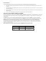
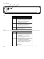
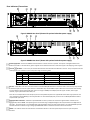
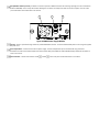
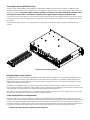
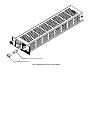
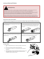
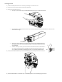
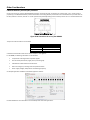
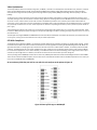
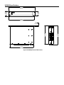
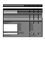
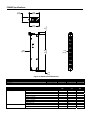
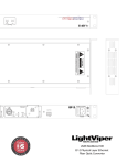
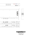
USER MANUAL Active Wave Division Multiplexer WDM16 / WDM8A / WDM8B Warning for Your Protection 1. Read these instructions. 2. Keep these instructions. 3. Heed all warnings. 4. Follow all instructions. 5. Do not use this apparatus near water. 6. Clean only with a dry cloth. 7. Do not block any of the ventilation openings. Install in accordance with the manufacturer’s instructions. 8. Do not install near any heat sources such as radiators, heat registers, stoves, or other apparatus (including amplifiers) that produce heat. 9. Do not defeat the safety purpose of the polarized or grounding‐type plug. A polarized plug has two blades with one wider than the other. A grounding type plug has two blades and a third grounding prong. The wide blade or the third prong is provided for your safety. If the provided plug does not fit into your outlet, consult an electrician for replacement of the obsolete outlet. 10. Protect the power cord from being walked on or pinched, particularly at plugs, convenience receptacles, and the point where they exit from the apparatus. 11. Only use attachments/accessories specified by the manufacturer. 12. Use only with the cart, stand, tripod, bracket, or table specified by the manufacturer, or sold with the apparatus. When a cart is used, use caution when moving the cart/apparatus combination to avoid injury from tip‐over. 13. Unplug this apparatus during lightning storms or when unused for long periods of time. 14. Refer all servicing to qualified service personnel. Servicing is required when the apparatus has been damaged in any way, such as power‐supply cord or plug is damaged, liquid has been spilled or objects have fallen into the apparatus, the apparatus has been exposed to rain or moisture, does not operate normally, or has been dropped. The apparatus shall not be exposed to dripping or splashing. No objects filled with liquids, such as vases, shall be placed on the apparatus. “WARNING: To reduce the risk of fire or electric shock, do not expose this apparatus to rain or moisture.” General Installation Instructions Please consider these general instructions in addition to any product‐specific instructions in the “Installation” chapter of this manual. Unpacking Check the equipment for any transport damage. If the unit is mechanically damaged, if liquids have been spilled or if objects have fallen into the unit, it must not be connected to the AC power outlet, or it must be immediately disconnected by unplugging the power cable. Repair must only be performed by trained personnel in accordance with the applicable regulations. Installation Site Install the unit in a place where the following conditions are met: The temperature and the relative humidity of the operating environment must be within the specified limits during operation of the unit. Values specified are applicable to the air inlets of the unit. Condensation may not be present during operation. If the unit is installed in a location subject to large variations of ambient temperature (e.g. in an OB‐van), appropriate precautions must be taken. Unobstructed airflow is essential for proper operation. Ventilation openings of the unit are a functional part of the design and must not be obstructed in any way during operation (e.g. ‐ by objects placed upon them, placement of the unit on a soft surface, or improper installation of the unit within a rack or piece of furniture). The unit must not be unduly exposed to external heat sources (direct sunlight, spot lights). Ambient Temperature Units and systems by FiberPlex are generally designed for an ambient temperature range (i.e. temperature of the incoming air) of 5 °C to 40 °C (41 °F to 104 °F). When rack mounting the units, the following facts must be considered: The permissible ambient temperature range for operation of the semiconductor components is 0 °C to +70 °C (32 °F to 158 °F) (commercial temperature range for operation). The airflow through the installation must allow exhaust air to remain cooler than 70 °C (158 °F) at all times. Average temperature increase of the cooling air shall be about 20 °C (68 °F), allowing for an additional maximum 10 °C increase at the hottest components. In order to dissipate 1 kW with this permissible average temperature increase, an air flow of 2.65 m³/min is required. Example: A rack dissipating P = 800 W requires an air flow of 0.8 * 2.65 m³/min which corresponds to 2.12 m³/min. If the cooling function of the installation must be monitored (e.g. for fan failure or illumination with spot lamps), the exhaust air temperature must be measured directly above the modules at several places within the enclosure. Grounding and Power Supply Grounding of units with mains supply (Class I equipment) is performed via the protective earth (PE) conductor integrated in three‐pin Phoenix™ connector. Units with battery operation (< 60 V, Class III equipment) must be earthed separately. Grounding the unit is one of the measures for protection against electrical shock hazard (dangerous body currents). Hazardous voltage may not only be caused by defective power supply insulation, but may also be introduced by the connected audio or control cables. This equipment may require the use of a different line cord, attachment plug, or both, depending on the available power source at installation. If the attachment plug needs to be changed, refer servicing to qualified personnel. Class I Equipment (Mains Operation) Should the equipment be delivered without a matching mains cable, the latter must be prepared by a trained person using the attached female plug (Neutrik™ powerCON TRUE1) with respect to the applicable regulations in your country. Before connecting the equipment to the AC power outlet, check that the local line voltage matches the equipment rating (voltage, frequency) within the admissible tolerance. The equipment fuses must be rated in accordance with the specifications on the equipment. Equipment supplied with a 3‐pole appliance inlet (protection conforming to class I equipment) must be connected to a 3‐pole AC power outlet so that the equipment cabinet is connected to the protective earth. WARNING: If the ground is defeated, certain fault conditions in the unit or in the system to which it is connected can result in full line voltage between chassis and earth ground. Severe injury or death can then result if the chassis and earth ground are touched simultaneously. Warranty, Service and Terms and Conditions of Sale For information about Warranty or Service information, please see our published ‘Terms and Conditions of Sale’. This document is available on fiberplex.com or can be obtained by requesting it from [email protected] or calling 301.604.0100. Disposal Disposal of Packing Materials The packing materials have been selected with environmental and disposal issues in mind. All packing material can be recycled. Recycling packing saves raw materials and reduces the volume of waste. If you need to dispose of the transport packing materials, recycling is encouraged. Disposal of Used Equipment Used equipment contains valuable raw materials as well as substances that must be disposed of professionally. Please dispose of used equipment via an authorized specialist dealer or via the public waste disposal system, ensuring any material that can be recycled has been. Please take care that your used equipment cannot be abused. After having disconnected your used equipment from the mains supply, make sure that the mains connector and the mains cable are made useless. Disclaimer The information in this document has been carefully checked and is believed to be accurate at the time of publication. However, no liability is assumed by FiberPlex for inaccuracies, errors, or omissions, nor for loss or damage resulting either directly or indirectly from use of the information contained herein. Introduction The FiberPlex WDM is an 8 or 16 Channel Wavelength Division Multiplexer, with each optical channel brought out to an SFP slot, so the user does not need to supply wavelength‐specific modules. Each channel can be linked via fiber with selected FiberPlex FOM or FOI fiber modules, FiberPlex LightViper™ or with virtually any third party fiber optic equipment with data rates from 155 megabits up to 3 gigabits per channel, for a possible maximum aggregate data rate of 48 gigabits. The user data enters and leaves the WDM via 16 SFP slots on the WDM16, or 8 slots on the WDM8A and WDM8B, which can be left unpopulated for unused channels, or populated with user‐supplied MSA‐compliant SFP modules that are appropriate for the user’s data rate, protocol and jitter requirements. Internally, these connect to fiber optic transceivers which are tuned to the specific wavelengths for the channels, which are then multiplexed onto the aggregate pair which connect to the other WDM(s) in the link. Data that enters a specific channel on one WDM will appear on the corresponding channel on the other WDM(s) in the link, with no interference with any other channels. Possible link configurations are: WDM16 to WDM16 – all 16 channels through WDM8A to WDM8A – all 8 channels through WDM8B to WDM8B – all 8 channels through The aggregate fibers from the WDM units exit the chassis via a duplex LC coupler, which connect to single mode fiber, up to 20 km in length. Since this is an aggregated wideband stream, any user equipment in the optical path (switches, couplers, etc.) must be able to accommodate the entire bandwidth without attenuation, and will not be able to receive or decode the stream digitally. The WDM units have provision for two (2) power supply modules for redundancy each having capacity to power the entire unit. An AC power input module is available now and a DC version is in development; both are ‘hot swappable’. Key Features 16 (or 8) Channel Active Wave Division Multiplexer Combines 16 (or 8) optical channels into a single fiber pair Each channel independently supports data rates from 155 MB up to 3 GB SMPTE compatible internal fiber optics, video optimized to support Pathological Signals Each optic channel can independently accept multimode or single mode optics, coax connection or CAT5 using flexible SFP modules Fully redundant, hot swappable power for ultimate reliability WDM Theory of Operation Infrared light has a frequency of approximately 400 Terahertz (400,000 Gigahertz). That is about 125,000 times higher than the data rate of a typical 3 Gigabit SFP, which means a large proportion of the bandwidth of a fiber optic cable is wasted. The current state of the art does not allow utilizing all of that bandwidth, but we can recover some of it by a technique called “Coarse Wave Division Multiplexing,” or “CWDM.” Essentially, it is the simple technique of taking each 3 Gigabit channel and using it to modulate a different frequency in that 400 Terahertz bandwidth. This is done through a series of optical filters and combiners, along with lasers and photodiodes tuned to a particular infrared center frequency. Historically, however, optics are referred to, not by their frequency, but by their wavelength, which is the speed of light divided by the frequency. In the traditional implementation of a CWDM, it is the user’s responsibility to provide the tailored SFPs and the CWDM itself, which may require adapters to interface with the user equipment. The Fiberplex WDM line, on the other hand, is an active WDM, with the wavelength‐specific components already tested and configured. Instead of a wavelength‐specific optical fiber, a generic SFP electrical interface is provided for each channel. Any SFP that conforms to the MSA can be inserted, even copper‐based SFPs like gigabit Ethernet, SDI, HDMI or MADI. The internal SFPs have a full 3 Gigabit bandwidth, video‐optimized. Generic fiber SFPs have limitations in passing video signals, since they do not maintain a constant DC level. The video‐optimized SFPs are constructed to better handle the shifting DC levels in video signals. Power Redundancy In order to remain functional, even in the event of component failures, the WDM employs the following redundancies: Two power supply slots, with load equalizing and protection circuitry on the backplane. Each supply has thermal and overcurrent protection. Each channel has its own independent power supply that runs off of the main power rails, so that a failure in one channel will leave the others operational. There is a microprocessor in the unit, but its function is purely monitoring. If it fails, the data will continue to flow unimpeded on all optical channels. There are two independent fan control channels, and two cooling fans on each side of the unit. Differences between WDM16, WDM8A and WDM8B The functional and physical characteristics of the WDM16, WDM8A and WDM8B are largely identical. The single differentiator is the number of Active Wave Division channels and the associated internal wavelengths that are supported. The chassis dimensions and power supplies remain identical. The WDM16 supports all of the 16 standard CWDM wavelengths of 1310‐1610 nm, whereas the WDM8 units support only 8 of those channels, so the installation can be scaled to the appropriate size. The WDM8A supports the upper 8 wavelengths 1470‐1610 nm and the WDM8B supports the lower 8 wavelengths 1310‐1450 nm. Because of the enormously flexible active nature of the WDM16/8, the wavelengths of the internal channels are basically invisible and even irrelevant to the end user. The reasons there are two subsets of wavelengths supported through the WDM8A and WDM8B is for future expandability of the line in providing the possibility of add/drop, combining and splitting capability. When only 8 channel point to point functionality is desired, the WDM8A should be the model of choice. Channels Internal Wavelengths WDM16 Model 16 1310‐1610 nm WDM8A 8 1470‐1610 nm WDM8B 8 1310‐1450 nm Getting Started Initial Inspection Immediately upon receipt, inspect the shipping container for damage. The container should be retained until the shipment has been checked for completeness and the equipment has been checked mechanically and electrically. If the shipment is incomplete, if there is mechanical damage, or if the unit fails to operate notify FiberPlex and make the shipping materials available for the carrier's inspection. Chassis Mounting Mount the chassis using fasteners appropriate to your standard 19” rack enclosure. All four (4) mounting points MUST be utilized. Ensure that there exists adequate clearance for front and rear ventilation. The chassis should be located in an environment where an ambient temperature between 0° and 50° C can be maintained. Front Indicators 1 2 3 Figure 1WDM16 Front Face Health – Multi‐function indicator displaying overall health of the unit. Color indications can be interpreted using the following table: LED State Condition Off No power to unit Red One or more of the following have occurred: Chassis temperature is dangerously high – shut down the unit or increase cooling immediately to prevent damage Both cooling fans are not functioning properly Hardware failure / Self‐Check failure Yellow One or more of the following have occurred: Chassis temperature is at the high end of the functional limit – check that the airflow temperature is within limits and that it is not restricted One of the cooling fans is not functioning properly Green Temperature is within range, fans are working properly and they system is functioning normally PS1 – Shows status indication of the power supply in PS Slot 1 (top slot). Color indications can be interpreted using the following table: LED State Condition Off No power supply installed Red One or more of the following have occurred: Power supply temperature is dangerously high – shut down the unit or increase cooling immediately to prevent damage Input power is present but output is out of range – replace the power supply Yellow One or more of the following have occurred: Power supply temperature is at the high end of the functional limit limit – check that the airflow temperature is within limits and that it is not restricted No input power is present – check the AC supply Communication to chassis cannot be established – replace the supply Green Temperature is within range and the power supply is functioning normally PS2 – Shows status indication of the power supply in PS Slot 2 (bottom slot). Color indications can be interpreted using the table above. Rear Indicators/Connections 4 5 6 7 8 9 10 Figure 2 WDM16 Rear Panel (shown with optional redundant power supply) 4 5 6 7 8 9 10 Figure 3 WDM8A Rear Panel (shown with optional redundant power supply) Power Supply Slots – At least one PSMAC must be installed in a slot for the unit to operate. The top slot is designated PS1 and the bottom slot is PS2. For full redundancy, power supplies can be installed in both slots. These slots support ‘hot swapping’ of the supplies. TX Fault RX Detect – There is one pair of these LED indicators associated with each SFP slot on the unit. They correspond to the slot directly below. Color indications can be interpreted using the following table: TX Fault RX Detect SFP Installed Transmitter Functioning* Receive Signal Present* Off Off No n/a n/a Red Red Yes No No Red Green Yes No Yes Green Red Yes Yes No Green Green Yes Yes Yes *Note that some copper Ethernet and Video SFPs may have custom TX Fault and RX Detect implementations. See SFP documentation of individual SFP for more information. SFP Slot – Install SFPs in this slot. These slots conform to the SFP MSA (INF‐8074i more information later in this manual). They are fixed bi‐directional ports and cannot support dual TX or dual RX SFPs. Any standard MSA complaint SFP can be used in these slots including but not limited to optical modules with data rates in the range of 155Mbps to 3.0Gbps, Ethernet copper modules, video copper modules, copper quadrax SFP to SFP cables, etc. Each channel is independent and will accept any format and any MSA compliant user supplied SFP module that is appropriate for the user’s equipment. Above 500 Mbps, ultra‐low jitter SFP’s are recommended (40 psec.) as well as ITU‐T G.652.D/IEC 60793‐2‐50.B1.3 compliant fiber optic cable. Aggregate Fiber Connection – A Neutrik™ opticalCON DUO connector provides a bi‐directional singlemode fiber interface to the aggregated I/O of the CWDM. This optical signal carries the data using all 16(8) wavelengths internally allocated to the 16(8) external SFP cages. This optical signal is not compatible with single wavelength passive or active optical devices. The opticalCON DUO provides for both a tactical connections using a mating opticalCON DUO cable or a standard connection with LC terminations. Health – This indicator serves the same function as the Health indicator on the front panel except it does not report the yellow condition. FAC (FiberPlex Auxiliary Control) – Dual RJ11 connections provide an RS422 connection for accessing reporting and control information from the WDM16/8. This is a daisy chained buss allowing the connection of multiple units with one control computer. The use of this port is described in more detail later in this manual. 11 12 13 Figure 4 PSMAC Power Supply Module AC Inlet – Power is provided through a Neutrik™ powerCON TRUE1 connector. Connect to 100‐240 VAC power source using the supplied AC power cord. Fuse Compartment – Contains the fuse for the power supply. The fuse compartment cap can be twisted off using a flat head screwdriver and the fuse removed. Replace fuse with a 2A time‐delay fuse (Littlefuse model 218.002 Slo‐Blo). Additional information is later in this manual. Status Indicator – Has the same function as PS1 and PS2 on the front panel as described earlier in this section. Power Requirements & PSM Mounting The power supply modules (PSMAC) accept voltages from 100‐240 VAC, 50/60 Hz. Maximum power consumption is 100W per module. Although the power supply modules are designed to be hot swappable, it is optimal practice to insert a module into the chassis prior to the application of AC power. The power supplies must be installed in the top most slot when viewing the insertion end of the respective model chassis. A secondary redundant power supply may be installed in the bottom slot. To access the fuses, disconnect power cord, and remove the power supply unit from the chassis. Replacement fuses must have the required current rating and must be of the specified type. Use of repaired fuses and/or bypass of the fuse holders is not recommended and will void the warranty. The system power requirement for a 17‐unit (maximum) rack configuration is 115 VAC @ 15 Amps; if supplied with 230 VAC, 8 Amps is required. Figure 5 Inserting Power Supply Using Redundant Power Supplies The WDM16/8 units come standard with a single PSMAC power supply installed. This configuration may be perfectly acceptable for many applications. In the case of mission critical applications which have zero tolerance for downtime, it is advisable to add a second optional PSMAC power supply for complete redundancy. The second supply can be inserted at any time in the unused power supply slot. Insert the supply first, then apply external AC power. The PSMAC and the WDM16/8 support ‘hot swapping’ of the power supplies. This means that either supply can be removed or inserted without powering down the unit. With two supplies installed, in the event of a failure of one PSMAC, the unit will continue to operate on the remaining supply. A new replacement can be installed and powered up without disturbing the unit. Best practice for utilizing redundant power is to connect each supply to a different power source or ‘phase’ of power. This way if one phase of power suffers an outage, the unit will continue to work on the remaining phase. Power Supply Module Fuse Replacement The power supply modules are each protected by a single 2A time‐delay fuse (Littlefuse model 218.002 Slo‐Blo). Replacement of the fuse requires the power cord to be disconnected from the power supply AC inlet and the power supply to be removed from the chassis. To access the fuse, use an appropriate sized flat head screwdriver and remove the Fuse Compartment Cap. The fuse will simply slide out of the Fuse Compartment with the cap removed. Slide a new fuse which meets the stated specifications into the Fuse Compartment and replace the cap. You may now re‐insert the power supply into the chassis and reconnect the power cord to the power supply AC inlet connector. Replace only with identical or equivalent time‐delay fuse. REMOVE CAP, REPLACE FUSE (SCREWDRIVER SLOT) Figure 6 Replacing the Fuse in the PSMAC Inserting and Removing SFP Modules Handling Warnings SFP Modules are static sensitive. To prevent damage from electrostatic discharge (ESD), it is recommended to attach an ESD preventative wrist strap to your wrist and to a bare metal surface when you install or remove an SFP Module. Disconnect all optical or copper cables from SFP Modules prior to installing or removing the SFP Module. Failure to do so could result in damage to the cable, cable connector or the SFP Module itself. Removing and inserting an SFP Module can shorten its useful life, so you should not remove and insert SFP Modules any more often than is absolutely necessary. Protect optical SFP modules by inserting clean dust covers into them after the cables are removed. Be sure to clean the optic surfaces of the fiber cables before you plug them back into the optical ports of another SFP module. Avoid getting dust and other contaminants into the optical ports of your SFP modules, because the optics will not work correctly when obstructed with dust. Identify the Latch Type of the SFP Module SFP Modules have various latching mechanisms to secure them into the SFP Cage of a device. The FiberPlex WDM can support a host of manufacturers and brands of SFP Modules so the user may encounter any number of different latches. Some of these are described below. Bail Clasp Actuator Button The bail clasp SFP module has a clasp that you use to remove or install the SFP module. The actuator button SFP module includes a button that you push in order to remove the SFP module from a port. This button can either lift ‘Up’ or press ‘In’ to release the SFP Module depending on the manufacturer. Mylar Tab Slide Tab The Mylar tab SFP module has a tab that you pull to remove the module from a port. The slide tab SFP module has a tab underneath the front of the SFP module that you use to disengage the module from a port. Inserting a Module 1) Attach an ESD‐preventative wrist or ankle strap, following its instructions for use. 2) Disconnect and remove all interface cables from SFP Module. 3) If the SFP Module has a Bail Clasp , close the Bail Clasp before inserting the SFP Module. 4) With the gold finger connector on the bottom and the label on the top, line up the SFP Module with the empty cage and slide it in making sure that it is completely inserted and seated in the cage. Removing a Module 1) Attach an ESD‐preventative wrist or ankle strap, following its instructions for use. 2) Disconnect and remove all interface cables from SFP Module. 3) Release the latching mechanism. Bail Clasp – Open the bail clasp on the SFP Module with your finger in a downward direction. Actuator Button – Gently press the actuator up (or in) while pulling the body of the SFP Module to release the SFP Module from the cage. Actuator Button 4) Mylar Tab – Pull the tab gently in a straight outward motion until it disengages from the port. Make sure the tab is not twisted when pulling as it may become disconnected from the SFP Module. Slide Tab ‐ With your thumb, push the slide tab on the bottom front of the SFP module in the direction of the equipment to disengage the module from the line card port. If you pull on the SFP module without disengaging the tab, you can damage the SFP module. Grasp the SFP Module between your thumb and index finger and carefully remove it from the port 5) Place the SFP Module on an antistatic mat, or immediately place it in a static shielding bag or container Connecting Aggregate Fiber Connection A Neutrik™ opticalCON DUO connector provides a bi‐directional singlemode fiber interface to the aggregated I/O of the CWDM. This optical signal carries the data using all 16(8) wavelengths internally allocated to the 16(8) external SFP cages. Due to its broad wavelength content, this optical signal is not compatible with single wavelength passive or active optical devices such as passive splitter, optical transceiver modules, etc. The opticalCON DUO provides for both a tactical connection using a mating opticalCON DUO cable or a standard connection with LC terminations. Making a Tactical Connection A tactical fiber connection can be achieved by simply utilizing a Neutrik™ opticalCON DUO fiber cable assembly for the aggregate fiber run. The opticalCON cable connector will simply ‘push’ into place. Disconnecting the cable requires grasping the cable connector with your full hand and pulling back the release ring with your thumb and fore finger while pulling the connector straight out. See Neutrik™ documentation for more information. Making a Standard LC Connection Standard singlmode LC connections can be made by simply plugging the LC cable connectors directly into the Neutrik™ opticalCON connector on the WDM16(8). When looking at the aggregate connector from the rear, the Transmit (TX) will be the LC connector on the left labeled ‘A’ and the Receive (RX) will be on the right labeled ‘B’. For clarification purposes, ‘Transmit (TX)’ means light will be emitted from this connector and ‘Receive (RX)’ means that light is expected to travel into the connector. TX RX Figure 7 Neutrik™ opticalCON DUO connector Making Other Fiber Connections Other sorts of singlemode fiber connections can be supported through the use of LC jumpers (not included). For example, ST fiber connections can be supported by using LC to ST fiber jumper cables and ST barrel connectors. Other Considerations FiberPlex Auxiliary Control (FAC) Interface On the rear of the unit, near the opticalCON DUO connector, are two RJ‐11 jacks, one marked “In” and the other, “Thru.” These support a proprietary, 115.2 kBaud RS‐422 serial protocol that enables a controlling device to poll the status of connected devices. Up to 255 units can be daisy‐chained on one link, with the “In” as the upstream link (eventually leading to the controller) and the “Thru” as the downstream link. Figure 8 FAC Control on the rear of the WDM16 The pinouts of the connectors are as follows: Connector Pin Function 1 Rx + (to the WDM) 2 RX – (to the WDM) 3 TX – (from the WDM) 4 TX+ (from the WDM) A standard crossover RJ11 cable can be used to daisychain units together. For the WDM, the following information can be accessed: Temperature of the logic board and power supplies Channel status (SFP inserted, signal present, transmit good) Identification of SFP models and manufacturer Status of cooling fans, including level and operational status Power supply Voltages, temperatures and switching frequency An example application available from FiberPlex appears as follows: Contact FiberPlex for more information as to availability of this and other applications. Video Optimization The Society of Motion Picture and Television Engineers, or SMPTE, is a leader in the development of standards for film, television, and other video. The Serial Digital Interface or SDI, was standardized by SMPTE for broadcast quality digital video transmission. Other standards evolved from this original standard, defining Enhanced, High‐definition (HD), 3G‐SDI (1080p) and Ultra High‐definition (UHD), or 4K video (2160p). To help ensure error‐free transmission, the standards include a data scrambler / descrambler to create a high density of transitions in the serial data, making it easier for the receiver to maintain timing. Where an encoding method such as 8B‐10B ensures a minimal sequential run of all ones or zeros, it does so at the cost of a 25% increase in bandwidth requirements. The scrambler / descrambler method does not require this, but as a result there are certain combinations of scrambler state and the next data bits to be scrambled that result in a sequence of up to twenty consecutive ones or zeros. These sequences are referred to as pathological conditions, and are present in specific shades of pink or grey. These pathological conditions may create errors in transmission through typical AC coupled optics, or any other AC coupled interface. Video Enhanced or SMPTE Compliant optics are designed to accept these pathological conditions, allowing the longer sequences of ones or zeros to pass without error. The Fiberplex Technologies WDM16 and WDM8 Active Coarse Wave Division Multiplexer has Video Enhanced optics pre‐installed internally on every port, ensuring error‐free transmission for all of your video requirements. SFP MSA Compliance The SFP Multi‐Source Agreement (MSA) is an agreement that was drafted among competing manufacturers of SFP optical modules. The SFF Committee was formed to oversee the creation and maintenance of these agreements including the SFP MSA designated as INF‐8074i. This agreement describes a mutually agreed upon standard for the form and function of SFP modules. However, not all SFPs produced are MSA compliant. The MSA provides for a transceiver (TX/RX) pinout. Other industries such as broadcast had the need for dual TX and dual RX SFP for uni‐directional applications such as video. Naturally, a non‐MSA standard was introduced allocating pinout assignments for dual output and dual input I/O configurations. In addition, the some of the internal serial communication pins were reassigned. The unique design of the WDM16/8 includes internal multi‐rate, CWDM optical SFPs which handle the wavelength allocation of the CWDM. These internal modules are MSA compliant, thus the external user accessible SFP modules must also be MSA compatible. For this reason you cannot use non‐MSA SFPs with the WDM16/8. Be sure that any SFPs that you wish to use with this unit conform to the pinout in Figure 9. Figure 9 Pinout of SFP cage on WDM16/8 WDM16 Specifications 3.00 [76.2] 3.47 [88.1] 19.00 [482.6] 18.33 [465.5] .25 [6.4] 17.25 [438.2] Figure 10 WDM16/8 Overall Dimensions 13.62 [ 346.0] 13.12 [ 333.2] PHYSICAL SPECIFICATIONS Case Dimensions (2U) Length 13 in (330 mm) Width 19 in (482 mm) Height 3.5 in (133 mm) Weight 16.6 lb (7.5 kg) ELECTRICAL SPECIFICATIONS Power Requirement with PSMAC Min 90 ‐ 36 ‐ Typ ‐ 65 ‐ 65 Max 230 ‐ 72 ‐ External SFP Interfaces (1‐16) Min Typ Max Data Rate (MB) Power Requirement with PSMDC Voltage Range (VAC) Power Consumption (W) Voltage Range (VDC) Power Consumption (W) 155 ‐ 3000 Recommended Jitter (psec) ‐ 40 ‐ Operating Voltage (VDC) ‐ 3.3 Maximum Current (mA) ‐ ‐ 350 Min Typ Max Internal CDWM Optical Interfaces Aggregate Optical Launch Level (dB) ‐1 0 +1 Aggregate Receiver Sensitivity ‐25 ‐24.5 ‐22 CWDM Wavelengths Ch1 ‐ 1610nm Ch2 ‐ 1590nm Ch3 ‐ 1570nm Ch4 ‐ 1550nm Ch5 ‐ 1530nm Ch6 ‐ 1510nm Ch7 ‐ 1490nm Ch8 ‐ 1470nm Ch9 ‐ 1450nm Ch10 ‐ 1430nm Ch11 ‐ 1410nm Ch12 ‐ 1390nm Ch13 ‐ 1370nm Ch14 ‐ 1350nm Ch15 ‐ 1330nm Ch16 ‐ 1310nm Environmental Storage Temperature (°C) Operating Temperature (°C) ‐40 ‐ 85 0 ‐ 50 Aggregate Interface Connector Neutrik opticalCON DUO (LC) PSMAC Specifications 3.30 [83.9] 2.97 [75.4] .62 [15.9] 1.31 [33.2] 10.98 [279.0] 2.63 [66.9] 1.26 [32.0] .30 [7.5] Figure 11 PSMAC Overall Dimensions PHYSICAL SPECIFICATIONS Length 11.25 in (286 mm) Dimensions Width 2.625 in (67 mm) Height 1.25 in (32 mm) Weight 1.1 lb (0.5 kg) SPECIFICATIONS ‐ AC POWER SUPPLY Power Supply Environmental Input Voltage (VAC) Input Frequency (Hz) Power Factor (%) Output 1Voltage (VDC) Output 1 Current (A) Output 2 Voltage (VDC) Output 1 Current (A) Supply Current (A) Ouput Power (W) Storage Temperature (°C) Operating Temperature (°C) Min 100 40 ‐ 5.04 ‐ 45.6 ‐ ‐ ‐40 0 Typ 110 ‐ 92 5.3 7 48 1.3 1.3 100 ‐ ‐ Max 240 400 ‐ 5.57 ‐ 50.4 ‐ ‐ 85 50 WDMUM‐1401 18040-412 Guilford Rd. • Annapolis Junction, MD 20701 fiberplex.com • [email protected] • 301.604.0100