1
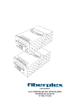
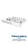
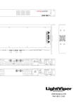
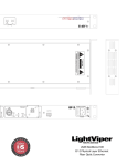
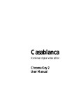
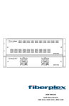
USER MANUAL Flexible Interface SFP/SFP+ Workbox FOI‐6010 / TD‐6010 Warning for Your Protection 1. Read these instructions. 2. Keep these instructions. 3. Heed all warnings. 4. Follow all instructions. 5. Do not use this apparatus near water. 6. Clean only with a dry cloth. 7. Do not block any of the ventilation openings. Install in accordance with the manufacturer’s instructions. 8. Do not install near any heat sources such as radiators, heat registers, stoves, or other apparatus (including amplifiers) that produce heat. 9. Do not defeat the safety purpose of the polarized or grounding‐type plug. A polarized plug has two blades with one wider than the other. A grounding type plug has two blades and a third grounding prong. The wide blade or the third prong is provided for your safety. If the provided plug does not fit into your outlet, consult an electrician for replacement of the obsolete outlet. 10. Protect the power cord from being walked on or pinched, particularly at plugs, convenience receptacles, and the point where they exit from the apparatus. 11. Only use attachments/accessories specified by the manufacturer. 12. Use only with the cart, stand, tripod, bracket, or table specified by the manufacturer, or sold with the apparatus. When a cart is used, use caution when moving the cart/apparatus combination to avoid injury from tip‐over. 13. Unplug this apparatus during lightning storms or when unused for long periods of time. 14. Refer all servicing to qualified service personnel. Servicing is required when the apparatus has been damaged in any way, such as power‐supply cord or plug is damaged, liquid has been spilled or objects have fallen into the apparatus, the apparatus has been exposed to rain or moisture, does not operate normally, or has been dropped. The apparatus shall not be exposed to dripping or splashing. No objects filled with liquids, such as vases, shall be placed on the apparatus. “WARNING: To reduce the risk of fire or electric shock, do not expose this apparatus to rain or moisture.” General Installation Instructions Please consider these general instructions in addition to any product‐specific instructions in the “Installation” chapter of this manual. Unpacking Check the equipment for any transport damage. If the unit is mechanically damaged, if liquids have been spilled or if objects have fallen into the unit, it must not be connected to the AC power outlet, or it must be immediately disconnected by unplugging the power cable. Repair must only be performed by trained personnel in accordance with the applicable regulations. Installation Site Install the unit in a place where the following conditions are met: The temperature and the relative humidity of the operating environment must be within the specified limits during operation of the unit. Values specified are applicable to the air inlets of the unit. Condensation may not be present during operation. If the unit is installed in a location subject to large variations of ambient temperature (e.g. in an OB‐van), appropriate precautions must be taken. Unobstructed airflow is essential for proper operation. Ventilation openings of the unit are a functional part of the design and must not be obstructed in any way during operation (e.g. ‐ by objects placed upon them, placement of the unit on a soft surface, or improper installation of the unit within a rack or piece of furniture). The unit must not be unduly exposed to external heat sources (direct sunlight, spot lights). Ambient Temperature Units and systems by FiberPlex are generally designed for an ambient temperature range (i.e. temperature of the incoming air) of 5 °C to 40 °C (41 °F to 104 °F). When rack mounting the units, the following facts must be considered: The permissible ambient temperature range for operation of the semiconductor components is 0 °C to +70 °C (32 °F to 158 °F) (commercial temperature range for operation). The airflow through the installation must allow exhaust air to remain cooler than 70 °C (158 °F) at all times. Average temperature increase of the cooling air shall be about 20 °C (68 °F), allowing for an additional maximum 10 °C increase at the hottest components. If the cooling function of the installation must be monitored (e.g. for fan failure or illumination with spot lamps), the exhaust air temperature must be measured directly above the modules at several places within the enclosure. Grounding and Power Supply Grounding of units with mains supply (Class I equipment) is performed via the protective earth (PE) conductor integrated in three‐pin Phoenix™ connector. Units with battery operation (< 60 V, Class III equipment) must be earthed separately. Grounding the unit is one of the measures for protection against electrical shock hazard (dangerous body currents). Hazardous voltage may not only be caused by defective power supply insulation, but may also be introduced by the connected audio or control cables. This equipment may require the use of a different line cord, attachment plug, or both, depending on the available power source at installation. If the attachment plug needs to be changed, refer servicing to qualified personnel. Warranty, Service and Terms and Conditions of Sale For information about Warranty or Service information, please see our published ‘Terms and Conditions of Sale’. This document is available on fiberplex.com or can be obtained by requesting it from [email protected] or calling 301.604.0100. Disposal Disposal of Packing Materials The packing materials have been selected with environmental and disposal issues in mind. All packing material can be recycled. Recycling packing saves raw materials and reduces the volume of waste. If you need to dispose of the transport packing materials, recycling is encouraged. Disposal of Used Equipment Used equipment contains valuable raw materials as well as substances that must be disposed of professionally. Please dispose of used equipment via an authorized specialist dealer or via the public waste disposal system, ensuring any material that can be recycled has been. Please take care that your used equipment cannot be abused. After having disconnected your used equipment from the mains supply, make sure that the mains connector and the mains cable are made useless. Disclaimer The information in this document has been carefully checked and is believed to be accurate at the time of publication. However, no liability is assumed by FiberPlex for inaccuracies, errors, or omissions, nor for loss or damage resulting either directly or indirectly from use of the information contained herein. Notice The firmware included in this product utilizes the Atmel Software Framework (ASF), Copyright (c) 2011 ‐ 2012 Atmel Corporation. All rights reserved. Redistribution and use in source and binary forms, with or without modification, are permitted provided that the following conditions are met: 1. Redistributions of source code must retain the above copyright notice, this list of conditions and the following disclaimer. 2. Redistributions in binary form must reproduce the above copyright notice, this list of conditions and the following disclaimer in the documentation and/or other materials provided with the distribution. 3. The name of Atmel may not be used to endorse or promote products derived from this software without specific prior written permission. 4. This software may only be redistributed and used in connection with an Atmel micro‐controller product. THIS SOFTWARE IS PROVIDED BY ATMEL “AS IS” AND ANY EXPRESS OR IMPLIED WARRANTIES, INCLUDING, BUT NOT LIMITED TO, THE IMPLIED WARRANTIES OF MERCHANTABILITY, FITNESS FOR A PARTICULAR PURPOSE AND NON‐INFRINGEMENT ARE EXPRESSLY AND SPECIFICALLY DISCLAIMED. IN NO EVENT SHALL ATMEL BE LIABLE FOR ANY DIRECT, INDIRECT, INCIDENTAL, SPECIAL, EXEMPLARY, OR CONSEQUENTIAL DAMAGES (INCLUDING, BUT NOT LIMITED TO, PROCUREMENT OF SUBSTITUTE GOODS OR SERVICES; LOSS OF USE, DATA, OR PROFITS; OR BUSINESS INTERRUPTION) HOWEVER CAUSED AND ON ANY THEORY OF LIABILITY, WHETHER IN CONTRACT, STRICT LIABILITY, OR TORT (INCLUDING NEGLIGENCE OR OTHERWISE) ARISING IN ANY WAY OUT OF THE USE OF THIS SOFTWARE, EVEN IF ADVISED OF THE POSSIBILITY OF SUCH DAMAGE. Introduction The true “Swiss Army Knife” of fiber optic transport, the FOI‐6010 in conjunction with any combination of a myriad of FiberPlex or third party SFP/SFP+ (Small Form‐Factor Pluggable) optical & electrical modules, allows you to transport what you want, when you want it, how you want it, wherever you want it; all over one product solution... The FiberPlex FOI‐6010 and SFP/ SFP+ module should be in everyone’s toolbox. Key Features Ultra flexible SFP+ to SFP+ interface Supports Data Rates up to 12.5 Gbps USB interface for full access to all SFP standard and custom registers Limitless Conversion applications including but not limited to: o Video distribution (multi‐drop) o 100Base‐SX to 100Base‐FX Conversion o 100Base‐FX or SX to 100Base LX10 Conversion o Analog Video to Fiber Conversion o Dual fiber to single fiber conversion by using BiDi SFP's o Ethernet to Fiber Conversion o Usable range extension to Layer 2 Media Networking Technologies, such as; Aviom™, CobraNet®, Dante™ and EtherSound® o HD‐SDI to HDMI Conversion o SD‐SDI (composite) to HD video conversion o MADI to Fiber Conversion o OM1/OM2 to OM3 Multi‐mode Conversion o Optical Repeater o Multimode to Singlemode Fiber Conversion o Optical Wavelength Conversion Theory of Operation Many sorts of interfaces, not just fiber, are now available in the SFP/SFP+ format, including Full HD video and networking. On the user, connector side, they support the signals appropriate to those protocols, but then convert them internally to a standard stream of high‐speed serial data. The FOI/TD‐6010 connects those standard streams together, so that the different interface protocols can talk the same language. Since the fiber‐based SFPs are the most generic, it is usually possible to connect, not only two different copper interfaces together in the same FOI/TD‐6010, but also to interpose a fiber link between them. Since the range of signals over fiber is so much greater than that of copper, this allows significant expansion of the range of those protocols. SFPs also have an additional, low‐speed serial interface that provides identification, monitoring and also control of the devices through the processor in the FOI/TD‐6010. Differences between FOI‐6010 and TD‐6010 Functionally, the FOI‐6010 and TD‐6010 are identical. The only differences are the packaging and power supply. The FOI‐6010 is part of the FOI line of products designed for ruggedized mil applications. It is housed in the familiar FOI shielded can enclosure. For standalone applications it can be powered by adding a PSQ‐4909 AC supply or a PSQ‐4920 DC power supply (not included). Optionally, up to 8 FOI units can be mounted on CMA chassis adapters and installed in an RMC‐3101 or RMC‐2101 rack mount chassis. The units are powered redundantly by a common back plane connection. The TD‐6010 is housed in the commercial ‘Throw Down’ packaging. This version is designed to be a workhorse unit in various commercial and industrial environments. It is powered either by a 9VDC ‘Wall Wart’ style supply (included) or via bussed power supplied through an integrated three‐pin Phoenix™ connector. Up to six TD‐6010 units can be installed in the optional 1U TDR‐01 rack shelf. Getting Started Initial Inspection Immediately upon receipt, inspect the shipping container for damage. The container should be retained until the shipment has been checked for completeness and the equipment has been checked mechanically and electrically. If the shipment is incomplete, if there is mechanical damage, or if the unit fails to operate notify FiberPlex and make the shipping materials available for the carrier's inspection. Front Indicators/Connections 3 4 5 7 6 2 1 Figure 1 TD‐6010 (left) and FOI‐6010 (right) Front Face SFP Port A – Install SFPs in this slot. These slots conform to the SFP MSA (INF‐8074i more information later in this manual) as well as non‐MSA pinouts. They can be both fixed bi‐directional ports and support dual TX or dual RX SFPs. Any standard MSA or non‐MSA complaint SFP can be used in these slots including but not limited to optical modules with data rates in the range of 155Mbps to 12.5 Gbps, Ethernet copper modules, video copper modules, copper quadrax SFP to SFP cables, etc. Each channel is independent and will accept any format and any user supplied SFP module that is appropriate for the user’s equipment. Above 500 Mbps, ultra‐low jitter SFP’s are recommended (40 psec.) as well as ITU‐T G.652.D/IEC 60793‐2‐50.B1.3 compliant fiber optic cable. SFP Port B – A second SFP slot functionally equivalent to SFP Port A. Any SFP installed in this slot will be directly electrically connected to the SFP in Port A. Any signals presented in the Receive of Port A will exit on the Transmit of Port B and vice versa. TX Fault RX Detect – There is one pair of these LED indicators associated with each SFP slot on the unit. They correspond to the slot directly below. Color indications can be interpreted using the following table: TX Fault RX Detect SFP Installed Transmitter Functioning* Receive Signal Present* Off Off No n/a n/a Red Red Yes No No Red Green Yes No Yes Green Red Yes Yes No Green Green Yes Yes Yes *Note that some copper Ethernet and Video SFPs may have custom TX Fault and RX Detect implementations. See SFP documentation of individual SFP for more information. Power – LED which indicates the presence of DC power in the unit. Note that on start‐up, the unit will perform a quick lamp check, flashing all LEDs Power Indicator Off No power from the external supply or internal fault Blue Power supply is operating properly uFAC – USB 2.0 Micro‐B connector for configuration and monitoring of SFP registers. Requires a USB connection to a PC or MAC computer with the FiberPlex uFAC‐6010 software installed. Status – LED which indicates the health status of the unit. The LED can be interpreted according to the following table. Status Indicator Off Green Amber Red If Power LED is on, there is an internal failure inside the FOI. Replace Power supply is operating properly At limit of normal range of temperature, apply more cooling to the unit Exceeding temperature limits or internal failure Rear Indicators/Connections 8 8 9 Figure 2 TD‐6010 (left) and FOI‐6010 (right) Rear Face Circular DC Power Connection – DC power entry for the unit. On the FOI‐6010 this is a Lemo connector designed to interface with either a PSQ power module or RMC chassis. On the TD‐6010 this is a standard DC connection for use with the included DC wall power supply. Phoenix CD Power Connection – Secondary power option for the TD‐6010. This is wired in direct parallel with the Circular connector and has the addition of a positive earth chassis ground connection. This can be used to power the unit on a client supplied power buss. Figure 3 FOI‐6010 Installed in an RMC‐3101 Chassis Power Requirements and Mounting Flexible mounting allows the FOI‐6010 to be chassis mounted or standalone configuration. Any combination of 8 FiberPlex FOI units can be mounted in a RMC‐3101 using CMA‐2001 chassis mount adapters. The RMC‐3101 can accommodate hot swapped redundant power. Alternately, the FOI‐6010 can be used in a standalone application when paired with a PSQ‐4909 for full range AC operation or the PSQ‐4920 for 12‐48VDC operation. Figure 4 FOI‐6010 with PSQ‐4909 (left) and FOI‐6010 with CMA‐3002 (right) Lower TD Unit Over Screw Heads, #2 Wood Screw, 1/2" Long, #1 Phillips Drive Figure 6 TD‐6010 installation on a TDR‐01 tray Figure 5 Installing a TD‐6010 Using Mounting Slots Inserting and Removing SFP Modules Handling Warnings SFP Modules are static sensitive. To prevent damage from electrostatic discharge (ESD), it is recommended to attach an ESD preventative wrist strap to your wrist and to a bare metal surface when you install or remove an SFP Module. Disconnect all optical or copper cables from SFP Modules prior to installing or removing the SFP Module. Failure to do so could result in damage to the cable, cable connector or the SFP Module itself. Removing and inserting an SFP Module can shorten its useful life, so you should not remove and insert SFP Modules any more often than is absolutely necessary. Protect optical SFP modules by inserting clean dust covers into them after the cables are removed. Be sure to clean the optic surfaces of the fiber cables before you plug them back into the optical ports of another SFP module. Avoid getting dust and other contaminants into the optical ports of your SFP modules, because the optics will not work correctly when obstructed with dust. Identify the Latch Type of the SFP Module SFP Modules have various latching mechanisms to secure them into the SFP Cage of a device. The FiberPlex WDM can support a host of manufacturers and brands of SFP Modules so the user may encounter any number of different latches. Some of these are described below. Bail Clasp Actuator Button The bail clasp SFP module has a clasp that you use to remove or install the SFP module. The actuator button SFP module includes a button that you push in order to remove the SFP module from a port. This button can either lift ‘Up’ or press ‘In’ to release the SFP Module depending on the manufacturer. Mylar Tab Slide Tab The Mylar tab SFP module has a tab that you pull to remove the module from a port. The slide tab SFP module has a tab underneath the front of the SFP module that you use to disengage the module from a port. Inserting a Module 1) 2) 3) 4) Attach an ESD‐preventative wrist or ankle strap, following its instructions for use. Disconnect and remove all interface cables from SFP Module. If the SFP Module has a Bail Clasp , close the Bail Clasp before inserting the SFP Module. With the gold finger connector on the bottom and the label on the top, line up the SFP Module with the empty cage and slide it in making sure that it is completely inserted and seated in the cage. Removing a Module 1) 2) 3) Attach an ESD‐ preventative wrist or ankle strap, following its instructions for use. Disconnect and remove all interface cables from SFP Module. Release the latching mechanism. Bail Clasp – Open the bail clasp on the SFP Module with your finger in a downward direction. Actuator Button – Gently press the actuator up (or in) while pulling the body of the SFP Module to release the SFP Module from the cage. Mylar Tab – Pull the tab gently in a straight outward motion until it Actuator Button disengages from the port. Make sure the tab is not twisted when pulling as it may become disconnected from the SFP Module. Slide Tab ‐ With your thumb, push the slide tab on the bottom front of the SFP module in the direction of the equipment to disengage the module from the line card port. If you pull on the SFP module without disengaging the tab, you can damage the SFP module. 4) Grasp the SFP Module between your thumb and index finger and carefully remove it from the port 5) Place the SFP Module on an antistatic mat, or immediately place it in a static shielding bag or container Other Considerations USB FiberPlex Auxilary Control (uFAC) Interface The FOI‐6010 includes a uFAC (FiberPlex Auxiliary Control over USB) interface which allows read write access to status and parameter registers in both installed SFP/ SFP+ modules if supported by Fiberplex. This port communicates over a USB 2.0‐compliant, full speed connection, via a USB Micro‐B connector. It enumerates as a custom Fiberplex device, requiring its own driver. Please contact Fiberplex Technologies for details and availability of the applications built around this interface. Although power can be supplied across the port, it is recommended that the appropriate external supply for the TD/FOI‐6010 be used. Power supplied through the USB port itself is not sufficient to power the device with SFPs installed. Video Optimization The Society of Motion Picture and Television Engineers, or SMPTE, is a leader in the development of standards for film, television, and other video. The Serial Digital Interface or SDI, was standardized by SMPTE for broadcast quality digital video transmission. Other standards evolved from this original standard, defining Enhanced, High‐definition (HD), 3G‐SDI (1080p) and Ultra High‐definition (UHD), or 4K video (2160p). To help ensure error‐free transmission, the standards include a data scrambler / descrambler to create a high density of transitions in the serial data, making it easier for the receiver to maintain timing. Where an encoding method such as 8B‐10B ensures a minimal sequential run of all ones or zeros, it does so at the cost of a 25% increase in bandwidth requirements. The scrambler / descrambler method does not require this, but as a result there are certain combinations of scrambler state and the next data bits to be scrambled that result in a sequence of up to twenty consecutive ones or zeros. These sequences are referred to as pathological conditions, and are present in specific shades of pink or grey. These pathological conditions may create errors in transmission through typical AC coupled optics, or any other AC coupled interface. Video Enhanced or SMPTE Compliant optics are designed to accept these pathological conditions, allowing the longer sequences of ones or zeros to pass without error. SFP MSA Compliance The SFP Multi‐Source Agreement (MSA) is an agreement that was drafted among competing manufacturers of SFP optical modules. The SFF Committee was formed to oversee the creation and maintenance of these agreements including the SFP MSA designated as INF‐8074i. This agreement describes a mutually agreed upon standard for the form and function of SFP modules. However, not all SFPs produced are MSA compliant. The MSA provides for a transceiver (TX/RX) pinout. Other industries such as broadcast had the need for dual TX and dual RX SFP for unidirectional applications such as video. Naturally, a non‐MSA standard was introduced allocating pinout assignments for dual output and dual input I/O configurations. In addition, the some of the internal serial communication pins were reassigned. The FOI/TD‐6010 will accept any of these pinout schemes in any combination. For example you can have an MSA compliant SFP in the A position and a non‐MSA SFP in the B position. Of course, functionality will be dependent on using functionally compatible modules. (e.g. Two Dual RX modules will not have any functionality) Any of the pinout schemes in the following table are acceptable in either SFP slot. Pinout Comparison Chart PIN 1 2 3 4 5 6 7 8 9 10 11 12 13 14 15 16 17 18 19 20 Transceiver (MSA) VEE TX_FAULT [VEE] TX_DIS MOD_DEF(2) ‐ SDA MOD_DEF(1) ‐ SCL MOD_DEF(0) – PRESENCE [VEE] Rate [NC] LOS VEE VEE VEE RD‐ RD+ VEE VCC VCC VEE TD+ TD‐ VEE Transceiver (Non‐MSA) VEE VEE NC VEE SCL SDA VEE RX1_LOS NC NC VEE Rx1‐ Rx1+ VEE VCC VCC VEE Tx1+ Tx1‐ Tx1_DIS Dual TX (Non‐MSA) VEE NC NC VEE SCL SDA VEE Tx2+ Tx2‐ Tx2_DIS VEE NC NC VEE VCC VCC VEE Tx1+ Tx1‐ Tx1_DIS Dual RX (Non‐MSA) VEE Rx2‐ Rx2+ VEE SCL SDA VEE NC NC NC VEE Rx1‐ Rx1+ VEE VCC VCC VEE NC NC NC Specifications 4.50 [114.3] .42 [10.6] .13 [3.2] .11 [2.9] 1.45 [36.9] 2.56 [65.1] Figure 7 FOI‐6010 Dimensions .11 [2.9] 4.50 [114.3] .14 [3.5] .15 [3.8] 2.00 [50.8] 1.66 [42.1] 2.75 [69.8] Figure 8 TD‐6010 Dimensions ELECTRICAL SPECIFICATIONS Voltage Range Supply Current, no SFPs Supply Current, max 2 SFP+ Power Requirement Environmental Min 5 21 ‐ Storage Temperature ‐40 OperatingTemperature 0 Full speed USB 2.0 compliant Micro‐B Device Min 155 ‐ ‐ ‐ Typ 9 23 500 Max 40 30 600 unit VDC mA mA ‐ ‐ 85 50 °C °C Interface External SFP Interfaces Typ Max Data Rate ‐ 12,500 Recommended Jitter 40 ‐ Operating Voltage 3.3 Maximum Current ‐ 500 Optical Modules 2 SFP+ MSA (SFF‐8431, SFF‐8432, SFF‐8433) compliant slots, data rate 0 – 12.5 gigabits unit Mb Psec VDC mA PHYSICAL SPECIFICATIONS Case Dimensions FOI‐6010 TD‐6010 Size 4 Length 4.5 in (114 mm) 4.5 in (114 mm) Width 1.453 in (37 mm) 1.66 in (42 mm) Height 2.56 in (65 mm) 2.75 in (70 mm) Weight 2.0 lb (0.9 kg) 0.4 lb (0.2 kg) 6010UM‐1403 18040-412 Guilford Rd. • Annapolis Junction, MD 20701 fiberplex.com • [email protected] • 301.604.0100