1
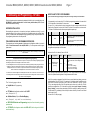
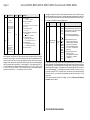
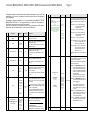
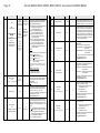
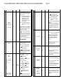
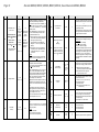
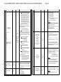
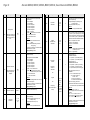
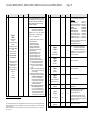
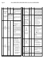
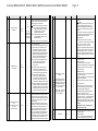
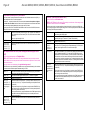
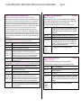
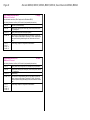
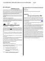
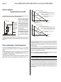
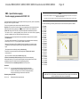
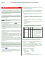
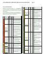
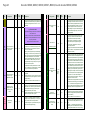
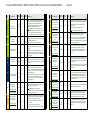
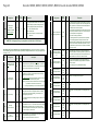
Decoder MX620, MX621, MX630, MX631, MX632 Sound decoder MX640, MX642 3. Addressing and Programming – CV table Page 7 HELPFUL HINTS FOR CV PROGRAMMING: If you are familiar with CV programming please skip this section and go directly to the CV table below! Every loco decoder requires a separate unique address with which the loco is controlled using a cab. All NMRA-DCC compliant decoders have 3 as their factory default address (NMRA standardized decoder address at delivery). CV programming is not the same for all CV‟s. While the programming procedure is the same for all CV‟s, the calculation of the individual CV values varies. DECODER INSTALLATION: For some CV‟s it is obvious what the value is supposed to be and can easily be derived from the “Range” and/or “Description” column in the CV table. This kind of CV acts similar to a volume control. For instance, CV#2 determines the minimum speed applied at speed step 1: After installing the new decoder in a locomotive (see chapter “Installation and wiring”), it can be tested with address #3. As a minimum, either the motor or headlights need to be connected (better yet both), to enable decoder acknowledgment during programming. Doing a complete installation before programming the decoder is often more practical. CV Designation Vstart THE ADDRESSING AND PROGRAMMING PROCEDURE: The programming and read-out procedure of addresses and configuration variables is covered in detail in the instruction manual for the cab (MX21, MX31....). For other systems consult the appropriate manual. Programming a decoder with a PC and ADaPT software (by E.Sperrer, software developer) is a lot easier and more convenient! Range 1 – 252 (See add. notes) Default 2 Designation Range Default Technical note to decoder acknowledgments during programming: The following pages show: Helpful hints for CV programming next CV tables with configuration variables from #1 to #255 next (Chapter 4 & 5): Additional Notes (CV‟s) and Function Mapping next (Chapter 6, only valid for sound decoders): ZIMO SOUND Selection and Programming; description of basic functionality, operating procedures and CV TABLES with configuration variables from #256 to #511, valid for all types of the MX640 sound decoder family Bit 4 in CV # 29 has to be 0; otherwise individual speed table is active. Another similar CV is the “dimming” factor in CV #60: When programming or reading CV’s with the DCC system or a computer, each successful programming step will be acknowledged by the decoder and displayed on the cab and/or monitor. The decoder won’t use the headlights for acknowledgment if CV #60 is set to a value of 40 or less. This is to prevent damage to bulbs since this setting is often used in conjunction with low voltage bulbs. The motor is then the only load used for acknowledgments. Entered value = internal speed step assigned to lowest cab speed step. The “range” column states that any value from 1 to 252 may be used. The higher the value the faster the engine runs at speed step 1 and vice versa. CV The acknowledgment is based on short power pulses that the decoder generates by briefly turning the motor and headlights on, which the command station recognizes (at the programming track output). It follows that the acknowledgment and read out of a decoder is only successful if the current consumption is high enough, which means that the motor and headlights have to be connected or at least one of the two. Description #60 Reduced function output voltage (Dimming) Description The actual function output voltage can be reduced by PWM. Useful to dim headlights, for example. 0 - 255 0 Example values: # 60 = 0 or 255: full voltage # 60 = 170: 2/3 of full voltage. # 60 = 204: 80% of full voltage. Again, the range column states that any value from 1 to 252 may be used and in the “description” column it is explained that the brightness of the light increases with the value. Other CV‟s are easier to understand if you think of them as a small switch board, where you can turn individual switches ON or OFF. Such a CV is made up of 8 “individual switches” called Bits and the group of Bits is known as a Byte (which is the CV itself or the switch board, if you will). On some CV‟s you can change the setting of all 8 Bits (switches) and on others only a select few. The Bits (switches) are numbered from 0 to 7 and each has a specific value (see the chapter “Converting binary to decimal” for more on binary calculations). Each Bit is turned ON by adding its value to the CV and turned OFF by subtracting its value. Add up the values of each Bit you want to turn ON and enter the total to the CV. One such CV is CV #29 (next page):