1
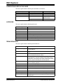
INIC Explorer User’s Guide 2009-2014 Microchip Technology Inc. DS60001306A Note the following details of the code protection feature on Microchip devices: • Microchip products meet the specification contained in their particular Microchip Data Sheet. • Microchip believes that its family of products is one of the most secure families of its kind on the market today, when used in the intended manner and under normal conditions. • There are dishonest and possibly illegal methods used to breach the code protection feature. All of these methods, to our knowledge, require using the Microchip products in a manner outside the operating specifications contained in Microchip’s Data Sheets. Most likely, the person doing so is engaged in theft of intellectual property. • Microchip is willing to work with the customer who is concerned about the integrity of their code. • Neither Microchip nor any other semiconductor manufacturer can guarantee the security of their code. Code protection does not mean that we are guaranteeing the product as “unbreakable.” Code protection is constantly evolving. We at Microchip are committed to continuously improving the code protection features of our products. Attempts to break Microchip’s code protection feature may be a violation of the Digital Millennium Copyright Act. If such acts allow unauthorized access to your software or other copyrighted work, you may have a right to sue for relief under that Act. Information contained in this publication regarding device applications and the like is provided only for your convenience and may be superseded by updates. It is your responsibility to ensure that your application meets with your specifications. MICROCHIP MAKES NO REPRESENTATIONS OR WARRANTIES OF ANY KIND WHETHER EXPRESS OR IMPLIED, WRITTEN OR ORAL, STATUTORY OR OTHERWISE, RELATED TO THE INFORMATION, INCLUDING BUT NOT LIMITED TO ITS CONDITION, QUALITY, PERFORMANCE, MERCHANTABILITY OR FITNESS FOR PURPOSE. Microchip disclaims all liability arising from this information and its use. Use of Microchip devices in life support and/or safety applications is entirely at the buyer’s risk, and the buyer agrees to defend, indemnify and hold harmless Microchip from any and all damages, claims, suits, or expenses resulting from such use. No licenses are conveyed, implicitly or otherwise, under any Microchip intellectual property rights. Trademarks The Microchip name and logo, the Microchip logo, dsPIC, FlashFlex, flexPWR, JukeBlox, KEELOQ, KEELOQ logo, Kleer, LANCheck, MediaLB, MOST, MOST logo, MPLAB, OptoLyzer, PIC, PICSTART, PIC32 logo, RightTouch, SpyNIC, SST, SST Logo, SuperFlash and UNI/O are registered trademarks of Microchip Technology Incorporated in the U.S.A. and other countries. The Embedded Control Solutions Company and mTouch are registered trademarks of Microchip Technology Incorporated in the U.S.A. Analog-for-the-Digital Age, BodyCom, chipKIT, chipKIT logo, CodeGuard, dsPICDEM, dsPICDEM.net, ECAN, In-Circuit Serial Programming, ICSP, Inter-Chip Connectivity, KleerNet, KleerNet logo, MiWi, MPASM, MPF, MPLAB Certified logo, MPLIB, MPLINK, MultiTRAK, NetDetach, Omniscient Code Generation, PICDEM, PICDEM.net, PICkit, PICtail, RightTouch logo, REAL ICE, SQI, Serial Quad I/O, Total Endurance, TSHARC, USBCheck, VariSense, ViewSpan, WiperLock, Wireless DNA, and ZENA are trademarks of Microchip Technology Incorporated in the U.S.A. and other countries. SQTP is a service mark of Microchip Technology Incorporated in the U.S.A. Silicon Storage Technology is a registered trademark of Microchip Technology Inc. in other countries. GestIC is a registered trademarks of Microchip Technology Germany II GmbH & Co. KG, a subsidiary of Microchip Technology Inc., in other countries. All other trademarks mentioned herein are property of their respective companies. © 2009-2014, Microchip Technology Incorporated, Printed in the U.S.A., All Rights Reserved. ISBN: 978-1-63276-580-2 QUALITY MANAGEMENT SYSTEM CERTIFIED BY DNV == ISO/TS 16949 == DS60001306A-page 2 Microchip received ISO/TS-16949:2009 certification for its worldwide headquarters, design and wafer fabrication facilities in Chandler and Tempe, Arizona; Gresham, Oregon and design centers in California and India. The Company’s quality system processes and procedures are for its PIC® MCUs and dsPIC® DSCs, KEELOQ® code hopping devices, Serial EEPROMs, microperipherals, nonvolatile memory and analog products. In addition, Microchip’s quality system for the design and manufacture of development systems is ISO 9001:2000 certified. 2009-2014 Microchip Technology Inc. INIC EXPLORER USER’S GUIDE Table of Contents Preface ........................................................................................................................... 5 Introduction............................................................................................................ 5 Document Layout .................................................................................................. 5 Conventions Used in this Guide ............................................................................ 6 Acronyms .............................................................................................................. 6 Term Definitions .................................................................................................... 6 Recommended Reading........................................................................................ 7 The Microchip Web Site ........................................................................................ 7 Customer Support ................................................................................................. 7 Document Revision History ................................................................................... 7 Chapter 1. General Information 1.1 Intended Use .................................................................................................. 9 1.2 System Requirements .................................................................................... 9 1.3 Supported INIC Types .................................................................................... 9 1.4 Preconditions ................................................................................................ 10 1.5 INIC Explorer Interface Box Status LEDs ..................................................... 10 Chapter 2. Introduction ............................................................................................... 11 Chapter 3. Software Functionality 3.1 User Interface ............................................................................................... 13 3.2 Operate the Software ................................................................................... 45 Chapter 4. Trouble Shooting 4.1 Standard Procedure ..................................................................................... 49 4.2 Errors Related to the INIC Explorer Interface Box ....................................... 49 4.3 Errors Related to the INIC Explorer Software .............................................. 50 4.4 Errors Related to the INIC ............................................................................ 50 Chapter 5. Support 5.1 Version Information ...................................................................................... 51 5.2 Perform a Dump ........................................................................................... 52 Index ............................................................................................................................. 55 Worldwide Sales and Service .................................................................................... 58 2009-2014 Microchip Technology Inc. DS60001306A-page 3 INIC Explorer NOTES: DS60001306A-page 4 2009-2014 Microchip Technology Inc. INIC EXPLORER USER’S GUIDE Preface NOTICE TO CUSTOMERS All documentation becomes dated, and this manual is no exception. Microchip tools and documentation are constantly evolving to meet customer needs, so some actual dialogs and/or tool descriptions may differ from those in this document. Please refer to our web site (www.microchip.com) to obtain the latest documentation available. Documents are identified with a “DS” number. This number is located on the bottom of each page, in front of the page number. The numbering convention for the DS number is “DSXXXXXA”, where “XXXXX” is the document number and “A” is the revision level of the document. INTRODUCTION This chapter contains general information that will be useful to know before using the INIC Explorer. Topics discussed in this chapter include: • • • • • • • • Document Layout Conventions Used in this Guide Acronyms Term Definitions Recommended Reading The Microchip Web Site Customer Support Document Revision History DOCUMENT LAYOUT This user’s guide describes how to use the INIC Explorer. The document is organized as follows: • Chapter 1, General Information – This chapter provides information on the intended use of the product, system requirements, supported INICs, software installation, and preconditions to follow for proper product use. • Chapter 2, Introduction – This chapter introduces the INIC Explorer. It provides a brief overview of features and describes an example system setup. • Chapter 3, Software Functionality – This chapter gives an overview over the user interface and explains how to operate the INIC Explorer software. • Chapter 4, Trouble Shooting – This chapter describes some common problems associated when running the INIC Explorer and the steps to follow to resolve those problems. • Chapter 5, Support – This chapter explains the steps to perform a dump of the data memory. • Index 2009-2014 Microchip Technology Inc. DS60001306A-page 5 INIC Explorer CONVENTIONS USED IN THIS GUIDE This user’s guide uses the following documentation conventions: Description Represents Examples Bold characters A dialog button Detect button Italic characters Procedure Make a Dump Initial caps An area in a window Navigation Tree, Application Menu A page Visualization ACRONYMS This user’s guide uses the following acronyms: Acronym Definition DUT Device Under Test EHC External Host Controller GUI Graphical User Interface INIC Intelligent Network Interface Controller OTP One Time Programmable memory RAM Random Access Memory ROM Read Only Memory SCM Socket Connection Manager TERM DEFINITIONS This user’s guide uses the following term definitions: Term DS60001306A-page 6 Definition Configuration String The Configuration String covers values that influence the behavior of the OS81xxx. Context area The unit of the INIC Explorer Software that displays detail information. Current values Current values are presented in the Configuration String page after the Read button has been clicked. Debug Header The interface between the INIC target board (e.g., INIC Demo Board OS81050 or customer hardware) and the INIC Explorer Interface Box. This interface must match a dedicated pin assignment for a proper functionality with the INIC Explorer. Device Under Test Represents the customer hardware that contains an OS81xxx INIC for evaluation purposes. Dump Content of memory or register. Factory default values The property values in the initial state of the OS81xxx INIC. Host PC The PC that is connected to the INIC Explorer Interface Box. INIC Explorer Interface Box This is the hardware part or the INIC Explorer. INIC Explorer Software This is the software part or the INIC Explorer. Patch memory Memory that becomes initialized when starting the INIC. RAM memory Memory section that holds the Configuration String the OS81xxx is working with. 2009-2014 Microchip Technology Inc. Preface RECOMMENDED READING This user’s guide describes how to use the INIC Explorer. Other useful documents are listed below. [1] INIC Hardware Data Sheet [2] INIC API User’s Manual [3] INIC Flash Guide [4] INIC Programming Guide [5] Physical+ Interface Board User’s Guide The documents are available through: [email protected]. THE MICROCHIP WEB SITE Microchip provides online support via our web site at www.microchip.com. This web site is used as a means to make files and information easily available to customers. Accessible by using your favorite Internet browser, the web site contains the following information: • Product Support – Data sheets and errata, application notes and sample programs, design resources, user’s guides and hardware support documents, latest software releases and archived software • General Technical Support – Frequently Asked Questions (FAQs), technical support requests, online discussion groups, Microchip consultant program member listing • Business of Microchip – Product selector and ordering guides, latest Microchip press releases, listing of seminars and events, listings of Microchip sales offices, distributors and factory representatives CUSTOMER SUPPORT Users of Microchip products can receive assistance through several channels: • • • • Distributor or Representative Local Sales Office Field Application Engineer (FAE) Technical Support Customers should contact their distributor, representative or field application engineer (FAE) for support. Local sales offices are also available to help customers. A listing of sales offices and locations is included in the back of this document. For technical support contact: [email protected]. DOCUMENT REVISION HISTORY Revision A (Sept. 2014) Revision A replaces the previous SMSC documents INIC Explorer User Manual and INIC Explorer Start-up Guide. 2009-2014 Microchip Technology Inc. DS60001306A-page 7 INIC Explorer NOTES: DS60001306A-page 8 2009-2014 Microchip Technology Inc. INIC EXPLORER USER’S GUIDE Chapter 1. General Information 1.1 INTENDED USE INIC Explorer is intended to be used for developing, testing, or analyzing MOST® technology based multimedia products and systems by persons with experience in developing multimedia devices. The operation of Microchip products is only admitted with original Microchip devices, e.g., provided power supply. Do not interfere in the product's original state, otherwise user safety, faultless operation, and electromagnetic compatibility is not guaranteed. An open device that is connected to the INIC Explorer Interface Box may exceed the limits of electromagnetic interference. Do not operate mobile phones, wireless keyboards, or similar devices that transmit electromagnetic waves in a vicinity of about 50 cm. 1.2 SYSTEM REQUIREMENTS • At the minimum: Windows XP • Recommended: Windows® 7 or newer version 1.3 SUPPORTED INIC TYPES • • • • OS81050/60 OS81082/92 OS81110 OS81118, V1 2009-2014 Microchip Technology Inc. DS60001306A-page 9 INIC Explorer 1.4 PRECONDITIONS Use of the INIC Explorer assumes you have: • Read the tool-related documents. • Properly installed the software. • Setup the DIP switch settings of the INIC Explorer Interface Box as shown below: DIP Switch PID INIC 2 1 0 OS81050 OFF OFF OFF OS81060 OFF OFF ON OS81082 ON ON ON OS81092 OFF ON OFF OS81110 ON ON OFF OS81118 DIP switches for Baud0 and Baud1 can remain OFF. • Connected the INIC Explorer Interface Box to the Configuration/Debug Header. If you use your own target interface board, refer to the respective INIC Hardware Data Sheet [1] for the Configuration/Debug Header connection diagram. • Properly connected the INIC Explorer Interface Box to your PC/laptop. • Properly powered all devices. 1.5 INIC EXPLORER INTERFACE BOX STATUS LEDS To get status information on the connection and the powering of the INIC Explorer Interface Box, refer to Table 1-1. The ‘Error’ column indicates if the status information refers to a normal behavior or to an erroneous behavior. TABLE 1-1: Name DS60001306A-page 10 INIC EXPLORER INTERFACE BOX STATUS LEDS Color Error Status Information Pwr Green, illuminated No The INIC Explorer Interface Box is powered. Conn Yellow, illuminated No The connection between the INIC Explorer Interface Box and the PC/laptop is valid. Com Yellow, illuminated/ flickering No A command is received from the PC/laptop, e.g., during the flash process. App Red, shortly flickering No The INIC Explorer Interface Box was reset by pressing the reset knob. Red, illuminated Yes A connection error between the INIC Explorer Interface Box and the PC/laptop has been detected, e.g., there is no cable connected. Ext. Rev Red, illuminated Yes A connection error between the Configuration/ Debug Header of the INIC Explorer Interface Box and the Configuration/Debug Header of the target application board has been detected, e.g., the connector was connected the wrong way. Note, the connection error is only indicated after the INIC Explorer Interface Box has been powered up or the reset knob on the INIC Explorer Interface Box has been pressed. 2009-2014 Microchip Technology Inc. INIC EXPLORER USER’S GUIDE Chapter 2. Introduction The INIC Explorer consists of the INIC Explorer Interface Box, which is the hardware, and the INIC Explorer Software (explained in Chapter 3). The INIC Explorer is used to explore the INIC, which includes: • • • • • Reading of properties and states Visualization of states and state changes at a particular time Visualization of ports, sockets, and connections Customization of the Configuration String (reading and writing) Dumping of the data memory The INIC Explorer Interface Box serves as the interface between a customer application hardware with an OS81xxx and a connected PC that has the INIC Explorer Software installed, see Figure 2-1. To be able to use the INIC Explorer and to operate the INIC, the INIC Explorer Interface Box must be connected to the Configuration/Debug Header mounted on the target interface board and to the COM port of your PC/laptop. A rough outline of an example system setup is depicted in Figure 2-1. FIGURE 2-1: 2009-2014 Microchip Technology Inc. EXAMPLE SYSTEM SETUP – INIC EXPLORER DS60001306A-page 11 INIC Explorer NOTES: DS60001306A-page 12 2009-2014 Microchip Technology Inc. INIC EXPLORER USER’S GUIDE Chapter 3. Software Functionality Note: 3.1 All figures displaying a Graphical User Interface (GUI) are presenting an arbitrary snapshot. The contents of the snapshots depend on the OS81xxx to be analyzed or evaluated. This means even the Application Toolbar, the Navigation Tree, and the Context Area may differ from chip to chip. USER INTERFACE When starting the INIC Explorer Software, the application reads all necessary information during the startup process and visualizes them in the Graphical User Interface of the INIC Explorer Software, see Figure 3-1. FIGURE 3-1: INIC EXPLORER GUI Application Menu Application Toolbar Context Area Navigation Tree Application Status Bar 2009-2014 Microchip Technology Inc. Information Area DS60001306A-page 13 INIC Explorer The GUI allows easy navigation to the main software parts, including the: • • • • • • Application Menu Application Toolbar Context Area Information Area Application Status Bar Navigation Tree The window section size of the Navigation Tree and the Context Area can be customized by dragging the vertical divider bar to enlarge or shorten the respective area. 3.1.1 Application Menu The Application Menu provides access to the main functions of the application. FIGURE 3-2: 3.1.1.1 APPLICATION MENU FILE MENU The File Menu provides an application exit. FIGURE 3-3: 3.1.1.2 FILE MENU ACTION MENU The Action Menu allows creating a dump. In addition, the connection can be modified. DS60001306A-page 14 FIGURE 3-4: ACTION MENU TABLE 3-1: ACTION MENU Item Description Dump All Resources When selecting this item, the application jumps to a page where a dump of all resources of the OS81xxx can be created. This item is useful in case support is needed. An exemplary description of the procedure Make a Dump can be found in Section 3.2.3 and in Section 5.2. Options Selecting this item opens an additional window, see Figure 3-5 (default selection is Serial RS-232). 2009-2014 Microchip Technology Inc. Software Functionality FIGURE 3-5: SERIAL SETTINGS Serial connection settings COM Port selection COM Port detection Baud Rate selection Checked state allows shared connection In this window the connection to the INIC Explorer Interface Box can be specified. It is possible to: • Connect the PC and the INIC Explorer Interface Box (e.g., selecting the COM port) • Detect existing COM port connections • Share the connection 3.1.1.2.1 Select COM Port The COM port selection can be done at start-up or during runtime if it is desired to connect to another INIC Explorer. To change the COM port: • Click the drop down menu in the COM port selection area to find a list of all connected COM ports, see Figure 3-5. • Select a COM port. • Click OK. The INIC Explorer Software reconnects to the selected COM port. Note: Do not modify the Baud Rate that is set to 115200. 2009-2014 Microchip Technology Inc. DS60001306A-page 15 INIC Explorer 3.1.1.2.2 Detect COM Port Connections • Click Detect. A dialog for COM port detection is opened. If the INIC Explorer cannot find the default COM port (COM1) or the last one used, the following window appears. FIGURE 3-6: CONNECTION WINDOW – NO TARGET DEVICE DETECTED • Check, if everything is properly connected and powered (see Chapter 4). • Click Rescan. This starts the search process. DS60001306A-page 16 2009-2014 Microchip Technology Inc. Software Functionality If the INIC Explorer can connect to a COM port, the following window is shown. FIGURE 3-7: CONNECTION WINDOW – TARGET DEVICE DETECTED Information on the port, the target, the chip, and the boot-monitor are displayed. • Select the COM port you want to use. • Click Connect. 2009-2014 Microchip Technology Inc. DS60001306A-page 17 INIC Explorer 3.1.1.2.3 Share the Connection The INIC Explorer Software allows to share the connection port. This enables other users that have no DUT, to connect to the host PC and to view the connected OS81xxx via the INIC Explorer Interface Box. • Check the check box for sharing the connection as depicted in Figure 3-8. FIGURE 3-8: SHARING THE CONNECTION • Click OK. Note: The INIC Explorer Software must be closed and restarted in order to take over the modified settings. By default the port is set to 37999. DS60001306A-page 18 2009-2014 Microchip Technology Inc. Software Functionality 3.1.1.3 VIEW MENU The View Menu defines the appearance of the INIC Explorer Software user interface. FIGURE 3-9: VIEW MENU TABLE 3-2: VIEW MENU Item State Description View Tree Checked The INIC Explorer Software user interface displays the Navigation Tree. Unchecked The Navigation Tree is hidden. Info Window Checked The INIC Explorer Software user interface displays the Information Area. Unchecked The Information Area is hidden. The respective setting is stored and valid after restart of the INIC Explorer Software. 3.1.1.4 HELP MENU The Help Menu contains useful information regarding the application. FIGURE 3-10: HELP MENU • Click About. The About Box is opened. The box shows the logo of the product, its version and the connection of the INIC Explorer Software. To close the About Box: • Click inside the window. 2009-2014 Microchip Technology Inc. DS60001306A-page 19 INIC Explorer 3.1.2 Application Toolbar The Application Toolbar provides buttons to display several pages of the application. FIGURE 3-11: TOOLBAR AFTER RESTART History button TABLE 3-3: Button BUTTONS OF THE APPLICATION TOOLBAR Description Click to return to the last page that has been viewed. Click to select a page from the history list. Click to revert to the Start page of the INIC Explorer Software. Click to customize the Application Toolbar for getting top-level access to the features shown in the sub-menu. An example for a sub-menu is shown in Figure 3-11. Figure 3-12 shows an example for an extended Application Toolbar, modified with items that have been selected from a sub-menu. FIGURE 3-12: DS60001306A-page 20 EXTENDED APPLICATION TOOLBAR 2009-2014 Microchip Technology Inc. Software Functionality 3.1.3 Context Area The Context Area provides access to details of the current selected item. The item can be selected via the toolbar, the Navigation Tree, or partly via the Context Area itself. There are two kinds of pages that are being shown in the Context Area: • Navigation pages1 such as the Start page of the INIC Explorer Software or the different Resources pages. These pages incorporate a short description of the page at the top and hyperlinks to navigate to pages offering more detailed information. For example, Figure 3-13 depicts the Start page of the INIC Explorer Software when an OS81050 INIC is evaluated. In addition, the Start page highlights new or updated functionalities about the INIC Explorer Software. FIGURE 3-13: START PAGE OF THE INIC EXPLORER SOFTWARE EXAMPLE Hover the mouse over the screen to see where hyperlinks are implemented. 1. The offered pages depend on the chip that is explored. 2009-2014 Microchip Technology Inc. DS60001306A-page 21 INIC Explorer • Detail information pages1 are for example the Visualization page, the FBlock INIC page, INIC Processor Data Memory pages, the SCM page, the Configuration String page, and the Information page. On these pages properties of the OS81xxx can be viewed or OS81xxx-related actions can be performed, such as writing a Configuration String or making a dump file. Figure 3-14 depicts a page of the MOST NetServices MiniKernel when an OS81050 is evaluated. FIGURE 3-14: CONTEXT AREA LOW-LEVEL PAGE – MOST NETSERVICES MINIKERNEL EXAMPLE Buttons Data Area Exemplary descriptions of the procedures Write a Configuration String or Make a Dump can be found in Section 3.2.1 or in Section 5.2. DS60001306A-page 22 2009-2014 Microchip Technology Inc. Software Functionality 3.1.4 Information Area During start-up, the INIC Explorer reads the values of the INIC. For some INIC properties the INIC Explorer checks the values and verifies whether they are reasonable or not. For example, if the configuration files do not match the attached INIC, an error may occur. Errors are shown in an Information Area located above the status bar. Besides errors, the Information Area can also show warnings or additional information. A warning can be displayed if the check for a value cannot be done in time, because the calculation of the value or the test itself requires additional time, as it can happen for the BIST check. Note: If an error is shown, the files that are stored in the configuration folder must be checked. The files and the INIC firmware version must match! Double-click on Configuration Folder (see Section 3.1.6.7) to open a window and to copy the appropriate configuration files to the right place, i.e., in the Configuration Folder. If there are still errors shown, contact [email protected]. FIGURE 3-15: INFORMATION AREA TABLE 3-4: BUTTONS OF THE INFORMATION AREA Button Description Click to clear the view. Click to refresh the view and read the values again. Normally the values are read during the start-up of the INIC Explorer. By clicking this button the INIC Explorer checks some INIC properties for correctness. Click to close the Information Area. To re-open the Information Area: • Go to the Application Menu. • Click View. • Click Info Window (see Section 3.1.1.3). 3.1.5 Application Status Bar The Application Status Bar informs about the status of the INIC Explorer Software e.g., presents information about the serial settings and the connected chip. 2009-2014 Microchip Technology Inc. DS60001306A-page 23 INIC Explorer 3.1.6 Navigation Tree The Navigation Tree shows the structure of the different areas available in the OS81xxx. FIGURE 3-16: NAVIGATION TREE Pages of the OS81050 INIC (e.g.) • Click onto a desired page. This displays the content in the corresponding Context Area. • Click the plus or minus sign in front of the items. This expands or collapses the Navigation Tree. The Navigation Tree provides access to the following available pages: • • • • • • • DS60001306A-page 24 FBlock INIC FBlock NetBlock Visualization Socket Connection Manager (SCM) Resources Configuration String Information 2009-2014 Microchip Technology Inc. Software Functionality 3.1.6.1 FBLOCK INIC On the FBlock INIC page different API groups can be viewed. The API groups access the different services of the MOST NetServices MiniKernel. They are organized in sections. Each of them consists of several properties of the OS81xxx. All sections can be expanded or collapsed. Expanding a section makes the properties and their values visible. If the section is collapsed, only the section settings are visible. They influence the appearance of the value properties. On the bottom of the FBlock INIC page a Home button ( ) is located that allows to jump to the Start page of the INIC Explorer Software. FIGURE 3-17: FBLOCK INIC PAGE EXAMPLE Section Toolbar FBlock INIC Toolbar Visible API Group Figure 3-17 displays an example of an FBlock INIC page where the MOST Supervisor API group has been expanded. A click onto a property displays the quick info for this item. Each property inside a section comprises a check box and an indicator icon. Use the check box to reduce the properties that are updated when clicking or on this page. A green indicator shows that the property has changed its value during the last update. 2009-2014 Microchip Technology Inc. DS60001306A-page 25 INIC Explorer FBlock INIC Toolbar FIGURE 3-18: FBLOCK INIC TOOLBAR AND SELECTION LIST Let the mouse cursor hover over the buttons for a moment and a hint is displayed. In addition, the buttons are described in Table 3-5. TABLE 3-5: Button VISUALIZATION TOOLBAR BUTTONS Description This button toggles between two states. Click the button to show all sections below that are not hidden (e.g., MOST Supervisor in Figure 3-17). The properties in the sections will not be updated. Click a second time to collapse the sections. (Hidden means a section is closed by clicking its X button.) Checking this check box means to check all sections below that are not hidden for updating. Click this button to update all visible sections that are checked. Click this button to update all state values. Note: During the updating procedure the INIC application will be stopped and the target chip will be reset. Drop-Down List Editor Click the drop-down arrow to see all items of the page, even if they are hidden. Select the desired item from the list. Use this functionality if some sections are hidden. Click this button to view the section that is displayed in the selection list. Clicking this button even presents sections that are hidden. DS60001306A-page 26 2009-2014 Microchip Technology Inc. Software Functionality Section Toolbar The name of the API group characterizes the respective section. FIGURE 3-19: SECTION TOOLBAR Let the mouse cursor hover over the buttons for a moment and a hint is displayed. In addition, the buttons are described in Table 3-6. TABLE 3-6: Button SECTION TOOLBAR ON PAGE FBLOCK INIC Description Click + to expand the respective section so that details are presented. Expanding always performs an update of the section. Click - to collapse the respective section. Checking this check box means the section is marked for updating via the FBlock INIC Toolbar. The state of this check box has no influence on the update button of the respective section. Click this button to only update the respective section. Only the checked properties are updated. Pressing F5 also updates the section, see Figure 3-20. Gray: Nothing changed from the previous update. Green: At least one property changed from the previous update. Gray with a question mark: The section has not been updated until now. Click this button to undock the respective section. Sometimes it is useful to undock a section before switching to another page. Then interactions of properties can be observed on both pages, see Figure 3-22. To dock a section again, drag the window beneath its original location in the Context Area. Click this button to hide the respective section. If the section should be displayed again, select the respective entry in the drop-down list editor of the Visualization Toolbar. A right-click inside a visible section displays the corresponding context menu. FIGURE 3-20: CONTEXT MENU OF FBLOCK INIC The context menu provides the same functionality as shown in Table 3-6, plus the item Toggle Checked. Select this item to invert the state of the check boxes inside a section. 2009-2014 Microchip Technology Inc. DS60001306A-page 27 INIC Explorer 3.1.6.2 FBLOCK NETBLOCK On the page FBlock NetBlock NBMIN all functions that affect a whole MOST device are viewed. Operating on this page corresponds exactly to operating on page FBlock INIC. For getting the description of the buttons and features refer to Section 3.1.6.1. 3.1.6.3 VISUALIZATION The Visualization page presents the state of some properties of the OS81xxx. The property states are organized in sections that can be expanded or collapsed. Expanding a section makes the state and the state history visible. If the section is collapsed, only the section settings are visible. The section settings influence the appearance of the property states. Some states and the history of the properties are shown as circle, other states are shown as stack (see Figure 3-21). The exact name of a state is displayed in parenthesis. For more information about the states, refer to the respective OS81xxx INIC API User’s Manual [2]. At the bottom of the Visualization page is a Home button ( ) located that allows to jump to the Start page of the INIC Explorer Software (see Figure 3-1). FIGURE 3-21: VISUALIZATION EXAMPLE Visible Properties DS60001306A-page 28 Section Toolbar Visualization Toolbar 2009-2014 Microchip Technology Inc. Software Functionality The circle section is able to show the values of two states: The current value is highlighted in light blue (e.g., NET_OFF in Figure 3-21) and the previous value is connected via an arrow if they are different. Otherwise there is no arrow. The arrow points from the old state value to the current one. The stack section is able to show eight values: The current value is highlighted in light blue at the top of the stack (e.g., UNLOCK in Figure 3-21), the previous values are displayed below. The functionality of the Visualization Toolbar is described in Table 3-5. The buttons of the Section Toolbar are described in Table 3-6. (Note, the indicator icons are not supported on this page). FIGURE 3-22: VIEWING A PROPERTY ON TWO PAGES Viewing a property and its state on two pages 2009-2014 Microchip Technology Inc. DS60001306A-page 29 INIC Explorer 3.1.6.4 SOCKET CONNECTION MANAGER (SCM) The SCM page displays the state of ports, sockets, and connections. It also shows information on bandwidth, handles, and the direction of sockets. The details shown on an SCM page are depending on specific settings done to the hardware or the application. The SCM page (see Figure 3-23) consists of the following areas: • • • • • • Toolbar Overview MOST Network Side SCM INIC Connections EHC Side Connection Colors Click the Home button ( INIC Explorer Software. ) at the bottom of the page to revert to the Start page of the Figure 3-23 depicts a simple snapshot of an SCM page. The MOST Network Port and the Control Port are opened, the MediaLB® Port and the Streaming Port are closed. Opened ports are highlighted in a pre-defined color. Closed ports are colored gray. No SCM INIC Connections have been established. FIGURE 3-23: Toolbar SCM PAGE EXAMPLE Overview MOST Network side SCM INIC Connections EHC side Connection Colors Let the mouse cursor hover over the areas or icons for a moment and a hint is displayed as shown to the left in Figure 3-23. DS60001306A-page 30 2009-2014 Microchip Technology Inc. Software Functionality 3.1.6.4.1 Toolbar Figure 3-24 shows the SCM Toolbar; the buttons are described in Table 3-7. FIGURE 3-24: SCM TOOLBAR TABLE 3-7: BUTTONS OF THE SCM TOOLBAR Button Description Click this button to update the SCM page. Click this button to collect the status information of the SCM page, usually presented in the hints. The information will be displayed in a separate window also for further processing (Print and Copy to Clipboard), see Figure 3-25. FIGURE 3-25: SCM REPORT A right click in the SCM report window opens a context menu, see Figure 3-26. The menu provides the same functionality as the Toolbar. FIGURE 3-26: 2009-2014 Microchip Technology Inc. SCM CONTEXT MENU DS60001306A-page 31 INIC Explorer 3.1.6.4.2 Overview The overview is located top left on the SCM page. As depicted in Figure 3-27, the overview shows the current number of created connections, created sockets, and opened ports on the INIC. The maximum possible number of created connections, created sockets and opened ports is displayed behind the slash. The maximum number depends on the OS81xxx. Figure 3-27 depicts an example for an OS81050 INIC. FIGURE 3-27: OVERVIEW Currently active number (opened or created) 3.1.6.4.3 Maximum number MOST Network Side The MOST Network Port provides an interface to the MOST network. The corresponding MOST network side is located left hand on the SCM page. FIGURE 3-28: MOST NETWORK PORT Identifier Lock IN socket Rectangle OUT socket The MOST Network Port is represented by a rectangle, highlighted in a specific color. Inside the rectangle an identifier shows the specific ID (02) and the red identifying symbol of the MOST Network Port. To the right of the identifier a lock is positioned. It symbolizes that the state of the port cannot be modified. If sockets have been created for the MOST Network Port they are displayed below the identifier. Figure 3-28 depicts a MOST Network Port with five sockets. Figure 3-23 depicts a MOST Network Port without sockets. The rectangle automatically enlarges or shortens according to the number of sockets. There are two kinds of sockets: IN sockets and OUT sockets. The display of sockets is described in section Section 3.1.6.4.4. DS60001306A-page 32 2009-2014 Microchip Technology Inc. Software Functionality 3.1.6.4.4 Note: Socket Display If an INIC socket connection is established, a socket of direction IN always points into the INIC and a socket of direction OUT always points out of the INIC. Figure 3-29 depicts the symbol of an OUT socket, highlighted in the specific color of the MediaLB Port. FIGURE 3-29: NOT CONNECTED OUT SOCKET The first number inside a socket symbol represents the socket handle. The number in parenthesis shows the bandwidth of the socket. If a socket is not yet connected, the socket kind (IN or OUT) is also shown inside the socket symbol (e.g., on the MOST network side and on the EHC side). If a socket is connected to another socket (displayed in the SCM INIC Connection) an identifier shows to which port the socket belongs to. In addition, a colored circle informs for which data type the socket has been configured. TABLE 3-8: DATA TYPE/COLOR ASSIGNMENT Data Type Color Assignment Synchronous Green Control Blue Packet Golden Isochronous Brown The green circle in Figure 3-29 indicates the OUT socket has been configured to transport synchronous data. Figure 3-30 depicts the same OUT socket as shown in Figure 3-29, but this time the MediaLB socket is connected. FIGURE 3-30: CONNECTED OUT SOCKET WITH QUICK INFO Let the mouse cursor hover over the socket for a moment to display additional information on it, see Figure 3-30. 2009-2014 Microchip Technology Inc. DS60001306A-page 33 INIC Explorer 3.1.6.4.5 SCM INIC Connections The central part in the middle of the SCM page depicts the SCM INIC Connection Area. The area displays the connections between the MOST network and the EHC. As shown in Figure 3-31 there are three connections existing. FIGURE 3-31: SCM INIC CONNECTIONS Connection Identifying symbol of the port to which the socket belongs Sockets to the MOST network are depicted left hand in the SCM INIC Connections, sockets to the EHC are shown to the right. A label inside the socket symbol informs to which port the socket belongs to (e.g., MLB belongs to the MediaLB Port). Connections between sockets from MOST network side to EHC side and vice versa are specified by a connection label. Connected sockets and their identifying connection label are highlighted in the same color. These colors are predefined in the Connection Colors Area below the SCM INIC Connections Area (see Section 3.1.6.4.7). Muted connections are gray-colored. In addition, a triangle shows the direction of the connection. A dashed line indicates a connection that reports INIC.SCError() to its connection handle, i.e., the connection was rendered invalid, but is still existing, see Figure 3-32. Also the MOST socket is dashed, signaling that there is a detected problem with the involved MOST socket. FIGURE 3-32: DISABLED CONNECTION Let the mouse cursor hover over the areas or icons for a moment to display additional information. DS60001306A-page 34 2009-2014 Microchip Technology Inc. Software Functionality 3.1.6.4.6 EHC Side The EHC provides a MediaLB Port, a Streaming Port, and a Control Port, each represented by a rectangle and highlighted in a specific color. The corresponding EHC side is located right hand on the SCM page. The OS81xxx can be configured to automatically open the MediaLB Port or the Control Port at chip start-up. Corresponding to these settings, the ports are presented active or inactive. Figure 3-33 shows a configuration example in which the MediaLB Port is automatically opened at chip start-up, while the Control Port is locked. An inactive port is gray-colored. FIGURE 3-33: EHC SIDE MediaLB Port OUT socket Identifier Streaming Port IN socket Lock Control Port Each port has its own identifier (e.g., ID 00 for MediaLB) and its identifying label (e.g., MLB). As shown in Figure 3-33, the Control Port has a lock to the left of its identifier. The lock symbolizes that the state of the port cannot be modified. If sockets have been created for a port, they are displayed below the identifier. Figure 3-33 depicts a MediaLB Port with two sockets and a Streaming Port with two sockets. There are two kinds of sockets: IN sockets and OUT sockets. The display of sockets is described in section Section 3.1.6.4.4. The rectangles automatically enlarge or shorten according to the number of sockets. 2009-2014 Microchip Technology Inc. DS60001306A-page 35 INIC Explorer 3.1.6.4.7 Connection Colors The Connection Colors Area is positioned below the SCM INIC Connections Area. It provides information about the maximum number of possible connections and the color in which the connections are displayed in the SCM INIC Connections Area. The maximum number of connections depends on the firmware version of the OS81xxx. By default a specific color is predefined for each connection. FIGURE 3-34: CONNECTION COLORS The color in which a connection is displayed can be modified in the Connection Colors Area. • Click on the connection number. • Change the color as desired. 3.1.6.5 RESOURCES The Resources page has sub pages. In order to display them, expand the Navigation Tree as shown in Figure 3-16. The sub pages depend on the explored OS81xxx. TABLE 3-9: RESOURCES Page DS60001306A-page 36 Content in the Content Area and Actions MOST NetServices MiniKernel This page presents MOST NetServices MiniKernel related information and hyperlinks to navigate to the sub pages. MOST NetServices MiniKernel - Data Memory 1 This item presents the first page of the MOST NetServices MiniKernel. The content can be stored by making a dump. MOST NetServices MiniKernel - Data Memory 2 This item presents the second page of the MOST NetServices MiniKernel. The content can be stored by making a dump. INIC Processor This page presents INIC Processor related information and hyperlinks to navigate to the sub pages. INIC Processor - Data Memory 1 This item presents the first page of the INIC Processor. The content can be stored by making a dump. INIC Processor - Data Memory 2 This item presents the second page of the INIC Processor. The content can be stored by making a dump. 2009-2014 Microchip Technology Inc. Software Functionality As an example, the MOST NetServices MiniKernel Data Memory 2 of an OS81050 INIC is depicted in Figure 3-35. The respective content is read and shown (Figure 5-4) while making a dump. FIGURE 3-35: Make Dump button MOST NETSERVICES MINIKERNEL DATA MEMORY 2 Update all Title of the selected page Dump area Home button Each page offers three buttons: TABLE 3-10: Button TOOLBAR BUTTONS Description Click this button in order to create a dump of the currently selected page. The procedure is similar as described in Section 5.2. Note: During this operation the OS81xxx will be reset. Click this button in order to update the current Data Memory page. Because the INIC is running while updating the values, it can happen that the displayed values may not reflect the current data. Click this button to revert to the Start page of the INIC Explorer Software. 2009-2014 Microchip Technology Inc. DS60001306A-page 37 INIC Explorer 3.1.6.6 CONFIGURATION STRING The default values of some OS81xxx properties are stored in the Configuration String. These properties can be configured—written and read—with the INIC Explorer Software. • Click Configuration String in the Navigation Tree. The current values of the Configuration String properties are displayed. Writing the Configuration String differs for flash-based INICs and ROM/OTP-based INICs: • The flash-based INIC (e.g., OS81110) allows changing the Configuration String for several times. For information on how to program the respective INIC Configuration String, refer to the INIC Flash Guide [3]. The values of the properties can be edited and even modified and written to the flash-based OS81xxx, see Configuration String Toolbar for Flash-based INICs. • The ROM/OTP-based INIC (e.g., OS81092) holds the Configuration String in OTP. OTP memory is divided into two sections, allowing configuration settings to be written only twice. Programming the Configuration String is explained in the OS81xxx Programming Guide [4]. For the corresponding Configuration String Toolbar refer to the Configuration String Toolbar for ROM/OTP-based INICs. Figure 3-36 depicts an arbitrary snapshot of the Configuration String page. (In addition, the NodeAddress was modified to 123.) FIGURE 3-36: Modified Icon Titlebar CONFIGURATION STRING PAGE EXAMPLE Property Information Area Toolbar Property Area of the OS81xxx INIC Property Help DS60001306A-page 38 2009-2014 Microchip Technology Inc. Software Functionality The Configuration String page consists of a: • • • • • Configuration String Title Bar, Configuration String Toolbar for Flash-based INICs, or Configuration String Toolbar for ROM/OTP-based INICs, Property Area, and Property Help. Configuration String Title Bar The Configuration String Title Bar shows the current state of the Configuration String. Below the title bar is an Information Area that provides hints that should be taken into account when changing the Configuration String. Configuration String Toolbar for Flash-based INICs The Configuration String Toolbar provides access to the functionality required to operate the Configuration String. The state of the Configuration String (active, inactive, or invalid) influences the appearance of the first button in the Toolbar. FIGURE 3-37: CONFIGURATION STRING TOOLBAR FOR FLASH-BASED INICS To find out the function of a button, let the mouse cursor hover over the button for a moment and a hint will be displayed. If a button has a keyboard shortcut, this will be displayed as well. Table 3-11 describes the buttons of the toolbar. TABLE 3-11: CONFIGURATION STRING TOOLBAR FOR FLASH-BASED INICS Button Description Note Read Click this button to read and to display the current values that are stored in the Configuration String of the OS81xxx. Write Click this button to write modified values to the OS81xxx. This item is only enabled if a property value is modified. It also updates the display of the Configuration String page after writing. Factory Defaults Click this button to revert to the factory default values. Undo Click this button to revert to the Configuration String that was read before the last write action. Afterwards this Configuration String is written to the OS81xxx. This item is only enabled if a Configuration String has been written to the OS81xxx. Load Click this button to load a Configuration File. A window opens. Select the desired file. Note 1 If necessary adapt the file type. When you are loading a file with a different variant or version of the INIC you have to check all properties in the INIC Explorer afterwards. Save Click this button to save the currently displayed property values into a file. A window opens. Specify the path, file type, and a friendly name as desired. Adjustable file types are: • *.csi: Selected as default, can be viewed in an editor and reloaded in the INIC Explorer. • *.dmp': Select this file type if you need help from support. The file cannot be reloaded. Note 1: 2009-2014 Microchip Technology Inc. Note 1 Values must be written into the INIC by clicking the Write button. DS60001306A-page 39 INIC Explorer A typical operation with viewing, modifying, and writing a Configuration String is described in Section 3.2.1. Configuration String Toolbar for ROM/OTP-based INICs The Configuration String Toolbar provides access to the functionality required when operating the Configuration String via the Configuration String editor. The editor allows switching between the Configuration String programmed in the OTP memory, a Patch Memory, and the RAM Memory that holds the Configuration String currently used. FIGURE 3-38: CONFIGURATION STRING TOOLBAR FOR ROM/OTP-BASED INICS To find out the functionality of a button, let the mouse cursor hover over the button for a moment and a hint will be displayed. If a button has a keyboard shortcut, this will be displayed as well. Table 3-12 on the next page describes the buttons of the toolbar. TABLE 3-12: Button CONFIGURATION STRING TOOLBAR FOR ROM/OTP-BASED INICS Description Note Read Click this button to read and display the current values that are stored in the Config- Note 1 uration String of the OS81xxx. Write Click this button to write modified values to the OS81xxx. Write is not available if: • Config String is selected and the Configuration String has been written twice. In addition, a hint is presented above the toolbar. • RAM Memory is selected. Write is only enabled if a property value is modified. It also updates the display of the Configuration String page after writing. Factory Defaults Click this button to revert to the original factory default values. Config String Shows the current content of the Configuration String located in the OTP memory. If Note 2 the OTP memory isn't initialized yet, factory default values will be displayed. The Information Area above this toolbar informs how often the Configuration String can be written to the OS81xxx. In case the Configuration String has been already written twice, patching is still possible. Select Config String to program the Configuration String of the OS81xxx. It is possible to read and to write values (depending on how often the Configuration String has been programmed and written into the OTP memory). Patch Memory Shows a memory section that becomes initialized when starting the OS81xxx and Note 2 that can be used at runtime. If a wrong CRC is detected, the INIC Explorer automatically applies factory default values. It is possible to modify each entry of the Configuration String at runtime even without programming the OTP memory. The values are valid as long as the OS81xxx is connected to voltage. After disconnecting the OS81xxx from power and subsequently reconnecting to power the values have to be modified again. Select 'Patch Memory' to modify the Configuration String at runtime e.g., during the development process without programming the OTP memory. It is possible to read and to write values. DS60001306A-page 40 Note 1 2009-2014 Microchip Technology Inc. Software Functionality TABLE 3-12: CONFIGURATION STRING TOOLBAR FOR ROM/OTP-BASED INICS Button Description Note RAM Memory (source) Shows the Configuration String the OS81xxx is working with. The information which Note 2 Configuration String is loaded is shown in brackets. Sources can be OTP1, OTP2, Patch, or chip default values. It is only possible to read values. CRC Shows whether the calculated CRC matches the CRC on OS81xxx. Green: Calculated CRC matches the CRC on OS81xxx. Red: Calculated CRC does not match the CRC on OS81xxx. Load Click this button to load a Configuration File. A window opens. Select the desired file. If necessary adapt the file type. Note 1 Note: When you are loading a file with a different variant or version of the INIC, you have to check all properties in the INIC Explorer afterwards. Save Click this button to save the currently displayed property values into a file. A window opens. Specify the path, file type, and a friendly name as desired. Adjustable file types are: • *.csi: Selected as default, can be viewed in an editor and reloaded in the INIC Explorer. • *.dmp: Select this file type if you need help from support. The file cannot be reloaded. Note 1: Note 3 Values must be written into the INIC by clicking the Write button. 2: If the OS81xxx is connected to voltage, it is checked during start-up whether the two sections of the OTP memory are initialized or not. If both sections are not yet initialized, chip default values are taken and copied to the RAM Memory. If both sections are programmed, OTP2 is taken, otherwise OTP1 (i.e., it is possible to program OTP memory once more). If a Patch Memory is programmed, the Patch Memory is taken and copied to the RAM Memory i.e., overwrites the OTP Configuration String. The Patch Memory is valid as long as the OS81xxx is connected to voltage i.e., switching back to an OTP memory section is not possible during runtime. 3: It is recommended to not use *.csi files built with a different version of INIC. Due to the possibility that Configuration String properties may change from one version to another version (e.g., changes to the names, visibility, etc.), *.csi files should be only used in combination with the version of the INIC for which they have been created. Using *.csi files with different versions of INIC may lead to unpredictable results. 2009-2014 Microchip Technology Inc. DS60001306A-page 41 INIC Explorer Property Area The properties of the OS81xxx Configuration String can be configured. Per property the name, its type, the value, and if available the unit are displayed. Double-click a property e.g., the RMCK property. Alternatively use the cursors and press the Enter key. An Edit Window opens: FIGURE 3-39: CONFIGURATION STRING EDIT WINDOW Default Value Selected Property (Adjustable Parameter) Property Help Value The Edit Window consists of the Property Help, the input field and buttons. The Property Help shows information including: • • • • The property The factory default value of this property A short description of the property Valid values or a range of valid values To select the default value, click Default as shown left hand in Figure 3-39. To select a valid value from the Property Help, click the drop down button as shown right hand in Figure 3-39 and select a value. If the selected property is without a predefined value, enter a value. Click OK to accept the change and close the Edit Window. Click Cancel to abort the modification. If a value is modified and the Edit Window is closed after clicking OK, the color of the Modified Icon (see Figure 3-40) is changed in the Configuration String page. Write is enabled in the toolbar (see Figure 3-40). From now on a Configuration String can be written to the OS81xxx. A complete procedure is described in section Section 3.2.1. DS60001306A-page 42 2009-2014 Microchip Technology Inc. Software Functionality FIGURE 3-40: Modified Icon MODIFIED ICON Write is active Property Help At the bottom of the Configuration String page is a Property Help section. The name of the selected property, its default value, a short description of the property, and if possible valid values or a range of valid values are presented. FIGURE 3-41: PROPERTY HELP OF THE RMCK Context Menu Right click inside the Configuration String page to access the Configuration String context menu. The state of the Configuration String (active, inactive, or invalid, flash-based or ROM/OTP-based INIC version) influences the appearance of the first item in the context menu. FIGURE 3-42: CONFIGURATION STRING CONTEXT MENU The menu items are described in Table 3-11 for flash-based INICs and in Table 3-12 for ROM/OTP-based INICs. 2009-2014 Microchip Technology Inc. DS60001306A-page 43 INIC Explorer 3.1.6.7 INFORMATION This page shows the connection diagram and information fields about versions and the current state of the connection diagram. FIGURE 3-43: CONNECTION DIAGRAM EXAMPLE Figure 3-43 depicts an arbitrary snapshot. The example shows the current versions of hardware and software in the connection diagram and the corresponding information fields. Note: DS60001306A-page 44 If an error is shown in the Information Area, the files that are stored in the configuration folder must be checked. The files and the INIC firmware version must match! Double-click on Configuration Folder to open a window and to copy the appropriate configuration files to the right place, i.e., in the Configuration Folder. If there are still errors shown, contact [email protected]. 2009-2014 Microchip Technology Inc. Software Functionality 3.2 OPERATE THE SOFTWARE This section describes typical operations that can be done with the INIC Explorer Software, a proper connection and communication assumed. Otherwise refer to Chapter Trouble Shooting. 3.2.1 Configure the OS81xxx The INIC Explorer Software makes it easy to configure the OS81xxx by using a Configuration String. Therefore perform the following procedure: • Start the INIC Explorer Software. Note: In order to cause the OS81xxx not to take the factory defaults, but a modified Configuration String, it is necessary to adjust the desired values and to write them to the OS81xxx. Otherwise the factory default configuration of the firmware is active and the modified Configuration String is ignored. • Click the hyperlink Configuration String Editor in the Context Area as shown in Figure 3-44. FIGURE 3-44: CONFIGURE THE OS81XXX – SELECT THE CONFIGURATION STRING PAGE The title bar on the opened Configuration String page shows the current state of the Configuration String (invalid, inactive, active). 2009-2014 Microchip Technology Inc. DS60001306A-page 45 INIC Explorer The current values are automatically read from the OS81xxx and displayed as shown in Figure 3-45. FIGURE 3-45: CONFIGURATION STRING PAGE – NBMIN.NODEADDRESS PROPERTY SELECTED • Double-click the desired property e.g., the NBMIN.NodeAddress.NodeAddress property. An Edit Window opens. FIGURE 3-46: ENTER OR SELECT A VALUE Enter here • Modify the value from 'FFFF' to '123'. Either, select a valid value from the list after clicking the drop down button or just enter the desired value. • Click OK. • Repeat the last step for all desired properties. • If the state of the Configuration String is active: Click Write. DS60001306A-page 46 2009-2014 Microchip Technology Inc. Software Functionality A progress bar appears during the procedure. Afterwards the current values are automatically read from the OS81xxx and displayed in the Configuration String. FIGURE 3-47: MODIFIED VALUE IN THE CONFIGURATION STRING Modified Icon • Check the modified value(s) e.g., for the NodeAddress on the FBlock NetBlock page and update the page. • If the action fails, refer to Chapter Trouble Shooting. Note: 3.2.2 First modify all values as desired. Then write once or activate once. View Properties without Updating INIC Explorer Windows In some cases it might be useful to view the properties without updating them. In this case perform the following procedure: • Start the INIC Explorer Software. • Navigate to one of the pages Visualization, FBlock INIC, or FBlock NetBlock. • Click the eye symbol. The view shows the properties and their values without updating them. FIGURE 3-48: VIEW PROPERTIES Click this button to show the properties without updating them Click this button to show and to update the properties 2009-2014 Microchip Technology Inc. DS60001306A-page 47 INIC Explorer 3.2.3 Create a Complete Dump To get a complete dump of all resources, perform the following procedure: • Start the INIC Explorer Software. • Click Action > Dump All Resources. A confirm box appears that informs about the following steps that will be performed through the INIC Explorer Software. • Click Yes. A new window opens. • Specify path and name of the dump file as desired. • Click Save. Note, this operation may take a while. DS60001306A-page 48 2009-2014 Microchip Technology Inc. INIC EXPLORER USER’S GUIDE Chapter 4. Trouble Shooting This chapter describes some common problems associated when running the INIC Explorer and the steps to follow to resolve those problems. To resolve an error, a Standard Procedure may be performed. However, if the error is related to a problem that cannot be fixed with the standard procedure, refer to the additional sections in this chapter and try to resolve the problem. If you cannot resolve the problem, refer to Chapter 5. 4.1 STANDARD PROCEDURE 1. Close the INIC Explorer. 2. Check all hardware connections. See also Section 1.4 and Chapter 2. 3. Check the LED display on the INIC Explorer Interface Box and verify if everything is displayed correctly (Conn and Pwr LEDs are illuminated). For details refer to Table 1-1. 4. Press the Reset knob of the INIC Explorer Interface Box. 5. If necessary, reset the INIC. 6. Restart the INIC Explorer. 7. Click Rescan. 4.2 ERRORS RELATED TO THE INIC EXPLORER INTERFACE BOX Possible Errors The INIC Explorer Interface Box is not powered. Error Correction Power the INIC Explorer Interface Box. - If you use an RS-232 to RS-232 connection, The serial connection between the INIC Explorer Interface Box and the PC/laptop is not check if everything is properly plugged. - If you use an RS-232 to USB connection, working. check if you use the appropriate USB driver. The 14-pin ribbon cable connection is not working. 2009-2014 Microchip Technology Inc. Properly connect the cable to the Configuration/Debug Header. Focus on the right connection direction (pin 1 assignment) and on the proper cable connection (pin-to-pin connectivity). Also make sure that the ribbon cable is not interrupted (broken). DS60001306A-page 49 INIC Explorer 4.3 ERRORS RELATED TO THE INIC EXPLORER SOFTWARE If the hardware is not connected or does not work properly, the following dialog box is shown: FIGURE 4-1: INFORMATION BOX FOR COMMUNICATION ERROR TABLE 4-1: BUTTONS OF THE APPLICATION TOOLBAR Button Description Click to abort the current operation. Click to repeat the last command. Click to ignore the current command. Recommendation: If Retry does not succeed, perform the steps as follows: • Press Abort. • Continue with the Standard Procedure. • If the action fails again, contact: [email protected]. 4.4 ERRORS RELATED TO THE INIC Possible Errors The INIC cannot be found. Error Correction Check if the INIC is properly powered. Properly connect the cable to the Configuration/Debug Header. Focus on the right connection direction (pin 1 assignment) and on the proper cable connection (pin-to-pin connectivity). Also make sure that the ribbon cable is not interrupted (broken). The INIC resides in reset or is held in boot monitor mode. DS60001306A-page 50 Check if the INIC is visible to the MOST network. 2009-2014 Microchip Technology Inc. INIC EXPLORER USER’S GUIDE Chapter 5. Support 5.1 VERSION INFORMATION Customer support is given through [email protected]. Before you contact customer support, hold ready the following information, displayed on the information page. The procedure described below refers to the steps performed for an OS81050. FIGURE 5-1: 2009-2014 Microchip Technology Inc. VERSION INFORMATION DS60001306A-page 51 INIC Explorer 5.2 PERFORM A DUMP For analysis purposes Microchip needs a dump of e.g., the MOST NetServices MiniKernel Data Memory 2. This dump is created as follows: • Click the MOST NetServices MiniKernel Data Memory 2 hyperlink on the start page of the INIC Explorer Software. The content of the respective page is displayed in the Context Area, see Figure 5-2. FIGURE 5-2: MOST NETSERVICES MINIKERNEL DATA MEMORY 2 PAGE Make Dump button Title of the selected page Dump area The title presents the name of the selected page and information about its size. • Click Make Dump. A warning window appears and informs about the steps that will be performed while making the dump, see Figure 5-3. DS60001306A-page 52 2009-2014 Microchip Technology Inc. Support FIGURE 5-3: MAKE DUMP WARNING BOX • Click Yes to proceed. The INIC application on the DUT is stopped. The memory data is read from the OS81050 INIC. The dump area in the Context Area is updated and the background color changes to light blue. Values different from '00' are displayed in bold letters. FIGURE 5-4: 2009-2014 Microchip Technology Inc. MOST NETSERVICES MINIKERNEL DATA MEMORY UPDATED PAGE DS60001306A-page 53 INIC Explorer A progress bar informs about the progress while creating the dump file. FIGURE 5-5: PROGRESS BAR DURING DUMPING MOST NETSERVICES MINIKERNEL DATA MEMORY A new window opens: FIGURE 5-6: SAVE MOST NETSERVICES MINIKERNEL RAM BYTES • Navigate to a path the file should be stored. By default the path is set to the path the application has been started. • Insert your company name as file name. Click Save to create the respective file. The file extension must be of data type *.dmp. DS60001306A-page 54 2009-2014 Microchip Technology Inc. INIC EXPLORER USER’S GUIDE Index About Box.......................................................... 19 Action Menu ...................................................... 14 Application Menu ............................................... 14 Dump.................................................................. 6 Dump Data Memory .......................................... 52 Dump Resources .............................................. 14 DUT .................................................................... 6 B E A Baud Rate ......................................................... 15 Baud0 ............................................................... 10 Baud1 ............................................................... 10 C Change COM Port ............................................. 15 Change Connection Color .................................. 36 Closed Port........................................................ 30 COM Port .................................................... 11, 15 Configuration Folder .......................................... 23 Configuration String ....................................... 6, 38 Configuration String Editor ................................. 40 Configuration/Debug Header .............................. 10 Conn. Window - No Target Device Detected ....... 16 Connected OUT Socket ..................................... 33 Connection Diagram .......................................... 44 Connection Port Setting ..................................... 18 Connection Window - Target Device Detected .... 17 Context Area .......................................................6 Control Port ....................................................... 30 Current Values.....................................................6 Customer Application Hardware ......................... 11 D Data Type Control ........................................................ 33 Isochronous ................................................. 33 Packet ......................................................... 33 Synchronous ................................................ 33 Debug Header .....................................................6 Detect COM Port Connections ........................... 16 Device Under Test ...............................................6 DIP Switch PID .................................................. 10 DIP Switch Settings ........................................... 10 Disabled Connection .......................................... 34 Documentation Acronyms ......................................................6 Conventions ...................................................6 Customer Support ...........................................7 Document Layout............................................5 Document Revision History ..............................7 Recommended Reading ..................................7 Term Definitions .............................................6 The Microchip Web Site...................................7 2009-2014 Microchip Technology Inc. EHC ................................................................... 6 Error ................................................................. 23 Example System Setup INIC Explorer ............................................... 11 Extended Application Toolbar ............................ 20 F Factory Default Values ........................................ 6 Factory Defaults ................................................ 45 FBlock INIC Page.............................................. 25 File Menu .......................................................... 14 Flash-based INIC ......................................... 38, 39 G GUI..................................................................... 6 H Help Menu ........................................................ 19 Host PC .............................................................. 6 I IN Socket .......................................................... 32 Info Window ...................................................... 19 Information Area ............................................... 23 INIC .................................................................... 6 INIC Explorer .................................................... 11 INIC Explorer GUI ............................................. 13 INIC Explorer Interface Box ................................. 6 INIC Explorer Interface Box Status LEDs ........... 10 INIC Explorer Software ...................................... 13 INIC Explorer Start Page ................................... 21 INIC Firmware Version ...................................... 23 INIC Processor ................................................. 36 L LED App ............................................................ 10 Com ........................................................... 10 Conn ..................................................... 10, 49 Ext. Rev ...................................................... 10 Pwr ........................................................ 10, 49 M Make a Dump ................................................... 14 MediaLB Port .................................................... 30 DS60001306A-page 55 INIC Explorer Modified Configuration String ............................. 45 Modified Value in the Configuration String .......... 47 MOST NetServices MiniKernel........................... 36 MOST Network Port ..................................... 30, 32 N Navigation Tree ................................................. 24 Not Connected OUT Socket .............................. 33 O Opened Port ..................................................... 30 OS81050 .......................................................... 10 OS81060 .......................................................... 10 OS81082 .......................................................... 10 OS81092 .......................................................... 10 OS81110 .......................................................... 10 OS81118 .......................................................... 10 OTP ...............................................................6, 40 OUT Socket ...................................................... 32 P Patch Memory ..................................................... 6 Property Help .................................................... 43 Q Quick Info ......................................................... 25 R RAM ................................................................... 6 RAM Memory ...................................................... 6 Recommended Reading ...................................... 7 Resolve Error .................................................... 49 ROM ................................................................... 6 ROM/OTP-based INIC .................................. 38, 40 RS-232 ............................................................. 14 S SCM ..............................................................6, 30 SCM INIC Connections...................................... 34 SCM Page ........................................................ 30 Select COM Port ............................................... 15 Share Connection ............................................. 18 Socket Connection Manager .............................. 30 Streaming Port .................................................. 30 [email protected].......................... 23 V View Menu ........................................................ 19 View Properties ................................................. 47 View Tree ......................................................... 19 W Warranty Registration .......................................... 7 DS60001306A-page 56 2009-2014 Microchip Technology Inc. Index NOTES: 2009-2014 Microchip Technology Inc. DS60001306A-page 57 Worldwide Sales and Service AMERICAS ASIA/PACIFIC ASIA/PACIFIC EUROPE Corporate Office 2355 West Chandler Blvd. Chandler, AZ 85224-6199 Tel: 480-792-7200 Fax: 480-792-7277 Technical Support: http://www.microchip.com/ support Web Address: www.microchip.com Asia Pacific Office Suites 3707-14, 37th Floor Tower 6, The Gateway Harbour City, Kowloon Hong Kong Tel: 852-2943-5100 Fax: 852-2401-3431 India - Bangalore Tel: 91-80-3090-4444 Fax: 91-80-3090-4123 Austria - Wels Tel: 43-7242-2244-39 Fax: 43-7242-2244-393 Denmark - Copenhagen Tel: 45-4450-2828 Fax: 45-4485-2829 Atlanta Duluth, GA Tel: 678-957-9614 Fax: 678-957-1455 Austin, TX Tel: 512-257-3370 Boston Westborough, MA Tel: 774-760-0087 Fax: 774-760-0088 Chicago Itasca, IL Tel: 630-285-0071 Fax: 630-285-0075 Cleveland Independence, OH Tel: 216-447-0464 Fax: 216-447-0643 Dallas Addison, TX Tel: 972-818-7423 Fax: 972-818-2924 Detroit Novi, MI Tel: 248-848-4000 Houston, TX Tel: 281-894-5983 Indianapolis Noblesville, IN Tel: 317-773-8323 Fax: 317-773-5453 Los Angeles Mission Viejo, CA Tel: 949-462-9523 Fax: 949-462-9608 New York, NY Tel: 631-435-6000 San Jose, CA Tel: 408-735-9110 Canada - Toronto Tel: 905-673-0699 Fax: 905-673-6509 DS60001306A-page 58 Australia - Sydney Tel: 61-2-9868-6733 Fax: 61-2-9868-6755 China - Beijing Tel: 86-10-8569-7000 Fax: 86-10-8528-2104 China - Chengdu Tel: 86-28-8665-5511 Fax: 86-28-8665-7889 China - Chongqing Tel: 86-23-8980-9588 Fax: 86-23-8980-9500 China - Hangzhou Tel: 86-571-8792-8115 Fax: 86-571-8792-8116 China - Hong Kong SAR Tel: 852-2943-5100 Fax: 852-2401-3431 China - Nanjing Tel: 86-25-8473-2460 Fax: 86-25-8473-2470 China - Qingdao Tel: 86-532-8502-7355 Fax: 86-532-8502-7205 China - Shanghai Tel: 86-21-5407-5533 Fax: 86-21-5407-5066 China - Shenyang Tel: 86-24-2334-2829 Fax: 86-24-2334-2393 China - Shenzhen Tel: 86-755-8864-2200 Fax: 86-755-8203-1760 China - Wuhan Tel: 86-27-5980-5300 Fax: 86-27-5980-5118 China - Xian Tel: 86-29-8833-7252 Fax: 86-29-8833-7256 India - New Delhi Tel: 91-11-4160-8631 Fax: 91-11-4160-8632 France - Paris Tel: 33-1-69-53-63-20 Fax: 33-1-69-30-90-79 India - Pune Tel: 91-20-3019-1500 Japan - Osaka Tel: 81-6-6152-7160 Fax: 81-6-6152-9310 Germany - Dusseldorf Tel: 49-2129-3766400 Germany - Munich Tel: 49-89-627-144-0 Fax: 49-89-627-144-44 Japan - Tokyo Tel: 81-3-6880- 3770 Fax: 81-3-6880-3771 Germany - Pforzheim Tel: 49-7231-424750 Korea - Daegu Tel: 82-53-744-4301 Fax: 82-53-744-4302 Italy - Milan Tel: 39-0331-742611 Fax: 39-0331-466781 Korea - Seoul Tel: 82-2-554-7200 Fax: 82-2-558-5932 or 82-2-558-5934 Italy - Venice Tel: 39-049-7625286 Malaysia - Kuala Lumpur Tel: 60-3-6201-9857 Fax: 60-3-6201-9859 Netherlands - Drunen Tel: 31-416-690399 Fax: 31-416-690340 Malaysia - Penang Tel: 60-4-227-8870 Fax: 60-4-227-4068 Poland - Warsaw Tel: 48-22-3325737 Philippines - Manila Tel: 63-2-634-9065 Fax: 63-2-634-9069 Singapore Tel: 65-6334-8870 Fax: 65-6334-8850 Taiwan - Hsin Chu Tel: 886-3-5778-366 Fax: 886-3-5770-955 Spain - Madrid Tel: 34-91-708-08-90 Fax: 34-91-708-08-91 Sweden - Stockholm Tel: 46-8-5090-4654 UK - Wokingham Tel: 44-118-921-5800 Fax: 44-118-921-5820 Taiwan - Kaohsiung Tel: 886-7-213-7830 Taiwan - Taipei Tel: 886-2-2508-8600 Fax: 886-2-2508-0102 Thailand - Bangkok Tel: 66-2-694-1351 Fax: 66-2-694-1350 China - Xiamen Tel: 86-592-2388138 Fax: 86-592-2388130 China - Zhuhai Tel: 86-756-3210040 Fax: 86-756-3210049 03/25/14 2009-2014 Microchip Technology Inc.