1
MediaLB Analyzer
User Manual
For
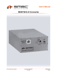
MediaLB Monitor USB
Active-Pod MediaLB 3-Pin LS
Active-Pod MediaLB 3-Pin HS
Active-Pod MediaLB 6-Pin HS
UM_MediaLB_Analyzer_V02_00_XX-3
Mar. 2010
MOST®
Media Oriented Systems Transport
Multimedia and Control
Networking Technology
Copyright © 2008 - 2010 SMSC
*X13307*
MediaLB Analyzer
Legend
Copyright © 2008 - 2010 SMSC. All rights reserved.
Please make sure that all information within a document marked as 'Confidential' or 'Restricted Access' is handled
solely in accordance with the agreement pursuant to which it is provided, and is not reproduced or disclosed to others
without the prior written consent of SMSC. The confidential ranking of a document can be found in the footer of every
page. This document supersedes and replaces all information previously supplied. The technical information in this
document loses its validity with the next edition. Although the information is believed to be accurate, no responsibility is
assumed for inaccuracies. Specifications and other documents mentioned in this document are subject to change without notice. SMSC reserves the right to make changes to this document and to the products at any time without notice.
Neither the provision of this information nor the sale of the described products conveys any licenses under any patent
rights or other intellectual property rights of SMSC or others. There are a number of patents and patents pending on
the MOST technology and other technologies. No rights under these patents are conveyed without any specific agreement between the users and the patent owners. The products may contain design defects or errors known as anomalies, including but not necessarily limited to any which may be identified in this document, which may cause the product
to deviate from published descriptions. Anomalies are described in errata sheets available upon request. SMSC products are not designed, intended, authorized or warranted for use in any life support or other application where product
failure could cause or contribute to personal injury or severe property damage. Any and all such uses without prior written approval of an officer of SMSC will be fully at your own risk. MediaLB, SMSC and MOST are registered trademarks
of Standard Microsystems Corporation ("SMSC") or its subsidiaries. Other names mentioned may be trademarks of
their respective holders.
SMSC disclaims and excludes any and all warranties, including without limitation any and all implied warranties of merchantability, fitness for a particular purpose, title, and against infringement and the like, and any and all warranties arising from any course of dealing or usage of trade. In no event shall SMSC be liable for any direct, incidental, indirect,
special, punitive, or consequential damages; or for lost data, profits, savings or revenues of any kind; regardless of the
form of action, whether based on contract; tort; negligence of SMSC or others; strict liability; breach of warranty; or otherwise; whether or not any remedy of buyer is held to have failed of its essential purpose, and whether or not SMSC
has been advised of the possibility of such damages.
User Manual
Page 2
Copyright © 2008 - 2010 SMSC
UM_MediaLB_Analyzer_V02_00_XX-3
MediaLB Analyzer
User Manual Versions
Doc. Number
UM_MediaLB_Analyzer_V02_00_XX-3
UM_MediaLB_Analyzer_Hardware_Manual_
V02_00_XX-2
UM_MediaLB_Analyzer_Hardware_Manual_
V02_00_XX-1
User Manual
Date
Mar. 2010
Description
Third Release of User’s Manual
Dec. 2008
Second Release of User’s Manual
June 2008
First Release of User’s Manual
Copyright © 2008 - 2010 SMSC
UM_MediaLB_Analyzer_V02_00_XX-3
Page 3
MediaLB Analyzer
User Manual
Page 4
Copyright © 2008 - 2010 SMSC
UM_MediaLB_Analyzer_V02_00_XX-3
MediaLB Analyzer
TABLE OF CONTENTS
1 PREFACE .................................................................................................................... 9
1.1 Intended Use .................................................................................................................................... 9
1.2 Information Sources ......................................................................................................................... 9
1.3 Terms and Definitions ...................................................................................................................... 9
2 INTRODUCTION ....................................................................................................... 10
2.1 Features ......................................................................................................................................... 11
2.2 Scope of Delivery ........................................................................................................................... 11
3 MEDIALB MONITOR ................................................................................................. 12
3.1 Front Panel ..................................................................................................................................... 12
3.1.1 High-Speed Trigger ................................................................................................................ 12
3.1.2 Trigger .................................................................................................................................... 13
3.1.3 Ready LED ............................................................................................................................. 13
3.1.4 Lock LED ................................................................................................................................ 14
3.1.5 MediaLB Speed ...................................................................................................................... 14
3.1.6 Active-Pod Connector ............................................................................................................ 14
3.2 Rear Panel ..................................................................................................................................... 15
3.2.1 Line Out .................................................................................................................................. 15
3.2.2 S/PDIF Out ............................................................................................................................. 15
3.2.3 USB 2.0 Hi-Speed Connector ................................................................................................ 15
3.2.4 Power Supply ......................................................................................................................... 16
3.3 Specifications ................................................................................................................................. 17
3.3.1 Absolute Maximum Ratings ................................................................................................... 17
3.3.2 Recommended Operating Conditions .................................................................................... 17
3.3.3 DC Characteristics ................................................................................................................. 17
3.3.4 Mechanical Characteristics .................................................................................................... 17
4 ACTIVE-PODS .......................................................................................................... 18
4.1 Active-Pod MediaLB 3-Pin LS ....................................................................................................... 18
4.1.1 MediaLB Connector A and MediaLB Connector B Pin-Out ....................................................19
4.1.2 Status LED ............................................................................................................................. 19
4.1.3 Specifications ......................................................................................................................... 20
4.1.3.1 Absolute Maximum Ratings ........................................................................................... 20
4.1.3.2 Recommended Operating Conditions ............................................................................ 20
4.1.3.3 DC Characteristics ......................................................................................................... 20
4.1.3.4 Mechanical Characteristics ............................................................................................20
4.2 Active-Pod MediaLB 3-Pin HS ....................................................................................................... 21
4.2.1 MediaLB Connector Pin-Out .................................................................................................. 22
4.2.2 Specifications ......................................................................................................................... 23
4.2.2.1 Absolute Maximum Ratings ........................................................................................... 23
4.2.2.2 Recommended Operating Conditions ............................................................................ 23
4.2.2.3 DC Characteristics ........................................................................................................ 23
4.2.2.4 Mechanical Characteristics ............................................................................................23
4.3 Active-Pod MediaLB 6-Pin HS ....................................................................................................... 24
4.3.1 MediaLB Connector Pin-Out .................................................................................................. 25
4.3.2 Specifications ......................................................................................................................... 26
4.3.2.1 Absolute Maximum Ratings ........................................................................................... 26
4.3.2.2 Recommended Operating Conditions ............................................................................ 26
User Manual
Copyright © 2008 - 2010 SMSC
UM_MediaLB_Analyzer_V02_00_XX-3
Page 5
MediaLB Analyzer
4.3.2.3 DC Characteristics ......................................................................................................... 26
4.3.2.4 Mechanical Characteristics ............................................................................................26
User Manual
Page 6
Copyright © 2008 - 2010 SMSC
UM_MediaLB_Analyzer_V02_00_XX-3
MediaLB Analyzer
LIST OF FIGURES
Figure 2-1:
Figure 3-1:
Figure 3-2:
Figure 3-3:
Figure 3-4:
Figure 4-1:
Figure 4-2:
Figure 4-3:
Figure 4-4:
Figure 4-5:
Figure 4-6:
Figure 4-7:
User Manual
MediaLB Analyzer Setup ....................................................................................................... 10
MediaLB Monitor—Front Panel ............................................................................................. 12
MediaLB Monitor—High-Speed Trigger Characteristics ........................................................ 12
MediaLB Monitor—Rear Panel ..............................................................................................15
MediaLB Monitor—Power Connector (Rear Panel) ............................................................... 16
Active-Pod MediaLB 3-Pin LS—Connectors and Status LED ............................................... 18
Active-Pod MediaLB 3-Pin HS—Active-Pod Connector ........................................................ 21
Active-Pod MediaLB 3-Pin HS—MediaLB Connector ........................................................... 21
Active-Pod MediaLB 3-Pin HS—Pin-Out MediaLB Connector .............................................. 22
Active-Pod MediaLB 6-Pin HS—Active-Pod Connector ........................................................ 24
Active-Pod MediaLB 6-Pin HS—MediaLB Connector ........................................................... 24
Active-Pod MediaLB 6-Pin HS—Pin-Out MediaLB Connector .............................................. 25
Copyright © 2008 - 2010 SMSC
UM_MediaLB_Analyzer_V02_00_XX-3
Page 7
MediaLB Analyzer
LIST OF TABLES
Table 1-1:
Table 3-1:
Table 3-2:
Table 3-3:
Table 3-4:
Table 3-5:
Table 3-6:
Table 3-7:
Table 3-8:
Table 3-9:
Table 4-1:
Table 4-2:
Table 4-3:
Table 4-4:
Table 4-5:
Table 4-6:
Table 4-7:
Table 4-8:
Table 4-9:
Table 4-10:
Table 4-11:
User Manual
Page 8
Terms and Definitions .............................................................................................................. 9
MediaLB Monitor—Ready LED..............................................................................................13
MediaLB Monitor—Red Ready LED Blinks Continuously...................................................... 13
MediaLB Monitor—Red Ready LED ...................................................................................... 13
MediaLB Monitor—Lock LED ................................................................................................ 14
MediaLB Monitor—MediaLB Speed ...................................................................................... 14
MediaLB Monitor—Pin Assignment of Power Supply Connector .......................................... 16
MediaLB Monitor—Absolute Maximum Ratings .................................................................... 17
MediaLB Monitor—Recommended Operating Conditions ..................................................... 17
MediaLB Monitor—DC Characteristics .................................................................................. 17
Active-Pod MediaLB 3-Pin LS—Connector A & B Pin-Out ....................................................19
Active-Pod MediaLB 3-Pin LS—Status LED Interpretation ................................................... 19
Active-Pod MediaLB 3-Pin LS—Absolute Maximum Ratings ................................................ 20
Active-Pod MediaLB 3-Pin LS—Recommended Operating Conditions................................. 20
Active-Pod MediaLB 3-Pin LS—DC Characteristics .............................................................. 20
Active-Pod MediaLB 3-Pin HS—Absolute Maximum Ratings................................................ 23
Active-Pod MediaLB 3-Pin HS—Recommended Operating Conditions ................................ 23
Active-Pod MediaLB 3-Pin HS—DC Characteristics ............................................................. 23
Active-Pod MediaLB 6-Pin HS—Absolute Maximum Ratings................................................ 26
Active-Pod MediaLB 6-Pin HS—Recommended Operating Conditions ................................ 26
Active-Pod MediaLB 6-Pin HS—DC Characteristics ............................................................. 26
Copyright © 2008 - 2010 SMSC
UM_MediaLB_Analyzer_V02_00_XX-3
MediaLB Analyzer
1 Preface
1.1 Intended Use
This SMSC product is intended to be used for developing, testing or analyzing MediaLB and MOST based
multimedia products and systems by persons with experience in developing multimedia devices.
The operation of this SMSC product is only admitted with original SMSC devices, e.g., provided power
supply.
Do not interfere in the product's original state, otherwise user safety, faultless operation and electromagnetic compatibility is not guaranteed.
1.2 Information Sources
•
MediaLB Analyzer User Manual (this document):
Describes the MediaLB Monitor and the MediaLB Active-Pods
•
OptoLyzer Suite Start-up Guide [1]:
Describes in a brief manner how to connect the hardware components of the MediaLB Analyzer and
how to install the OptoLyzer Suite supporting MediaLB signal/data analysis and verification
•
OptoLyzer Suite Online Help [2]:
Describes the software usage in detail
•
Media Local Bus Specification [3]:
Defines the MediaLB Physical-Layer and Link-Layer Protocol
1.3 Terms and Definitions
For better understanding of the following sections, the table below explains special terms used within this
user manual.
Term
Active-Pod
DUT
INIC
LED
LVTTL
MediaLB
MediaLB Monitor
S/PDIF
Trigger
Definition
Part of the MediaLB Analyzer. It is a small housing that is directly connected to the MediaLB
Debug Header of the DUT. It buffers the MediaLB signals and transfers them to the MediaLB
Monitor.
Device Under Test
Intelligent Network Interface Controller
Light Emitting Diode
Low Voltage Transistor to Transistor Logic
Media Local Bus
Part of the MediaLB Analyzer. It formats, processes and buffers the incoming serial data
before feeding it via USB to the Host PC.
Sony Philips Digital Interface
A hardware trigger defines when to capture data from MediaLB.
Table 1-1: Terms and Definitions
User Manual
Copyright © 2008 - 2010 SMSC
UM_MediaLB_Analyzer_V02_00_XX-3
Page 9
MediaLB Analyzer
2 Introduction
MediaLB Analyzer is a tool defined by a combination of hardware and software components designed to
observe and visualize MediaLB data in a comfortable way.
MediaLB Analyzer consists of the following main modules:
Hardware Modules
• MediaLB Monitor USB - converter box transferring MediaLB data received from the Active-Pods via
USB 2.0 to a Host PC (described in Chapter 3). It represents a package of the MediaLB Monitor (3)
converter box, cables required to setup a MediaLB Analyzer, power supply and user manual.
• Active-Pods (2) - functioning as interface to the MediaLB port of the Device Under Test (1) (described in
Chapter 4)
Software Module
• OptoLyzer Suite (6) - software, which supports analysis and visualization of MediaLB data (see separate OptoLyzer Suite documentation for details). OptoLyzer Suite is running on a Host PC/laptop (5).
The USB connector on the PC has to be a USB 2.0 Hi-Speed connector (4).
OptoLyzer Suite with
MediaLB Support (6)
Active-Pod
MediaLB
3/6-Pin (2)
USB 2.0 Hi-Speed
Port (4)
MediaLB Monitor (3)
Host PC/Laptop (5)
DUT (1)
Short Cable Connection
USB 2.0
Cable Connection
Figure 2-1: MediaLB Analyzer Setup
All components of the MediaLB Analyzer including the MediaLB Monitor USB, the Active-Pods and the
OptoLyzer Suite software need to be purchased to complete a MediaLB Analyzer setup. Active-Pods have
to be purchased dependent on the MediaLB interface (3-Pin or 6-Pin) to be analyzed and the MediaLB
Debug Header connector (LS or HS) used.
User Manual
Page 10
Copyright © 2008 - 2010 SMSC
UM_MediaLB_Analyzer_V02_00_XX-3
MediaLB Analyzer
2.1 Features
The MediaLB Analyzer hardware modules provide the following features:
• MediaLB Monitor
• Streaming capable USB 2.0 Hi-Speed interface
• MediaLB Clock-Activity, Speed and Lock detection
• 256 MByte RAM for data buffering
• Compact housing
• High-speed trigger input
• Active-Pods
• Active-Pod MediaLB 3-Pin LS
- Support for OS81050/OS81082/OS81110 LS MediaLB Debug Header
- Support for MediaLB 3-Pin interfaces up to and including 1024Fs
• Active-Pod MediaLB 3-Pin HS
- Support for OS81050/OS81082/OS81110 HS MediaLB Debug Header
- Support for MediaLB 3-Pin interfaces up to and including 1024Fs
• Active-Pod MediaLB 6-Pin HS
- Support for OS81110 HS MediaLB Debug Header
- Support for MediaLB 6-Pin interfaces up to and including 8192Fs
2.2 Scope of Delivery
The MediaLB Monitor USB is delivered with:
•
•
•
•
MediaLB Monitor
Power supply
Cables (USB, Active-Pod)
MediaLB Analyzer User Manual (this document)
Dependent on the Active-Pod required, the package can contain one of the below listed parts:
• Active-Pod MediaLB 3-Pin LS
• Active-Pod MediaLB 3-Pin HS
• Active-Pod MediaLB 6-Pin HS
Check your shipment for completeness.
If you have any complaints direct them to [email protected] (Europe and Asia) or to
[email protected] (America). Providing the delivery note number eases the handling.
User Manual
Copyright © 2008 - 2010 SMSC
UM_MediaLB_Analyzer_V02_00_XX-3
Page 11
MediaLB Analyzer
3 MediaLB Monitor
The MediaLB Monitor formats, processes and buffers the incoming serial data before feeding it via USB to
the Host PC.
Ready
Trigger
High Speed
Trigger
Lock
3.1 Front Panel
MediaLB Speed
Active Pod
Figure 3-1: MediaLB Monitor—Front Panel
3.1.1 High-Speed Trigger
High-speed trigger connector is an SMA jack type connector accepting an LVTTL-compatible input. It can
be used to trigger on external events. The trigger event is generated upon the transition of logical low-level
to logical high-level. For details about characteristic values refer to Section 3.3.3 on page 17.
V
Vh
Vl
1
0
t
Vh = Vhigh
Vl = Vlow
tx = Trigger uncertainty
tx
Figure 3-2: MediaLB Monitor—High-Speed Trigger Characteristics
User Manual
Page 12
Copyright © 2008 - 2010 SMSC
UM_MediaLB_Analyzer_V02_00_XX-3
MediaLB Analyzer
3.1.2 Trigger
Will be activated in a later version of MediaLB Monitor.
3.1.3 Ready LED
Color of LED
Green
Status
On
Shortly
Blinking
Continuously
Red
On
Description
Indicates the MediaLB Monitor is powered and
ready for operation.
Indicates the MediaLB Monitor is booting.
Indicates booting cannot be completed. Refer to:
Possible reasons for a red Ready LED that is blinking continuously:
Indicates an error is occurred. Refer to:
Possible reasons for a red Ready LED:
Table 3-1: MediaLB Monitor—Ready LED
Possible reasons for a red Ready LED that is blinking continuously:
Reason
OptoLyzer Suite is not yet started.
MediaLB Monitor device is not yet added in the
OptoLyzer Suite.
Action
Start OptoLyzer Suite.
Add MediaLB Monitor device. Refer to the online help of the
OptoLyzer Suite for details.
Table 3-2: MediaLB Monitor—Red Ready LED Blinks Continuously
Possible reasons for a red Ready LED:
Reason
If the PC runs too slow for processing all
MediaLB data, the buffer eventually will get an
overflow. This can occur after some seconds to
minutes (depending on the transmitted load).
Action
Set the ‘Memory Depth’ on tab ‘License/Memory/MOST Speed’ to
100000 (default).
Use dedicated filters to focus only on the data of interest.
Check the PC system requirements. Refer to the OptoLyzer Suite’s
online help.
User stops streaming of data by clicking the Stop
Click the Run button of the MediaLB Monitor device in the
button of the MediaLB Monitor device in the
OptoLyzer Suite.
OptoLyzer Suite.
MediaLB Monitor USB driver is not installed or
Consider reinstallation of the OptoLyzer Suite.
not loaded properly.
Table 3-3: MediaLB Monitor—Red Ready LED
User Manual
Copyright © 2008 - 2010 SMSC
UM_MediaLB_Analyzer_V02_00_XX-3
Page 13
MediaLB Analyzer
3.1.4 Lock LED
Color of LED
Description
Indicates a MediaLB lock state
Indicates there is no MediaLB lock but toggling (activity) of
MediaLB clock pin.
Indicates there is no MediaLB lock and no toggling (activity) of
MediaLB clock pin.
Green
Red
Dark
Table 3-4: MediaLB Monitor—Lock LED
3.1.5 MediaLB Speed
The yellow LEDs indicate the MediaLB speed. In the table below they are listed from left to right.
‘z’ means LED is off, ‘’ means LED is on.
MediaLB Speed
LEDs
Fs
256, only if Lock LED is on
512
1024
2048
3072
4096
6144
8192
zzz
zz
zz
z
zz
z
z
Table 3-5: MediaLB Monitor—MediaLB Speed
3.1.6 Active-Pod Connector
The Active-Pod connector has to be connected to the respective Active-Pod using the Active-Pod cable.
User Manual
Page 14
Copyright © 2008 - 2010 SMSC
UM_MediaLB_Analyzer_V02_00_XX-3
MediaLB Analyzer
3.2 Rear Panel
S/PDIF
Out
USB 2.0
Hi-Speed
Power
Supply
Line
Out
Figure 3-3: MediaLB Monitor—Rear Panel
3.2.1 Line Out
Will be activated in a later version of MediaLB Monitor.
3.2.2 S/PDIF Out
Will be activated in a later version of MediaLB Monitor.
3.2.3 USB 2.0 Hi-Speed Connector
Type: USB type B connector
Notice
User Manual
It is mandatory to connect this connector with a USB 2.0 Hi-Speed connector on
the PC! Check, if a USB connector of your PC system provides USB 2.0 Hi-Speed
capability. If so, the Device Manager will show an Enhanced USB Host Controller
for this connector.
Copyright © 2008 - 2010 SMSC
UM_MediaLB_Analyzer_V02_00_XX-3
Page 15
MediaLB Analyzer
3.2.4 Power Supply
Type: Binder, serial 718
3
2
1
Figure 3-4: MediaLB Monitor—Power Connector (Rear Panel)
The table shows the pin assignment of the power connector.
Pin
1
2
3
Description
Power
Reserved
GND
Table 3-6: MediaLB Monitor—Pin Assignment of Power Supply Connector
User Manual
Page 16
Copyright © 2008 - 2010 SMSC
UM_MediaLB_Analyzer_V02_00_XX-3
MediaLB Analyzer
3.3 Specifications
3.3.1 Absolute Maximum Ratings
Parameter
Power supply voltage
MediaLB signal voltage
Operating (ambient) temperature
Storage temperature
Min.
-0.4
-0.4
0
-20
Max.
25
3.7
40
85
Unit
V
V
°C
°C
Max.
-
Unit
°C
V
Table 3-7: MediaLB Monitor—Absolute Maximum Ratings
3.3.2 Recommended Operating Conditions
Parameter
Operating (ambient) temperature
Power supply
Min.
-
Typ.
21
12
Table 3-8: MediaLB Monitor—Recommended Operating Conditions
3.3.3 DC Characteristics
Parameter
Power consumption
High-speed Trigger input voltage: low
High-speed Trigger input voltage: high
High-speed Trigger input capacitance
Line out (RLoad)
High-speed Trigger output voltage (high/lowlevel)
Condition
Power supply voltage = 12 V
Min.
50
0
2
-
Typ.
150
20
Max.
300
0.8
3.3
-
Unit
mA
V
V
pF
Will be activated in a later version of MediaLB Monitor.
Table 3-9: MediaLB Monitor—DC Characteristics
3.3.4 Mechanical Characteristics
Protection Rating:
Dimensions:
User Manual
IP 42
MediaLB Monitor:
USB cable:
Active-Pod cable:
Copyright © 2008 - 2010 SMSC
113 / 82 / 32 mm (l / w / h)
1m
40 cm
UM_MediaLB_Analyzer_V02_00_XX-3
Page 17
MediaLB Analyzer
4 Active-Pods
An Active-Pod is a small device that is directly connected to the MediaLB Debug Header of the DUT. It buffers the MediaLB signals and transfers them to the MediaLB Monitor without compromising the signal
integrity.
4.1 Active-Pod MediaLB 3-Pin LS
An Active-Pod MediaLB 3-Pin LS has three connectors: Two MediaLB connectors (MediaLB Connector A
and MediaLB Connector B), which are used to connect the Active-Pod to the MediaLB on the DUT and one
Active-Pod Connector, which is used to connect the Active-Pod by means of a special cable to the
MediaLB Monitor. Note, the cable is part of the MediaLB Monitor USB delivery.
MediaLB Connector A is a 10-pin male type, 2 mm pitch connector. It is placed on the front side of the
Active-Pod. This connector is used to connect the Active-Pod by means of an extension connector to the
DUT.
MediaLB Connector B is a 10-pin female type, 2 mm pitch connector placed on the bottom side of the
Active-Pod. This connector is used to connect the Active-Pod directly (or by means of an extension connector) on the dedicated connector on the DUT.
Status LED
Status LED
Active-Pod
Connector
MediaLB Connector A
Pin 1
Front View
Rear View
MediaLB Connector B
Pin 1
MediaLB
Connector A
Bottom View
Figure 4-1: Active-Pod MediaLB 3-Pin LS—Connectors and Status LED
User Manual
Page 18
Copyright © 2008 - 2010 SMSC
UM_MediaLB_Analyzer_V02_00_XX-3
MediaLB Analyzer
4.1.1 MediaLB Connector A and MediaLB Connector B Pin-Out
MediaLB Connectors A and B are electrically one-to-one interconnected, so that the corresponding pins
have the same functionality (pin 1 of MediaLB Connector A Ù pin 1 of MediaLB Connector B).
GND
Pin 2
MLBCK
Pin 1
GND
Pin 4
MLBSIG
Pin 3
DUT
Detection*)
Pin 6
MLBDAT
Pin 5
Pin 8
n.c.
Pin 7
Pin 10
n.c.
Pin 9
GND
All pins are inputs (except GND) and are named according to the corresponding
pins of the MediaLB Debug Header.
GND
Notice
*) On DUT this pin has to be connected to GND.
Table 4-1: Active-Pod MediaLB 3-Pin LS—Connector A & B Pin-Out
4.1.2 Status LED
The following table gives an overview of the possible LED states.
Status LED
Dark
Red
Yellow
Green
Description
MediaLB Monitor is not connected to the Active-Pod.
MediaLB Monitor has no power.
MediaLB Monitor has no connection to MediaLB.
The DUT detection pin* on the DUT is not connected to
ground.
MediaLB connector A or B is connected properly to
MediaLB, but the MediaLB provides no clock signal.
MediaLB clock is present.
Action
Check the connection.
Check the power supply/USB.
Check the connection.
Check the pin assignment of the
detection pin.
Make sure, MediaLB is initialized and
running.
Normal operation
* Since the DUT detection pin detects the connection to MediaLB, it is important that pin 5 of the DUT is connected to
ground.
Table 4-2: Active-Pod MediaLB 3-Pin LS—Status LED Interpretation
User Manual
Copyright © 2008 - 2010 SMSC
UM_MediaLB_Analyzer_V02_00_XX-3
Page 19
MediaLB Analyzer
4.1.3 Specifications
4.1.3.1 Absolute Maximum Ratings
Parameter
MediaLB signal voltage
Operating (ambient) temperature
Storage temperature
Min.
-0.4
0
-20
Max.
3.7
40
85
Unit
V
°C
°C
Table 4-3: Active-Pod MediaLB 3-Pin LS—Absolute Maximum Ratings
4.1.3.2 Recommended Operating Conditions
Parameter
Operating (ambient) temperature
Min.
-
Typ.
21
Max.
-
Unit
°C
Table 4-4: Active-Pod MediaLB 3-Pin LS—Recommended Operating Conditions
4.1.3.3 DC Characteristics
Parameter
Input resistance
Input capacitance
Input high voltage
Input low voltage
Min.
100
Typ.
-
Max.
-
Unit
kΩ
5
6
10
pF
1.70
-
3.6
V
-0.3
-
0.70
V
Table 4-5: Active-Pod MediaLB 3-Pin LS—DC Characteristics
4.1.3.4 Mechanical Characteristics
• Protection Rating:
• Dimensions:
User Manual
Page 20
IP 42
Active-Pod:
Active-Pod cable:
56 / 37 / 25 mm (l / w / h)
40 cm
Copyright © 2008 - 2010 SMSC
UM_MediaLB_Analyzer_V02_00_XX-3
MediaLB Analyzer
4.2 Active-Pod MediaLB 3-Pin HS
An Active-Pod MediaLB 3-Pin HS has two connectors: one MediaLB Connector, which is used for connecting the Active-Pod to the MediaLB on the DUT and one Active-Pod Connector, which is used to connect
the Active-Pod by means of a special cable to the MediaLB Monitor. The cable is part of the MediaLB Monitor USB delivery.
Figure 4-2: Active-Pod MediaLB 3-Pin HS—Active-Pod Connector
Pin 1 Pin 3
GND
Pin 2 Pin 4
Figure 4-3: Active-Pod MediaLB 3-Pin HS—MediaLB Connector
User Manual
Copyright © 2008 - 2010 SMSC
UM_MediaLB_Analyzer_V02_00_XX-3
Page 21
MediaLB Analyzer
4.2.1 MediaLB Connector Pin-Out
The MediaLB Connector of type QTH-020-01-L-D-DP-A (Samtec) is a 40-pin connector having a GND
stripe in the middle. It is placed on the front side of the Active-Pod. This connector is used for connecting
the Active-Pod by means of an extension connector to the DUT.
Pin 27
Pin 29
Pin 31
Pin 33
Pin 35
Pin 37
Pin 39
Pin 28
Pin 30
Pin 32
Pin 34
Pin 36
Pin 38
Pin 40
DUT
Detection*)
DUT
Detection*)
Pin 25
Pin 26
n.c.**)
Pin 23
Pin 24
Pin 21
Pin 19
Pin 17
Pin 15
Pin 13
Pin 11
Pin 9
Pin 7
Pin 5
Pin 3
Pin 1
n.c.**)
The DUT connector should be of type QSH-020-01-L-D-DP-A (Samtec).
Pin 22
Pin 20
Pin 18
Pin 16
Pin 14
Pin 12
Pin 10
MLBDAT
Pin 8
Pin 4
Pin 6
MLBSIG
MLBCK
Pin 2
GND
*) On DUT this pin has to be connected to 3.3 VCC.
**) For future use. Do not connect these pins.
Figure 4-4: Active-Pod MediaLB 3-Pin HS—Pin-Out MediaLB Connector
User Manual
Page 22
Copyright © 2008 - 2010 SMSC
UM_MediaLB_Analyzer_V02_00_XX-3
MediaLB Analyzer
4.2.2 Specifications
4.2.2.1 Absolute Maximum Ratings
Parameter
MediaLB signal voltage
Operating (ambient) temperature
Storage temperature
Min.
-0.4
0
-20
Max.
3.7
40
85
Unit
V
°C
°C
Table 4-6: Active-Pod MediaLB 3-Pin HS—Absolute Maximum Ratings
4.2.2.2 Recommended Operating Conditions
Parameter
Operating (ambient) temperature
Min.
-
Typ.
21
Max.
-
Unit
°C
Table 4-7: Active-Pod MediaLB 3-Pin HS—Recommended Operating Conditions
4.2.2.3 DC Characteristics
Parameter
Min.
100
5
2
-0.15
Input resistance
Input capacitance
Input high voltage
Input low voltage
Typ.
6
-
Max.
10
3.45
0.8
Unit
kΩ
pF
V
V
Table 4-8: Active-Pod MediaLB 3-Pin HS—DC Characteristics
4.2.2.4 Mechanical Characteristics
• Protection Rating:
• Dimensions:
User Manual
IP 42
Active-Pod:
Active-Pod cable:
35 / 22 / 8 mm (l / w / h)
40 cm
Copyright © 2008 - 2010 SMSC
UM_MediaLB_Analyzer_V02_00_XX-3
Page 23
MediaLB Analyzer
4.3 Active-Pod MediaLB 6-Pin HS
An Active-Pod MediaLB 6-Pin HS has two connectors: one MediaLB Connector, which is used for connecting the Active-Pod to the MediaLB on the DUT and one Active-Pod Connector, which is used to connect
the Active-Pod by means of a special cable to the MediaLB Monitor. The cable is part of the MediaLB Monitor USB delivery.
Figure 4-5: Active-Pod MediaLB 6-Pin HS—Active-Pod Connector
Pin 1 Pin 3
GND
Pin 2 Pin 4
Figure 4-6: Active-Pod MediaLB 6-Pin HS—MediaLB Connector
User Manual
Page 24
Copyright © 2008 - 2010 SMSC
UM_MediaLB_Analyzer_V02_00_XX-3
MediaLB Analyzer
4.3.1 MediaLB Connector Pin-Out
The MediaLB Connector of type QTH-020-01-L-D-DP-A (Samtec) is a 40-pin connector having a GND
stripe in the middle. It is placed on the front side of the Active-Pod. This connector is used for connecting
the Active-Pod by means of an extension connector to the DUT.
Pin 25
Pin 27
Pin 29
Pin 31
Pin 33
Pin 35
Pin 37
Pin 39
Pin 26
Pin 28
Pin 30
Pin 32
Pin 34
Pin 36
Pin 38
Pin 40
DUT
Detection*)
Pin 23
Pin 24
MLBCKP
Pin 19
Pin 21
MLBCKN
Pin 17
Pin 15
MLBDP
Pin 11
Pin 13
MLBDN
Pin 9
Pin 7
MLBSP
Pin 3
Pin 5
MLBSN
Pin 1
The DUT connector should be of type QSH-020-01-L-D-DP-A (Samtec).
Pin 22
Pin 20
Pin 18
Pin 16
Pin 14
Pin 12
Pin 10
Pin 8
Pin 6
Pin 4
Pin 2
GND
*) On DUT this pin has to be connected to 3.3 VCC.
Figure 4-7: Active-Pod MediaLB 6-Pin HS—Pin-Out MediaLB Connector
User Manual
Copyright © 2008 - 2010 SMSC
UM_MediaLB_Analyzer_V02_00_XX-3
Page 25
MediaLB Analyzer
4.3.2 Specifications
4.3.2.1 Absolute Maximum Ratings
Parameter
MediaLB signal voltage
Operating (ambient) temperature
Storage temperature
Min.
-0.4
0
-20
Max.
3.7
40
85
Unit
V
°C
°C
Table 4-9: Active-Pod MediaLB 6-Pin HS—Absolute Maximum Ratings
4.3.2.2 Recommended Operating Conditions
Parameter
Operating (ambient) temperature
Min.
-
Typ.
21
Max.
-
Unit
°C
Table 4-10: Active-Pod MediaLB 6-Pin HS—Recommended Operating Conditions
4.3.2.3 DC Characteristics
Parameter
Min.
50
3
0.05
-
Input resistance
Input capacitance
Input common voltage
Input differential threshold
Typ.
5
±7
Max.
8
2.35
±50
Unit
kΩ
pF
V
mV
Table 4-11: Active-Pod MediaLB 6-Pin HS—DC Characteristics
4.3.2.4 Mechanical Characteristics
• Protection Rating:
• Dimensions:
User Manual
Page 26
IP 42
Active-Pod:
Active-Pod cable:
35 / 22 / 85 mm (l / w / h)
40 cm
Copyright © 2008 - 2010 SMSC
UM_MediaLB_Analyzer_V02_00_XX-3
MediaLB Analyzer
Appendix A: Index
A
Active-Pod ..............................................................................................................................................................9, 18
Active-Pod Connector ...............................................................................................................................................14
Active-Pod MediaLB 3-Pin HS ................................................................................................................................21
Active-Pod MediaLB 3-Pin LS .................................................................................................................................18
Active-Pod MediaLB 6-Pin HS ................................................................................................................................24
D
Definitions of Terms .....................................................................................................................................................9
DUT ...............................................................................................................................................................................9
E
Enhanced USB ..........................................................................................................................................................15
F
Front Panel .................................................................................................................................................................12
H
High-Speed Trigger ...................................................................................................................................................12
I
INIC ................................................................................................................................................................................9
Intended Use ................................................................................................................................................................9
L
LED ................................................................................................................................................................................9
Lock ..........................................................................................................................................................................14
MediaLB Speed .......................................................................................................................................................14
Ready .......................................................................................................................................................................13
Status ........................................................................................................................................................................19
Line Out .......................................................................................................................................................................15
Lock LED ....................................................................................................................................................................14
LVTTL ............................................................................................................................................................................9
M
MediaLB ........................................................................................................................................................................9
MediaLB Connector A ...............................................................................................................................................18
MediaLB Connector B ...............................................................................................................................................18
MediaLB Monitor .........................................................................................................................................................9
MediaLB Speed .........................................................................................................................................................14
MediaLB Speed LED .................................................................................................................................................14
P
Pin-Out, Active-Pod MediaLB 3-Pin HS .................................................................................................................22
Pin-Out, Active-Pod MediaLB 3-Pin LS .................................................................................................................19
Pin-Out, Active-Pod MediaLB 6-Pin HS .................................................................................................................25
Pin-Out, MediaLB Connector ...................................................................................................................................22
Pin-Out, MediaLB Connector A ...............................................................................................................................19
Pin-Out, MediaLB Connector B ...............................................................................................................................19
Q
QSH-020-01-L-D-DP-A (Samtec) .....................................................................................................................22, 25
QTH-020-01-L-D-DP-A (Samtec) .....................................................................................................................22, 25
User Manual
Copyright © 2008 - 2010 SMSC
UM_MediaLB_Analyzer_V02_00_XX-3
Page 27
MediaLB Analyzer
R
Ready LED .................................................................................................................................................................13
Rear Panel ..................................................................................................................................................................15
S
S/PDIF ...........................................................................................................................................................................9
S/PDIF Out .................................................................................................................................................................15
Samtec, QSH-020-01-L-D-DP-A .......................................................................................................................22, 25
Samtec, QTH-020-01-L-D-DP-A .......................................................................................................................22, 25
Status LED ..................................................................................................................................................................19
T
Term Definitions ...........................................................................................................................................................9
Trigger .....................................................................................................................................................................9, 13
U
USB 2.0 Hi-Speed Connector ..................................................................................................................................15
User Manual
Page 28
Copyright © 2008 - 2010 SMSC
UM_MediaLB_Analyzer_V02_00_XX-3
MediaLB Analyzer
Appendix B: Revision History
Version
Date
UM_MediaLB_Analyzer_V02_00_XX-3
Mar. 2010
UM_MediaLB_Analyzer_Hardware
_Manual_V02_00_XX-2
Dec. 2008
UM_MediaLB_Analyzer_Hardware
_Manual_V02_00_XX-1
June 2008
User Manual
Section
General
Section 4.2
All
Section 4.3
-
Description of Changes
Reworked document
Active-Pod MediaLB 3-Pin HS: Added new
section
Reworked document:
Active-Pod MediaLB 6-Pin HS: Added new
section
First version
Copyright © 2008 - 2010 SMSC
UM_MediaLB_Analyzer_V02_00_XX-3
Page 29
MediaLB Analyzer
Notes:
User Manual
Page 30
Copyright © 2008 - 2010 SMSC
UM_MediaLB_Analyzer_V02_00_XX-3
MediaLB Analyzer
Notes:
User Manual
Copyright © 2008 - 2010 SMSC
UM_MediaLB_Analyzer_V02_00_XX-3
Page 31
Further Information
For more information on SMSC’s automotive products, including integrated circuits, software, and MOST
development tools and modules, visit our web site: http://www.smsc-ais.com. Direct contact information is
available at: http://www.smsc-ais.com/offices.
SMSC Europe GmbH
Bannwaldallee 48
76185 Karlsruhe
GERMANY
SMSC
80 Arkay Drive
Hauppauge, New York 11788
USA
Technical Support
Contact information for technical support is available at: http://www.smsc-ais.com/contact.