1
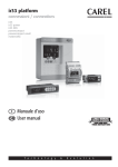
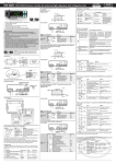
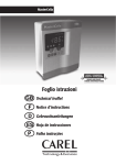
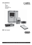
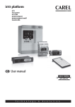
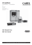
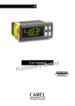
+0500018EN - rel. 3.2 del 01.04.2008
PB00* - powercompact
Models PB00(S,Y,F,C,H)(0,6)(0,E,A,H)(N,R,C,B,A,M,L,T,P,Q,S,U,V,X,Y,Z)(1,2,3,4,5,A,B,C,D,E,F)0
Option codes
NO POWER
& SIGNAL
CABLES
TOGETHER
READ CAREFULLY IN THE TEXT!
WARNING: separate as much as possible the probe and digital input signal
cables from the cables carrying inductive loads and power cables to avoid
possible electromagnetic disturbance. Never run power cables (including the
electrical panel wiring) and signal cables in the same conduits.
CODE
IRTRRES000
IROPZ48500
IROPZ485S0
IROPZDSP00
PST00VR100
IR00RG0000
IR00RR0000
PSTCON01B0
PSTCON03B0
PSTCON05B0
PSOPZKEY00
PSOPZKEYA0
IROPZKEY00
IROPZKEYA0
VPMSTDKY*0
Dimensions (mm)
powercompact:
Display
36
28.2
powercompact uses a built-in display terminal with three LED digits and icon, to display the operating status. An additional display can be connected to the powercompact controller, via a suitable
interface for example to display the reading of a third probe.
64
167
75
Icon
dima di foratura
drilling template
138.5 x 29mm
Function
versione con faston + 8 mm
faston version + 8 mm
COMPRESS.
ON
compressor ON
FAN
fan ON
153.5
AUX
fan OFF
defrost ON
defrost OFF
defrost request
auxiliary output AUX
active
auxiliary output
AUX not active
ALARM
delayed external alarm
(before the expiry of
the time ‘A7’)
no alarm present
anti-sweat heater
function active
alarms in normal
operation (e.g. high/
low temperature) or
alarm from external
digital input, immediate or delayed
CLOCK
if at least 1 timed
defrost has been set
no timed defrost is
clock alarm present
LIGHT
auxiliary output LIGHT
active
auxiliary output
LIGHT not active
anti-sweat heater
function active
malfunction (e.g.
EEPROM error or
probe fault)
HACCP alarm (HA
and/or HF)
8
versione con faston + 8 mm
faston version + 8 mm
153.5
SERVICE
165
36
28,5
dima di foratura
drilling template
71x29mm
Fig. 1
41.7
HACCP function
enabled
CONTINUOUS
CYCLE
CONTINUOUS CYCLE
enabled
HACCP function not
enabled
ON if realtime clock
present
2
Button Pressing the button
alone other
ON/OFF
PRG/
MUTE
powercompact PB wide:
UP/CC
LUCE
AUX
PST00VR100: repeater display interface
2
1
DOWN/
DEF
3
tipo Pozidriv
tipo Pozidriv
Panel mounting:
by two countersunk
screws, max.
diameter 3.9 mm.
NO EXCEDER EN
EL AJUSTE
NÃO EXAGERAR
NO APERTO
max 2.5
SET
Fig. 2
2. Pressing the
on an instrument connected to the network recognises the message sent by the
remote application, automatically sets the address to the desired value and sends a confirmation
message to the application, containing the unit code and firmware revision (message ‘V’). When
the message sent by the remote application is recognised, the instrument shows the message
‘Add’ on the display for 5 seconds, followed by the value of the serial address assigned;
3. The application, on receiving the confirmation message from the units connected to the network,
saves the information received in its database, increases the serial address and sends the message
‘<!ADR>’ again;
4. At this point, the procedure starting from point 2 can be repeated on another unit connected to
the network, until defining all the network addresses.
Pressing together with buttons address
1. Hold the
button for more than 5 s (if there are active alarms, first mute the buzzer), the display
will show the first modifiable “F” parameter.
Modifying the parameters
After having displayed the parameter, either type “C” or type “F”, proceed as follows:
1. Press the
or
button to scroll the parameters, until reaching the parameter to be modified;
when scrolling, an icon appears on the display representing the category the parameter belongs
to.
2. Alternatively, press the
button to display a menu that is used to quickly access the category of
parameters to be modified.
Request
Start-up automatic
assignment
enters the menu to
HACCP display and delete the
HACCP alarms
1
This is a special procedure that, using an application installed on a PC, allows setting and managing
simply the addresses of all instruments (featuring this function) connected to the CAREL network.
The procedure is very simple:
1. Using the remote application. The “Network definition” procedure started; the application sends a
special message (‘<!ADR>’) across the CAREL network, containing the network address.
Accessing the configuration parameters (type F)
CONTINUOUS
CONTINUOUS CYCLE
CYCLE not enabled
request
Normal operation
Icon
Automatic assignment of the serial address
2. Press the
or
button until displaying the number “22” (parameter access password)
3. Confirm by pressing the “set” button.
4. The display shows the code of the first modifiable “C” parameter.
The blinking status indicates a request for activation that cannot be implemented until the end of the
corresponding delay times.
powercompact:
Panel mounting: by two lateral sliding plastic brackets.
buttons;
1. Press the
and “set“ buttons at the same time for more than 5 seconds; the display will show the
number “00” (password prompt).
Buttons on the keypad
Panel mounting
and
button until the message “Std” is shown on the display
Accessing the configuration parameters (type C)
Tab. 2
35
81
no malfunction
HACCP
PST00VR100: repeater display interface
and “Hdn”, using the
4. press the
Start up
fan request
75
dima di foratura
drilling template
da 138.5 a 150 x 31mm
blink
compressor request
AUX
64
183.4
Normal operation
OFF
compressor OFF
DEFROST
28.2
powercompact PB wide:
If “Hdn” < > 0: 1: switch the instrument off; 2: switch the instrument back on, holding the
button until the value 0 is shown on the display; 3: select the set of default parameters, between 0
Note: once the address has been assigned to an instrument, the operation, for safety reasons, is disabled on the
same instrument for 1 minute, preventing a different address from being assigned to the instrument.
Signals on the display
8
39.4
•
DESCRIPTION
small remote control
RS485 serial inteface
RS485 serial board interface with automatic recognition of the polarity +/remote display interface
remote repeater display
remote repeater display ir33 range green display
remote repeater display ir33 range red display
repeater display connection cables 1,5 m
repeater display connection cables 3 m
repeater display connection cables 5 m
parameter programming key with extended memory and 12 V batteries included
parameter programming key with 230 Vac power supply
parameter programming key with 12 V battery included
parameter programming key with extended memory and external 230 Vac power supply
key programming kit
Tab. 1
if pressed for more
than 5 s, switches the
unit on/off
3. Scroll the menu with the
and
buttons; the display shows the codes of the various categories of parameters (see the Summary of operating parameters), accompanied by the display of the
corresponding icon (if present).
4. Once having reached the desired category, press “set” to go directly to the first parameter in the
chosen category (if no parameter is visible, pressing the “set” button will have no effect).
5. At this stage, modify the parameters or return to the “Categories” menu, using the
6. Press “set” to display the value associated with the parameter.
button.
7. Increase or decrease the value using the
or
buttons respectively.
8. Press “set” to temporarily save the new value and return to the display of the parameter.
9. Repeat the operations from point 1 or point 2.
10. If the parameter has sub-parameters, press “set” to display the first sub-parameter.
11. Press the
or
button to display all the sub-parameters.
12. Press “ set” to display the associated value.
if pressed for more
than 5 s, accesses the • SET: if pressed for more than 5 s together
menu for setting type with the SET button accesses the menu
for setting the type “C” (configuration) or
“F” (frequent) parameters in the event
downloading the parameters
of alarm: silences the • UP/CC: if pressed for more than 5 s togeaudible alarm (buzzer) ther with the UP/CC button, resets any
and disables the alarm active alarms with manual reset
relay
• SET: if pressed for more than 5 s together
with the SET button, starts the procedure
if pressed for more
for printing the reports (function available,
than 5 s, enables/
with management to be implemented)
disables continuous
•
PRG/MUTE: if pressed for more than 5 s tocycle operation
gether with the PRG/MUTE button, resets
any active alarms with manual reset
if pressed for more
than 1 s, enables/disables auxiliary AUX2
if pressed for more
than 1 s, enables/disables auxiliary AUX1
if pressed for more
than 5 s, enables/
disables a manual
defrost
• PRG/MUTE: if pressed for more than 5
s together with the PRG/MUTE button
accesses the menu for setting the type
“C” (configuration) or downloading the
if pressed for more
parameters
than 1 s, displays and/
•
UP/CC: if pressed for more than 5 s
or sets the set point
together with the UP/CC button, starts
the procedure for printing the reports
(function available, with management to
be implemented)
if pressed
for more if pressed for
than 5 s at more than 1
start-up,
s, enters the
enables the automatic
procedure serial address
for setting assignment
the default procedure
values
13. Increase or decrease the value using the
or
button respectively.
14. Press “set” to temporarily save the new value and return to the display of the sub-parameter code.
15. Press
to return to the display of the parent parameter.
Saving the new values assigned to the parameters
To definitively save the new values of the modified parameters, press the
button for more than 5
seconds, thus exiting the parameter setting procedure.
All the modifications made to the parameters, temporarily saved in the RAM, can be cancelled and
“normal operation” resumed by not pressing any button for 60 seconds, thus allowing the parameter
setting session to expire due to timeout. If the instrument is switched off before pressing the
button, all the modifications made to the parameters and temporarily saved will be lost.
Directly accessing the parameters by selecting the category
The configuration parameters can also be accessed, in addition to the mode described above, via the
category (see the icons and abbreviations in the table below), according to the list on the display with
the corresponding name and icon. To directly access the list of parameters grouped by category, press
the
button for at least 1 second,
Category
Probe parameters
Control parameters
Compressor parameters
Defrost parameters
Alarm parameters
Fan parameters
Configuration parameters
HACCP parameters
RTC parameters
, and to modify the parameter press “set” ,
Parameters
/
r
c
d
A
F
H
H HACCP
rtc
Message
‘Pro’
‘CtL
‘CMP’
‘dEF’
‘ALM’
‘FAn’
configuration ‘CnF’
‘HcP’
‘rtc’
Icon
Tab. 4
Tab. 3
Wiring diagrams
Probe configuration (/A2.../A5)
Setting the set point (desired temperature value)
PB00C
To display or set the set point, proceed as follows:
1. press the “set” button for more than 1 second to display the set point;
and
2. increase or decrease the value of the set point, using the
reaching the desired value;
3. press the “set” button again to confirm the new value.
Fig. 3
buttons respectively, until
In the powercompact series, this parameter and the model of controller used define the meaning of
the digital input:
and
buttons together for more
3=
As well as the automatic defrost function, a manual defrost can be enabled, if the temperature
for 5 seconds.
conditions allow, by pressing
4=
5=
6=
7=
8=
9=
10 =
11 =
12 =
13 =
14 =
ON/OFF button
Pressing this button for 5 s switches the unit on/off. When the controller is turned off, it actually goes
into standby, and therefore, when carrying out maintenance on the device, it must be disconnected
from the power supply.
HACCP function
Fig. 5
PB00H
Fig. 6
powercompact is compliant with the HACCP standards in force since it allows the monitoring of the
temperature of the stored food. “HA” alarm = exceeded maximum threshold: up to three HA events
are saved (HA, HA1, HA2) respectively from the more recent (HA) to the oldest (HA2) and a HAn signal
that displays the number of occurred HA events. “HF” alarm = power failure lasting over a minute
and exceeded AH maximum threshold: up to three HF events are saved (HF, HF1, HF2) respectively
from the more recent (HF) to the oldest (HF2) and a HFn signal that displays the number of occurred
HF events. HA/HF alarm setting: AH parameter (high temperature threshold); Ad and Htd (Ad+Htd
= HACCP alarm activation delay). Display of the details: access to HA or HF parameters pressing the
or
. buttons to glance over. HACCP alarm erasing: press the “HACCP”
“HACCP” button and use
button for more than 5 s, the message ‘res’ indicates that the alarm have been deleted.To cancel the
saved alarms press the “HACCP” and
buttons for more than 5 s.
PB00S
Continuous cycle
Fig. 7
0=
1=
2=
Manual defrost
Fig. 4
PB00F0H
0 = probe absent; 1 = product probe (used for display only); 2 = defrost probe; 3 = condenser probe;
4 = antifreeze probe.
Configuration of the digital inputs (A4, A5, A9)
Alarms with manual reset
The alarms with manual reset can be reset by pressing the
than 5 s.
PB00F0E
In the powercompact series, these parameters are used to configure the operating mode of the
probes:
Pressing the button
for more than 5 seconds enables the continuous cycle function. During
operation in continuous cycle, the compressor continues to operate for the time ‘cc’ and it stops
when reaches the ‘cc’ time out or the minimum temperature envisaged (AL = minimum temperature
alarm threshold). Continuous cycle setting: “cc” parameter (continuous cycle duration): “cc” = 0 never
active; “c6” parameter (bypassing the alarm after the continuous cycle): it avoids or delays the low
temperature alarm after the continuous cycle.
input not active;
immediate external alarm, normally closed: open = alarm;
delayed external alarm, normally closed;
enable defrost from external contact: open= disabled (an external contact can be connected to the
multifunction input to enable or disable the defrost);
start defrost from external contact;
door switch with stopping of compressor and fans: open = open door;
remote ON/OFF: CLOSED=ON;
curtain switch: close = lowered curtain;
low pressure switch input for pump-down: open = low pressure;
door switch with stopping of fans only: open = open door;
direct/reverse cycle operation: open = direct;
light sensor;
AUX output enabling (if configured with H1 o H5 parameters): opening = enabling;
door switch with compress. and fans OFF, with light not managed;
door switch with fans OFF and light not managed.
Configuration of the relay outputs AUX1 (H1) and AUX2 (H5)
Establishes whether relays AUX1 and AUX2 (present only if envisaged by the model) are used as auxiliary outputs (e.g. demister fan or other ON/OFF actuator), an alarm output, a light output, a defrost
actuator for the auxiliary evaporator, pump-down valve control or output for the condenser fan.
0 = alarm output: normally energised; the relay is de-energised when an alarm occurs;
1 = alarm output: normally de-energised; the relay is energised when an alarm occurs;
2 = auxiliary output;
3 = light output;
4 = auxiliary evaporator defrost output;
5 = pump-down valve output;
6 = condenser fan output;
7 = delayed compressor output;
8 = auxiliary output with OFF shutdown;
9 = light output with OFF shutdown;
10 = disabled output;
11 = reverse output in dead zone control;
12 = second compressor step output;
13 = second compressor step output with rotation.
Warning: the mode H1/H5=0 is useful for signalling the alarm status even in case of power failure.
PB00Y
Procedure for setting the default parameter values
To set the default parameter values on the controller, proceed as follows:
•
5 (4)A
5A 1FLA
6LRA
Fig. 8
If “Hdn” = 0: 1: switch the instrument off; 2: switch the instrument back on, holding the
button until the message “Std” is shown on the display.
Note: the default values are only set for the visible parameters (C and F). For further details see table“Summary of
operating parameters”.
Note: in the models fitted with only one auxiliary output, to associate the button “
” to this output, set H1= 10
and H5= 3. It is necessary to associate the relay assigned to aux 1 to the auxiliary output 2. The operation can be
performed using the programming kit PSOPZPRG00 and the programming key PSOPZKEY00/A0.
IROPZDSP00:
Opzione interfaccia
display
Display interface option
IROPZ485S0:
Interfaccia scheda seriale
RS485 intelligente
Smart serial board
interface RS485
Fig. 9
/tE
/P
Technical specification
Model
E
Power supply
A
H
Voltage
230 V~ (+10%, -15%), 50/60 Hz
230 V~ (+10%, -10%), 50/60 Hz
(vers. 16 A, 8A, 8A)
115 V~ (+10%, -15%), 50/60 Hz
115 V~ (+10%, -10%), 50/60 Hz
(vers. 16 A, 8A, 8A)
115 to 230 V~ (switching)
(+10%,-15%), 50/60 Hz
Power
3 VA, 25 mA~ max.
3 VA, 50 mA~ max.
6 VA, 50 mA~ max.
3 VA, 300 mA~ max.
To use only the transformer
TRA12VDE00 with 315 mA
slow-blow fuse in the secondary
insulation in reference
reinforced 6 mm in air, 8 mm
E, A, H
to very low voltage parts
on surface 3750 V insulation
primary 3 mm in air, 4 mm
insulation from relay outputs
on surface 1250 V insulation
Insulation guaranteed
by the power supply
insulation in reference
externally guaranteed
0
to very low voltage parts
by safety transformer
primary 3 mm in air, 4 mm
insulation from relay outputs
on surface 1250 V insulation
S1
NTC or PTC, depending on the model
S2
NTC or PTC, depending on the model
free contact, contact resistance < 10 Ω, closing current 6 mA
DI1/S3
NTC or PTC, depending on the model
Inputs
free contact, contact resistance < 10 Ω, closing current 6 mA
DI2 / S4
NTC or PTC, depending on the model
Maximum distance of probes and digital inputs less than 10 m
Note: During installation keep the power and load connections separate probe
cables, digital inputs, repeater display and supervisory system.
measurement error
NTC high
1.5 °C in the –40T150 °C range
50 kΩ at 25 °C,
temperature
4 °C in the external range at
range from –40T150 °C
-20T115 °C
measurement error
Probe type
Std. CAREL NTC 10 kΩ at 25 °C,
1 °C in the –50T50 °C range
range from –50T90 °C
3 °C in the –50T90 °C range
measurement error:
Std. CAREL PTC 985 Ω at 25 °C,
2 °C in the –50T50 °C range
(specific model) range from -50T150 °C
4 °C in the –50T150 °C range
depending on the model
EN60730-1
UL 873
operating
operating
250 V~
250 V~
cycles
cycles
5 A resistive 1 FLA
5 (1) A
100000
30000
5A*
6 LRA C 300
8 (4) A on N.O. 6
(4) A on N.C. 2 (2)
A if the N.C. and
8 A resistive 2
30000
100000
8A*
N.O. contacts are
FLA 12 LRA C300 Uscite relè
Relay outputs
connected contemporaneously
10 (4) A up to 60 °C
12 A resistive
on N.O. 12 (2) A
100000
5FLA 30 LRA
30000
16 A*
on N.O. and N.C.
C300
12 A resistive 12
2 Hp
10 (10) A
100000
30000
FLA 72 LRA
insulation from very low voltage
reinforced 6 mm in air, 8 mm on surface
parts
3750 V insulation
insulation between the relay
primary 3 mm in air, 4 mm on surface
outputs
1250 V insulation
* relay not suitable for fluorescent loads (neon lights, ...) that use starters (ballasts) with phase-shift
capacitors. Fluorescent lamps with electronic control devices or without phase-shift capacitors can be
used, within the operating limits specified for each type of relay.
Maximum
Type of connection
Cross-section
current
fixed screw-on removable for screw
for wires from 0.5 to 2.5 mm2 12 A
blocks faston with crimped contacts
Connections
The installer has to provide the correct dimensioning of the power supply and
cable connection between the instrument and the loads. In max load and max
operating temp. conditions, cables rated for operation at up to 105 °C are required.
dimensions 36x167x75 mm
Case
plastic
mount-in depth 64 mm
using screws from front panel dimensions
panel drilling template
29x138.5 mm distance between fastening
screws 153.5 mm
Mounting
countersunk with tread diameter 3.9 mm
fastening screws
maximum
dimensions 39.4x183x75 mm
Case (wide version)
plastic
mounting depth 63 mm
on smooth, hard and indeformable
using screws from the front or brackets
panel
dimensions from 138.5x29 to 150x31
Installation
drilling template
spacing between fastening screws 165 mm
(wide version)
or 153.5 mm
countersunk with maximum thread diameter
fastening screws
3.9 mm for 165 mm spacing; for 153 spacing,
flat head with max. thread diameter 3 mm
digits
3 digit LED
Display
display range
from –99 to 999
operating status
indicated by graphic icons on the display
Keypad
8 rubber silicon buttons
Infrared receiver
available depending on the model
Clock with backup
available depending on the model
battery
Buzzer
available on all models
error at 25 °C
±10 ppm (±5,3 min/year)
error in the temperature range
-50 ppm (-27 min/year)
-10T60 °C
Clock
ageing
< ±5 ppm (±2,7 min/year)
discharge time
6 months (max. 8 months)
recharge time
typical 5 hours (<8 hours max.)
Operating temperature
-10T65 °C
Operating humidity
<90% r.H. non-condensing
Storage temperature
-20T70 °C
Storage humidity
<90% r.H. non-condensing
Front panel index of protection
smooth and stiff panel installation with gasket IP65
Environmental pollution
2 (normal)
PTI of the insulating material
printed circuit board 250, insulation 175
Period of electric stress across insulating parts long
Category of resistance to fire
category D and category B (UL 94-V0)
Class of protection against voltage surges
category II
Type of disconnection or interruption
1.B relay contacts (micro-disconnection)
Construction of control
incorporated control, electronically
Classification according to protection against
Class II, by appropriate incorporation
electric shock
The control is either to be hand-held or is
no
intented for a hand-held equipment
Software class and structure
class A
Front panel cleaning
only use neutral detergents and water
Serial interface for CAREL network
external, available on all models
Interface for repeater display
external, available on models with H and 0 power supply
Max. distance between interface and display 10 mt
Programming key
available for all models
0
/A2
12 V~ (+10%, -15%), 50/60 Hz
12 Vdc, 12 to 18 Vdc
The powercompact range fitted with the standard CAREL NTC probe is compliant with standard
EN 13485 on thermometers for measuring the air temperature in applications on units for the
conservation and sale of refrigerated, frozen and deep-frozen food and ice cream. Designation of
the instrument: EN13485, air, S, A, 1, - 50T90 °C. The standard CAREL NTC probe is identifiable by
the printed laser code on “WP” models, or the code “103AT-11” on “HP” models, both visible on the
sensor part.
CAREL INDUSTRIES - HQs
Via dell’Industria, 11 – 35020 Brugine – Padova (Italy)
Tel. (+39) 0499716611 – Fax (+39) 0499716600
e-mail: [email protected] – www.carel.com
/A3
/A4
/A5
/c1
/c2
/c3
/c4
St
rd
rn
rr
r1
r2
r3
r4
r5
rt
rH
rL
c0
c1
c2
c3
c4
cc
c6
c7
c8
c9
c10
c11
d0
dI
dt1
dt2
dP1
dP2
d3
d4
d5
d6
dd
d8
d8d
d9
d/1
d/2
dC
d10
d11
d12
dn
dH
A0
A1
AL
AH
Ad
A4
A5
A6
A7
A8
A9
Ado
Ac
AE
Acd
AF
ALF
AdF
F0
F1
F2
F3
Fd
F4
F5
Min
0
1
0
0
0
0
Max
200
15
15
100
1
1
Def.
22
4
0
0
0
0
1
7
1
0
6
0
0
2
0
0
0
4
4
2
0
H2
H3
H4
0
0
0
-20
-20
-20
-20
r1
0.1
0.0
0.1
-50
r1
0
3
3
3
20
20
20
20
r2
20
60
20
r2
200
2
0
0
0
0.0
0.0
0.0
0.0
0.0
2.0
4.0
2.0
-50
60
0
-20
0
20
1
3.0
0
0
0
0
0
0
0
0
0
0
0
999
15
15
15
15
100
15
250
900
60
0
0
0
0
0
0
2
0
5
0
0
1
1
0
0
0
0
0
-50
-50
1
1
0
0
250
4
250
200
200
250
250
250
1
H5
H6
H8
H9
Hdh
HAn
HA
y__
M__
d__
h__
n__
t__
HA1
HA2
HFn
HF
y__
M__
d__
h__
n__
t__
HF1
HF2
Htd
td1
d__
h__
n__
td2 ...
td8
ton
d__
h__
n__
toF
d__
h__
n__
tc
y__
M__
d__
u__
h__
n__
4
0
8
4.0
4.0
30
30
0
0
0
0
250
2
0
1
0
0
0
0
15
250
250
1
2
1
0
0
0
1
0
0
-20
0
1
0
0.1
0
250
20
3
100
100
20
1
0
1.0
0
65
50
2.0
0
-50
-50
0
0
0
200
200
250
14
14
0.0
0.0
120
0
3
0
0
0.0
0.1
0
0
-50
0
0
14
100
250
1
14
1
200
20
250
250
200
15
2
0
0
0
0
0
1
0
0
70.0
10
0
0
-5.0
1
0
flag
C
C
0
0
207
13
1
1
3
MSYF
flag
C
0
6
1
0
• •
1
2
• • •
3
•
4
•
• •
•
5
•
• •
• •
6
• •
• •
Keypad function
“•” = Disabled
Remote control enabling code
Disable buzzer
0: Buzzer enabled
1: Buzzer disabled
Function of relay 5 - As for H1
Lock keypad
Select activation of output with time band
0: Time band linked to output config. for light
1: Time band linked to output con for aux
Enable set point variation with time band
0: Set point variation with time band disabled
1: Set point variation with time band enabled
Anti-sweat heater offset
Number of HA events recorded
Date/time of last HA event
Year
Month
Day
Hour
Minute
Duration
Date/time of penultimate HA event
Date/time of third-to-last HA event
Number of HF events recorded
Date/time of last HF event
Year
Month
Day
Hour
Minute
Duration
Date/time of penultimate HF event
Date/time of third-to-last HF event
HACCP alarm delay
Defrost time band 1
Day
Hour
Minute
Defrost time band 2...8
MSYF
MSYF
flag
C
C
0
0
255
1
0
0
MSYF
MSYF
MSYF
flag
flag
C
C
C
0
0
0
13
255
1
1
0
0
MSYF
flag
C
0
1
0
MSYF
MSYF
MSYF
°C/°F
years
C
C
C
-50
0
0
1
1
0
0
0
0
0
1
1
0
0
0
0
0
0
0
0
-
200
15
99
12
7
23
59
99
15
99
12
7
23
59
99
250
11
23
59
-
0.0
0
0
0
0
0
0
0
Light/aux on time band / set point varance
Day
Hour
Minute
Light/aux off time band / set point varance
Day
Hour
Minute
RTC date/time setting
Year
Mese
Day of the month
Day of the week
Hour
Minute
0
0
0
0
0
0
0
1
1
1
0
0
11
23
59
11
23
59
99
12
31
7
23
59
0
0
0
0
0
0
0
1
1
6
0
0
Tab. 5
months
MSYF
MSYF
MSYF
MSYF
days
hours
min.
ore
years
C
C
C
C
months
MSYF
MSYF
MSYF
SYF
SYF
SYF
SYF
MSYF
days
hours
min.
ore
min
days
hours
min.
days
hours
min.
days
hours
min.
years
months
days
days
hours
min.
C
C
C
C
C
C
C
C
0
1
1
1
0
0
0
0
0
0
0
0
0
0
0
0
0
-
Important: for the set times to become immediately operational, the instrument must be turned off
and on again, otherwise the timers will become operational when the instrument is next started,
during the setting of the internal timers.
Table of alarms and signals: display, buzzer and relay
The following table describes the alarms and the signals on the controller, with the corresponding
description, status of the buzzer, the alarm relay and the reset mode.
Code
‘rE’
‘E0’
‘E1’
‘E2’-3-4
‘___’
‘LO’
‘HI’
‘AFr’
‘IA’
‘dA’
‘dEF’
‘Ed1’-2
‘Pd’
‘LP’
‘AtS’
‘cht’
‘CHT’
‘dor’
‘Etc’
‘EE’
‘EF’
‘HA’
‘HF’
‘rCt’
0
0
0
0
MSYF
MSYF
DOWN/DEF
SET
Parameter F modification
Set point modification
Remote control modif.
/tI
Parameter
Models UOM Type
Password
MSYF
C
Measurement stability
MSYF
C
Probe display response
MSYF
C
Virtual probe
MSYF
C
Select °C or °F
MSYF
flag
C
Display decimal point
MSYF
flag
C
0: with tenths of a
1: without tenths of a
degree
degree
MSYF
C
Display decimal point
1: virtual probe
2: probe 1
3: probe 2
4: probe 3
5: probe 4
6: probe 5
7: set point
Display on external terminal
MSYF
C
0: remote terminal not present
1: virtual probe
2: probe 1
3: probe 2
4: probe 3
5: probe 4
6: probe 5
Select type of probe
MSYF
C
0: NTC standard with range -50T90 °C
1: NTC enhanced with range -40T150 °C
2: PTC standard with range -50T150 °C
Configuration of probe 2 (S2)
YF
C
MS
C
0: Probe absent
1: Product probe (display only)
2: Defrost probe
3: Condenser probe
4: Antifreeze probe
Configuration of probe 3 (S3, DI1) As for /A2
MSYF
C
Configuration of probe 4 (S4, DI2) As for /A2
MSYF
C
Configuration of probe 5 (S5, DI3) As for /A2
MSYF
C
Calibration of probe 1
MSYF °C/°F
C
Calibration of probe 2
MSYF °C/°F
C
Calibration of probe 3
MSYF °C/°F
C
Calibration of probe 4
MSYF °C/°F
C
Temperature set point
MSYF °C/°F
F
Control delta
SYF
°C/°F
F
Dead band
SYF
°C/°F
C
Reverse differential for control with dead band
SYF
°C/°F
C
Minimum set point allowed
MSYF °C/°F
C
Maximum set point allowed
MSYF °C/°F
C
SYF
flag
C
Operating mode
0: Direct (cooling) with defrost control
1: Direct (cooling)
2: Reverse-cycle (heating)
Automatic night-time set point variation
MSYF °C/°F
C
MSYF
flag
C
Enable temperature monitoring
0: Disabled
1: Enabled
Temperature monitoring interval
MSYF
ore
F
Maximum temperature read
MSYF °C/°F
F
Minimum temperature read
MSYF °C/°F
F
Comp., fan and AUX delay on start-up in
SYF
min
C
Minimum time between successive starts
SYF
min
C
Minimum compressor OFF time
SYF
min
C
Minimum compressor ON time
SYF
min
C
Duty setting
SYF
min
C
Continuous cycle duration
SYF
ore
C
Alarm bypass after continuous cycle
SYF
ore
C
Maximum pump down time
SYF
s
C
Comp. start delay after open PD valve
SYF
s
C
(factory default= 0, not visible from display)
Enable autostart function in PD
SYF
flag
C
SYF
flag
C
Select Pump down by time or pressure
0: Pump down by pressure
1: Pump down by time
Second compressor delay
SYF
s
C
Type of defrost SYF
SYF
flag
C
0: Electric heater defrost by temperature
1: Hot gas defrost by temperature
2: Electric heater defrost by time
3: Hot gas defrost by time
4: Electric heater defrost thermostat by time
Interval between defrosts
SYF
ore
F
End defrost temperature, evaporator
SYF
°C/°F
F
End defrost temperature, aux evap.
SYF
°C/°F
F
Maximum defrost duration, evaporator
SYF
min
F
Maximum defrost duration, aux evap
SYF
min
F
Defrost start delay
SYF
min
C
SYF
flag
C
Enable defrost on start-up
0: No defrost is performed when the
instrument is switched on
1: A defrost is performed when the instrument
is switched on
Defrost delay on start-up
SYF
min
C
SYF
C
Display on hold during defrost
0: Alternating display of dEF and probe value
1: Display of the last temp. shown
2: Display of dEF steady
Dripping time after defrost
SYF
min
F
Alarm bypass after defrost
SYF
ore
F
Alarm bypass after door open
SYF
min
C
SYF
flag
C
Defrost priority over compressor protectors
0: The protection times c1, c2 and c3 are
observed
1: The protection times c1, c2 and c3 are not
observed
Display of defrost probe 1
MSYF °C/°F
F
Display of defrost probe 2
MSYF °C/°F
F
SYF
flag
C
Time base for defrost
0: dI in hours, dP1 and dP2 in minutes
1: dI in minutes, dP1 and dP2 in seconds
Compressor running time
SYF
ore
C
Running time temperature threshold
SYF
°C/°F
C
Advanced defrost
SYF
C
Nominal defrost duration
SYF
C
Proportional factor, variation in dI
SYF
C
Alarm and fan differential
MSYF °C/°F
C
Type of threshold ‘AL’ and ‘AH
MSYF
flag
C
0: AL and AH are relative thresholds to the
set point
1: AL and AH are absolute thresholds
Low temperature alarm threshold
MSYF °C/°F
F
High temperature alarm threshold
MSYF °C/°F
F
Low and high temperature signal delay
MSYF
min
F
Digital input 1 configuration
SYF
C
M
C
1: Immediate external
0: Input not active
alarm
2: Delayed external
3: Enable defrost (model
alarm
M probe selection)
5: Door switch with
4: Start defrost
compressor and fan
stop
6: Remote on/off
7: Curtain switch
8: Low pressure
9: Door switch with fan
switch
stop only
10: Direct/reverse
11: Light sensor
13: Door switch with
12: Activation of the
compressor and fans off
AUX output
and light not managed
14: Door switch with fans only off and light
not managed
Digital input 2 configuration (DI2) - As for A4
MSYF
C
Stop compressor from external alarm
SYF
min
C
External alarm detection delay
SYF
min
C
Enable alarms ‘Ed1’ and ‘Ed2’
SYF
flag
C
0: Alarm signals Ed1 and Ed2 enabled
1: Alarm signals Ed1 and Ed2 disabled
Digital input 3 configuration (DI3) - As for A4
MSYF
C
Light management mode with door switch
MSYF
flag
C
High condenser temperature alarm
SYF
°C/°F
C
High condenser temperature alarm differential
SYF
°C/°F
C
High condenser temperature alarm delay
SYF
min
C
Light sensor OFF time
SYF
s
C
Antifreeze alarm threshold
MSYF °C/°F
C
Antifreeze alarm delay
MSYF
min
C
Fan management
F
flag
C
0: Fans always on
1: Fans controlled according to the temperature difference between the virtual control probe
and the evaporator temperature
2: Fans controlled according to the evaporator
temperature
Fan start temperature
F
°C/°F
F
F
flag
C
Fan OFF with compressor OFF
0: Fans always on
1: Fans off with compressor off
Fans in defrost
F
flag
C
0: Fans operate during defrosts
1: Fans do not operate during defrosts
Fan OFF after dripping
F
min
F
Condenser fan stop temperature
MSYF °C/°F
C
Condenser fan start differential
MSYF °C/°F
C
Parameter “H2”
LIGHT
ON/OFF
IROPZKEY**:
Chiave di programmazione
Programming key
Symb. Code
Pw
/2
/3
/4
/5
/6
UP/CC
UOM = Unit of measure; Def. = Default value.
PRG/MUTE (mute)
Summary of operating parameters
Serial address
Function of AUX1
0: Alarm output usually energised
1: Alarm output usually de-energised
2: Auxiliary output
3: Light output
4: Auxiliary evaporator defrost output
5: Pump down valve output
6: Condenser fan output
7: Delayed compressor output
8: Auxiliary output with deactivation when OFF
9: Light output with deactivation when OFF
10: No function associated with the output
11: Reverse output in control with dead band
12. Second compressor step output
13: Second compressor step output with
rotation
Disable keypad/IR
HACCP
H0
H1
0= no event; 1...7= Monday...Sunday; 8= from Monday to Friday; 9= from Monday to Saturday; 10=
from Saturday to Sunday; 1= every day.
AUX
Date and day for defrost event (parameters td1...td8)
Optional connections:
Icon on
the display
flashing
flashing
flashing
flashing
no
flashing
flashing
flashing
flashing
flashing
acceso
no
flashing
flashing
flashing
nessuna
flashing
flashing
flashing
flashing
flashing
flashing
flashing
Alarm
relay
active
OFF
OFF
OFF
OFF
active
active
active
active
active
OFF
OFF
active
active
active
OFF
active
active
OFF
OFF
OFF
OFF
OFF
Buzzer
Reset
Description
active
OFF
OFF
OFF
OFF
active
active
active
active
active
OFF
OFF
active
active
active
OFF
active
active
OFF
OFF
OFF
OFF
OFF
automatic
automatic
automatic
automatic
automatic
automatic
automatic
manual
automatic
automatic
automatic
autom./man.
autom./man.
autom./man.
autom./man.
autom./man.
manual
automatic
autom./man.
automatic
automatic
manual
manual
automatic
virtual control probe fault
room probe S1 fault
defrost probe S2 fault
probes S3-4-5 fault
probe not enabled
low temperature alarm
high temperature alarm
antifreeze alarm
immediate alarm from external contact
delayed alarm from external contact
defrost running
defrost on evaporator 1 and 2 ended by timeout
maximum time pump-down alarm
low pressure alarm
autostart in pump-down
high condenser temperature pre-alarm
high condenser temperature alarm
door open for too long alarm
real time clock fault
EEPROM error, unit parameters
EEPROM error, operating parameters
HACCP alarm, type ‘HA’
HACCP alarm, type ‘HF’
Instrument enabled for programming from the
remote control
Automatic address assignment procedure in
progress
Printing report
Activation of the of low relative humidity
procedure
Activation of the of high relative humidity
procedure
Request to start continuous cycle
Request to end continuous cycle
Request to start defrost
Request to end defrost
Switch ON
Switch OFF
Reset alarms with manual reset Reset HACCP
alarms Reset temperature monitoring
Indicates an alarm on unit 1 to 6 present in the
network
signals download in progress
Signals download with errors on unit 1 to 6
Tab. 6
Signal
‘Add’
Signal
‘Prt’
Signal
‘LrH’
Signal
‘HrH’
Signal
‘ccb’
‘ccE’
‘dFb’
‘dFE’
‘On’
‘OFF’
Signal
Signal
Signal
Signal
Signal
Signal
‘rES’
Signal
‘n1’...‘n6’
flashing
active
active
‘dnL’
‘d1’...‘d6’
Signal
flashing
OFF
OFF
The buzzer is enabled if enabled by the parameter ‘H4’. The alarm relay is enabled if one of the auxiliary outputs, AUX1 (H1) or AUX2 (H5) has been assigned the alarm relay function (normally energised
or normally di-energised). Note: the buzzer can be disabled by the CAREL Supervision System.
Disposal of the product
The appliance (or the product) must be disposed of separately in compliance with the local
standards in force on waste disposal.
-50
0
200
1
5.0
1
0
1
1
0
-50
0.1
15
200
20
1
40
5.0
IMPORTANT WARNINGS: The CAREL product is a state-of-the-art device, whose operation is
specified in the technical documentation supplied with the product or can be downloaded,
even prior to purchase, from the website www.carel.com.
he customer (manufacturer, developer or installer of the final equipment) accepts all liability and
risk relating to the configuration of the product in order to reach the expected results in relation to
the specific installation and/or equipment. The failure to complete such phase, which is required/
indicated in the user manual, may cause the final product to malfunction; CAREL accepts no liability
in such cases. The customer must use the product only in the manner described in the documentation relating to the product. The liability of CAREL in relation to its products is specified in the CAREL
general contract conditions, available on the website www.carel.com and/or by specific agreements
with customers.
+0500018EN - rel. 3.2 del 01.04.2008