1
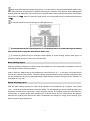
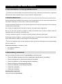
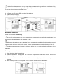
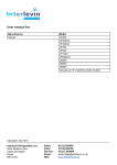
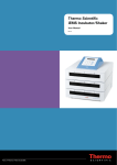
User manual for: Manufacturer Tefcold Model BLC Range Uploaded: Oct 2015 Interlevin Refrigeration Ltd West Meadow Rise Castle Donington Derby DE74 2HL Sales: Parts: Service: Email: Web 01332 850090 01332 850190 01332 850064 [email protected] www.interlevin.co.uk Blast Chillers/Freezers BLC3, BLC5, BLC10, BLC14 Users manual UK 0 1 1 CONTENT ENGLISH 1.REGULATIONS AND GENERAL INSTRUCTIONS .................................................................................. 1 1.1 General information ................................................................................................................................... 1 1.2 Replacement of Parts ................................................................................................................................ 1 1.3 Description of the Appliance ..................................................................................................................... 1 1.4 Features Plate............................................................................................................................................. 2 2. SAFETY.................................................................................................................................................... 3 3.RECOMMENDATIONS FOR USE ............................................................................................................ 4 Prolonged Inactivity .......................................................................................................................................... 4 Blast chilling Cycle ............................................................................................................................................ 5 Shock freezing Cycle........................................................................................................................................ 5 4.CLEANING AND MAINTENANCE ............................................................................................................ 6 4.1 Recommendations for Cleaning and Maintenance ............................................................................... 6 4.2 Routine Maintenance ................................................................................................................................. 6 4.3 Extraordinary maintenance ....................................................................................................................... 6 5.TROUBLE SHOOTING ............................................................................................................................. 8 6. INSTALLATION ........................................................................................................................................ 9 6.1 Packing And Unpacking ............................................................................................................................ 9 6.2 Installation ................................................................................................................................................... 9 6.3 Electric Power Supply Connection ........................................................................................................ 10 6.4 Inspection .................................................................................................................................................. 10 7.DISPOAL OF THE APPLIANCE ............................................................................................................. 11 8.REFRIGERANT RECHNICAL CARD ..................................................................................................... 11 XB570L BLAST CHILL&FREEEZER CONTROLLER ............................................................................. 12 9. General Features ................................................................................................................................... 12 10. Mounting & Installation ......................................................................................................................... 12 11. Electrical Connections .......................................................................................................................... 12 11.1 PROBES CONNECTION ...................................................................................................................... 13 12. Connections ......................................................................................................................................... 13 13. Frontal panel......................................................................................................................................... 13 14. QUICK START...................................................................................................................................... 13 14.1 DISPLAY.................................................................................................................................................. 13 14.2 KEYBOARD IN STAND-BY .................................................................................................................. 14 14.3 KEYBOARD WHEN A CYCLE 1,2,3,4 IS RUNNING ....................................................................... 15 14.4 KEYBOARD WHEN THE HOLDING CYCLE IS RUNNING (H) ..................................................... 16 14.5 OTHER KEYS......................................................................................................................................... 16 14.6 HOW TO START A MANUAL DEFROST .......................................................................................... 17 14.7 OTHER FUNCTIONS OF KEYBOARD .............................................................................................. 17 14.8 MEANING OF THE LEDS’.................................................................................................................... 17 15. How To Select A Cycle ......................................................................................................................... 18 15.1 HOW TO MODIFY A CYCLE ............................................................................................................... 18 16. Parameters ........................................................................................................................................... 18 PROBES .......................................................................................................................................................... 19 1 DISPLAY AND MEASUREMENT UNIT ...................................................................................................... 19 DIGITAL INPUTS ............................................................................................................................................ 19 AUXILIARY RELAY CONFIGURATION...................................................................................................... 20 SECOND RELAY MANAGEMENT............................................................................................................... 20 AUXILIARY RELAY MANAGEMENT ........................................................................................................... 21 DEFROST ........................................................................................................................................................ 21 FANS ................................................................................................................................................................ 21 TEMPERATURE ALARMS............................................................................................................................ 22 CYCLE LOG .................................................................................................................................................... 22 OTHER ............................................................................................................................................................. 22 17. How A Cycle Is Done ........................................................................................................................... 22 17.1 CONFIGURABLE CYCLE PARAMETERS ........................................................................................ 23 17.2 HOW TO USE THE INSERT PROBES .............................................................................................. 23 17.3 EXAMPLE OF A BLAST CHILLER CYCLE. ...................................................................................... 23 18. Installation and mounting ..................................................................................................................... 25 18.1 CUT OUT................................................................................................................................................. 25 18.2 MOUNTING............................................................................................................................................. 25 19. XB07PR - Printer (optional) ................................................................................................................. 26 19.1 PRINTER DIMENSIONS ...................................................................................................................... 26 19.2 PRINTER MOUNTING .......................................................................................................................... 26 19.3 CONNECTION TO THE XB570L – XB07PR ..................................................................................... 27 20. Electrical connections .......................................................................................................................... 27 20.1 PROBE CONNECTIONS ...................................................................................................................... 27 21. TTL Serial line ...................................................................................................................................... 27 22. Use of the programming “HOT KEY” ................................................................................................... 27 22.1 DOWNLOAD (FROM THE “HOT KEY” TO THE INSTRUMENT) .................................................. 27 22.2 UPLOAD (FROM THE INSTRUMENT TO THE “HOT KEY”) .......................................................... 28 23. ALARM SIGNALS ................................................................................................................................ 28 24. Technical data ...................................................................................................................................... 29 25. Standard Value of the cycles ............................................................................................................... 29 26. Standard Values of the parameters ..................................................................................................... 30 2 1.REGULATIONS AND GENERAL INSTRUCTIONS 1.1 General information This manual has been designed by the manufacturer to provide the necessary information to those who are authorized to interact with the appliance. The persons receiving the information must read it carefully and apply it strictly. Reading the information contained in this document will allow the user to prevent risks to personal health and safety. Keep this manual for the entire operating life of the equipment in a place which is well-known and easily accessible, so that it is always available when its consultation becomes necessary. Particular symbols have been used to highlight some parts of the text that are very important or to indicate some important specifications. Their meanings are given below: Indicates important information regarding safety. Behave appropriately so as not to risk the health and safety of persons or cause damage. Indicates particularly important technical information that must not be ignored 1.2 Replacement of Parts Activate all envisioned safety devices before carrying out any replacement intervention. In particular, deactivate the electrical power supply using the differential isolating switch. All responsibility is declined for injury to persons or damage to components deriving from the use of non-original spare parts and interventions which could modify the safety requisites,without authorization of the manufacturer. 1.3 Description of the Appliance The Blast chiller & freezer, from now on defined as appliance, has been designed and built to cool and/or freeze foodstuffs in the professional catering ambit. 1) Condensation area: it is positioned in the lower part and is characterized by the presence of the condensing unit. 2) Electric area: it is positioned in the lower part of the appliance and contains the control and power supply components as well as electric wiring. 3) Evaporation area: it is situated inside the refrigerated compartment in the rear and is characterized by the evaporating unit. 4) Storage area: it is situated inside the refrigerated compartment and is destined for the cooling and/or freezing of foodstuffs. 1 3-4 1 2 A The lower part is also distinguished by a control panel (A) that allows access to the electric parts; there is a vertically-opening door in the front, which closes the refrigerated compartment hermetically. Depending on requirements, the appliance is produced in several versions. BLC3 BLAST CHILLER/FREEZER Model suitable to contain 3 trays with blast chilling capacity of 12kg and 8 kg in shock freezing. BLC5 BLAST CHILLER/FREEZER Model suitable to contain 5 trays with blast chilling capacity of 18kg and 14kg in shock freezing. BLC10 BLAST CHILLER/FREEZER Model suitable to contain 10 trays with blast chilling capacity of 40kg and 28 kg in shock freezing. BLC14 BLAST CHILLER/FREEZER Model suitable to contain 14 trays with blast chilling capacity of 55kg and 38kg in shock freezing. 1.4 Features Plate The identification plate shown is applied directly onto the appliance. It states the reference and all indications indispensable for working in safety. (1) (2) (3) (4) (5) (6) (7) (8) Appliance code Description of the Appliance Serial number Power supply voltage and frequency Electrical absorption Climatic class Type and Amount of refrigerant gas WEEE symbol 2 2. SAFETY It is recommended to carefully read the instructions and warnings contained in this manual before using the appliance. The information contained in the manual is fundamental for the safety of use and for machine maintenance. Keep this manual carefully so that it can be Consulted when necessary. The electric plant has been designed in compliance with the IEC EN 60335-2-89 and EN 60335-1 standard. Specific adhesives highlight the presence of mains voltage in the proximity of areas(however protected)with risks of an electrical nature. Before the connection, ensure the presence of an omni polar switch with minimum contacts opening equal to 3 mm in the mains power supply upstream from the appliance (requested for appliances supplied without plug to connect to the fixed plant). In the design and construction phase, the manufacturer has paid particular attention to the aspects that can cause risks to safety and health of persons that interact with the appliance. Carefully read the instructions stated in the manual supplied and those applied directly to the machine, and particularly respect those regarding Safety. Don’t tamper or eliminate the installed safety devices. Failure to comply with this requisite can Lead to serious risks for personal health and safety. It is recommended to simulate some test manoeuvers in order to identify the controls, in particular those relative to switch-on and switch-off and their main functions. The appliance is only destined for the use for which it has been designed; any other use must be considered improper. The manufacturer declines all liability for any damage to objects or injury to persons owing to improper or incorrect use. All maintenance interventions that require precise technical skill or particular ability must be performed exclusively by qualified staff. When using the appliance, never obstruct the air inlet when the appliance is on,so as not to compromise its performance and safety. Never stretch the power cable. In order to guarantee hygiene and protect the food stuffs from contamination, the elements that come into direct or indirect contact with the foodstuffs must be cleaned very well along with the surrounding areas .These operations must only be performed using detergents that can be used with foodstuffs, 3 avoiding inflammable products or those that contain substances that are harmful to personal health. In the case of prolonged inactivity, as well as disconnecting all the supply lines, it is necessary to accurately clean all internal and external parts of the appliance. 3.RECOMMENDATIONS FOR USE Prolonged Inactivity If the appliance remains inactive for a long period, proceed as follows 1. Use the automatic isolating switch to deactivate connection to the main electrical line. 2. Clean the appliance and surrounding areas thoroughly. 3. Spread a thin layer of cooking oil onto the stainless steel surfaces 4. Carry out all maintenance operations 5. Leave the doors ajar to prevent the formation of mould and /or unpleasant odour. Recommendations for normal use In order to ensure correct use of the appliance, it is good practice to apply the following recommendations: Do not obstruct the zone in front of the condensing unit in order to favour heat disposal from the condenser to a maximum. Always keep the front of the condenser clean. Do not insert foodstuffs that are well above the temperature of 65℃. As well as initially overloading the machine it can make protections intervene that prolong temperature descent times. If possible , a brief external period is useful to lower the temperature to acceptable values. Check the planarity of the appliance rest surface. Do not stack the materials to be preserved in contact with the internal walls .so blocking the circulation of air, which guarantees uniformity of the internal temperature of the refrigerated compartment. There must be a sufficient space between the basins and trays used in order to guarantee a sufficient flow of cold air on the entire product. Therefore avoid the following positions of trays and/or basins stated below. Never obstruct the inlet of the evaporator fans. Products that are more difficult to chill because of their composition and size should be placed in the centre. Limit the number of times and the duration of time the doors are opened. Blast chilling data refer to standard products (low fat content )with a thickness below 50 mm: therefore avoid overlaying products or the insertion of pieces with a much higher thickness, This would ,in fact, lead to an extension of blast chilling times .Always distribute the product well on the trays or basins or in the case of thick pieces decrease the amount to blast chill. 4 After blast chilling/shock freezing the product, it can be stored in a preservation cabinet after having been duly protected .A tag should be applied describing the contents of the product, blast chilling/shock freezing date and expiry date. When the product has been blast chilled it must be preserved at a constant temperature of +2℃,while if it has been shock frozen it must be preserved at a constant temperature of -20℃。 The chiller should be used for storage for short periods only. To prevent bacterial contamination or contamination of any other biological nature, the needle probe must be disinfected after use. To extract the product that has undergone blast chilling or shock freezing ,always wear gloves to protect the hands ,as “burns” may occur form the cold. Blast chilling Cycle With this operating modality the chiller keeps the temperature of the refrigerating compartment close to zero during the entire chilling process in order to ensure a gradual drop in the temperature of the product to +3℃。In this way ,ice crystals do not form on the surface of the product .This blast chilling method should be used preferably for products that are not packed and whose physical/organoleptic characteristics could be damaged by the formation of superficial ice (e.g. fish) Shock freezing Cycle With this blast chilling modality the blast chiller maintains the temperature at a negative value below -18℃,which is the end temperature of shock freezing .For shock freezing to be successful and fast, food should be in small pieces, especially if it has a high fat content. The largest pieces should be placed in central trays .If it takes longer than standard time to shock freeze and the sizes cannot be reduced, decrease the quantity and precool the chiller compartment by starting an empty shock freezing cycle before shock freezing the product. 5 4.CLEANING AND MAINTENANCE 4.1 Recommendations for Cleaning and Maintenance Activate all envisioned safety devices before carrying out any maintenance interventions, In particular, deactivate the electrical power supply using the automatic isolating switch. 4.2 Routine Maintenance Routine maintenance consists of daily cleaning of all the parts which can into contact with foodstuffs and the periodic maintenance of the burners, nozzles and draining pipes. Correct maintenance allows the user to maximize performance levels and operating life and constantly maintain safety requirements. Do not spray the appliance with direct jets of water or using high pressure appliances. Do not use iron wool. brushes or scrapers to clean the stainless steel as ferrous particles could be deposited which ,on oxidizing, could lead to rust. To remove hardened residues, use wooden or plastic spatulas or abrasive rubber pads. During long periods of inactivity , spread a protective layer on all stainless steel surfaces by wiping them with a cloth soaked in Vaseline oil and airing the rooms periodically . Do not use products which contain substances which are harmful and dangerous for personal health (solvents. petrol etc) At the end of the day it is advisable to clean: the cooling compartment the appliance 4.3 Extraordinary maintenance Have the following operations carried out periodically by specialized staff: Check the perfect sealing of the door gaskets and replace them if necessary. Check that the electric connections have not loosened. Check the efficiency of the heating element resistance. Check functioning of the board and probes. Check the efficiency of the electrical system. Clean the evaporator. Clean the condenser. Cleaning the evaporator Clean the evaporator periodically. 6 As the fins of the evaporator are very sharp. always wear protective gloves for the next phases .Only a brush must be used for cleaning :do not use jets of liquid or sharp instruments. To access the evaporator proceed as follows: 1. 2. 3. 4. Open the door(A) of the appliance. Loosen the two screws (B)on the right of the deflector. Remove the runners(C) Turn the deflector(D) to the left. Clean the condenser Clean the condenser periodically As the fins of the condenser are very sharp, always wear protective gloves for the next phases. Use protective masks and glasses in the presence of dust Whenever the condenser has a deposit of dust in correspondence with the fins, this can be removed using a suction device or with a brush applied, using a vertical movement along the direction of the fins. No other instruments must be used, which may deform the fins and therefore the efficiency of the appliance. To clean, proceed as follows: 1. Open the door (A) of the appliances. 2. Remove the lower panel(B) from the technical compartment: to do this, remove the screw fasteners(C) 3. It is now possible to clean the finned part of the condenser (D) using suitable tools and protection devices. 4. After cleaning, close the control panel and fix it with the screws removed beforehand. 7 5.TROUBLE SHOOTING The information shown below aims to help with the identification and correction of any anomalies and malfunctions which could occur during use. Some of these problems can be resolved by the user. For the others, precise skill is required and they must therefore only be carried out by qualified staff. Problem Causes Solutions Check the power supply cable No voltage The refrigerator unit does not start Check fuses Check the correct connection of the appliance Other causes If the problem persists, contact the after-sales centre The refrigerator unit functions continuously, cooling insufficiently Room too hot Air the environment Dirty condenser Clean the condenser Insufficient door sealing Check the gaskets Insufficient quantity of refrigerant gas Condenser fan at a standstill Contact the after-sales centre Contact the after-sales centre Evaporator fan standstill Contact the after-sales centre Probe faulty Contact the after-sales centre The refrigerator unit does not stop Circuit board fault Contact the after-sales centre Carry out a defrosting cycle possibly with the door open Presence of ice inside the evaporator If the problem persists, contact the after-sales centre Appliance noise Persistent vibrations 8 Check there is no contact between the appliance and other objects inside or outside 6. INSTALLATION 6.1 Packing And Unpacking Handle and install the appliance respecting the information provided by the manufacturer, shown directly on the packaging, on the appliance and in this manual. The lifting and transportation system of the packaged product envisions the use of a fork-lift truck or a pallet stacker. When using these, particular attention must be paid to balancing the weight in order to prevent the risk of overturning(avoid excessive tilting!). ATTENTION: When inserting the lifting device, pay attention to the power supply cable and the position of the feet. The packaging is made of cardboard and the pallet of plywood. A series of symbols is printed on the cardboard packaging which highlights, in accordance with international standards, the provisions to which the appliances are subjected during loading, unloading, transport and storage. On delivery, check that the packaging is intact and has not undergone any damage during transportation. The transportation company must be notified of any damage immediately. The appliance must be unpacked as soon as possible to check that it is intact and undamaged. Do not cut the cardboard with sharp tools so as not to damage to the steel panels underneath. Pull the cardboard packaging upwards. After having unpacked the appliance, check that the features correspond to those requested in the order; Contact the dealer immediately if there are any anomalies. Packaging elements (nylon bags, polystyrene foam, staples…) must not be left within reach of children. Remove the protective PVC film from the internal and external walls, avoiding the use of metal tools. 6.2 Installation All the installation phases must be considered, from the moment of creation of the general plan. The installation area must be equipped with all power supply and production residue drainage connections and must be suitably lit and respect current laws regarding hygiene and sanitary requirements. The performance of the appliance is guaranteed with a room temperature of 32℃. A higher 9 temperature can compromise its performance and, in more serious cases, cause the appliance’s protections to start up. Therefore, consider the most critical room conditions that can be reached in that position before making a choice. Level the appliance by acting on the individual feet. This appliance can only be installed and operate in rooms which are permanently ventilated, in order to guarantee correct operation. Connect and leave for a certain period of time (at least 2 hours) before checking functioning. During transport it is probable that the compressor lubricant oil has entered the refrigerant circuit blocking the capillary: as a consequence the appliance will function for a certain period of time without producing cold until the oil has returned to the compressor. ATTENTION: the appliance requires the minimum functioning spaces, as shown in the attachments. The defrosting water and the water that forms at the bottom of the refrigerating compartment during operation or during periodical internal cleaning must be drained through a prearranged hose with a minimum diameter 3/4 connected to the hose at the bottom of the chiller. A drain trap should also be guaranteed. The drain must be in compliance with Standards in force. 6.3 Electric Power Supply Connection Connection must be carried out by authorized and qualified staff, respecting the current laws regarding the subject and using appropriate prescribed material. Before connecting the appliance to the electric mains, check that the voltage and the frequency correspond to the data stated on the registration plate applied in the rear of the appliance. Before connection, ensure the presence of a relevant differential switch with adequate power in the mains power supply, upstream from the appliance, in order to protect the appliance from overloads or short circuits 6.4 Inspection The appliance is delivered in conditions such that it can be started-up by the user. This functionality is guaranteed by passing the tests (electric inspection-functional inspection, appearance inspection) and relative certification through the specific attachments. At least the following should be checked after installation: Check the electric connections. Check the functionality and efficiency of drains. Check that there are no tools or materials left in the appliance that could jeopardize its functionality or even damage the machine. Have the appliance perform at least one complete chill blasting/shock freezing cycle. 10 7.DISPOAL OF THE APPLIANCE This appliance is marked in compliance with the 2002/96/EC European Directive. WASTE ELECTRICAL AND ELECTRIC EQUIPMENT (WEEE). By assuring that this product is disposed of correctly, the user contributes to preventing the potential negative consequences on the environment and health. The symbol found on the product or on the accompanying documentation indicates that this product must not be treated as domestic waste but must be taken to suitable collection points for the recycling of electric and electronic appliances. Dispose of it following local regulations regarding waste disposal. For further information regarding the treatment, recovery and recycling of this product, contact the relevant local office, the domestic waste collection service or the shop where the product was purchased. 8.REFRIGERANT RECHNICAL CARD The refrigerant used in the machine is R404a fluid. Below find the components of the fluid: PENTAFLUOROETANE (HFC R125)44% ETHANE 1, 1, 1-TRIFLUORO (HFC R143A)52% ETHANE 1, 1, 1, 2 TERAFLUORO (HFC R134A)4% IDENTIFICATION OF DANGERS The rapid evaporation of the liquid can cause freezing. The inhalation of high concentrations of vapour can cause irregular heartbeat, short term narcotic effects (including vertigo , headache and mental confusion), fainting and death. Effects to the eyes: Freezing or cold burns caused by contact with the liquid. Effects on the skin: Freezing or cold burns caused by contact with the liquid. Effects of ingestion. Ingestion is not considered a means of exposure. FIRST AID Eyes: In the case of contact, wash the eye well using a large amount of water for at least 15 minutes. Consult a doctor. Effects on the skin: Wash with water for at least 15 minutes after excessive contact. If necessary, cure freezing by gently warming the area in question. Consult a doctor in the case of irritation. Ingestion: Ingestion is not considered a means if exposure. Inhalation: If large concentrations are inhaled, go into the open air, Keep the person calm. If the person cannot breath, perform artificial respiration. If respiration is difficult, apply oxygen. Consult a doctor. 11 XB570L BLAST CHILL&FREEEZER CONTROLLER 9. General Features The series XB has been created for fast chilling or freezing goods according to international food safety standards. There are FOUR types of cycles: The CYCLES: Cy1, Cy2, Cy3, Cy4 are pre-set according to the most common cycles used in food safety applications; the user can select one of them according to his own requirements and modify it as he wants. Any cycle can be manually terminated before the normal. Any cycle can use the insert probe, it measures the internal temperature of the product. During the Cycle there are no defrosts and the fans are always on, a defrost cycle can be done before any freezing cycle. The cycle is divided up to 3 phases completely configurable by the user. Each instrument is provided with an output for remote display XR REP, which shows the temperature of cabinets or goods. The XB570L controller is provided with internal real time clock and can be connected to the XB07PR printer. This means that a report, which includes all the main features of cycle, can be printed: start and end of the cycle, length of the cycle, logging of the temperature of the cabinet and goods. 10. Mounting & Installation Model XB570L is a controller panel mounted, hole dims 150x31 mm, and fixed with the screws. The ambient operating temperature range is 0÷60°C. Avoid locations subject to heavy vibration, corrosive gases or excessive dirt. The same applies to the probes. Ensure ventilation around the instrument. 11. Electrical Connections The instruments are provided with a screw terminal block to connect cables with a cross section up to 2,5mm² for probes and digital input. Spade on 6,3mm heat-resistant wiring for supply and loads. Before connecting cables make sure the power supply complies with the instrument’s requirements. Separate the input connection cables from the power. supply cables, from the outputs and the power connections. Do not exceed the maximum current allowed on each relay, in case of heavier loads use a suitable external relay. 12 11.1 PROBES CONNECTION The probes shall be mounted with the bulb upwards to prevent damages due to casual liquid infiltration. It is recommended to place the thermostat probe away from air streams to correctly measure the average room temperature. Place the defrost termination probe among the evaporator fins in the coldest place, where most ice is formed, far from heaters and from the warmest place during defrost, to prevent premature defrost termination. 12. Connections 13. Frontal panel 14. QUICK START 14.1 DISPLAY The upper display shows the temperature of the room probe. The lower display shows the temperature of the inserts probe or the count down timer. To pass to the one insert probe to the another one use the DOWN key. DISPLAY Temperature. Timer or insert probe Alarm and status icons. If an icon or LED is on, the correspondent Function is enabled. If an icon or LED is flashing, the correspondent function is delayed. 13 14.2 KEYBOARD IN STAND-BY HOW TO SELECT A CYCLE: Push and release the (3) key till the desired cycle is selected. HOW TO START A CYCLE: Push and release the START/STOP button (2). Il The correspondent yellow LED is switched on.. HOW TO TEMPORARILY STOP THE RUNNING CYCLE. 1. Press and release the key. 2. The compressor and the fan will be stopped for the PAU time (see parameters list) and the flashing message “Stb” will be displayed. 3. To restart the cycle press and release the key, the cycle will restart from the some point at which it was interrupted. 4. In any case the cycle automatically restarts after the PAU time. HOW TO STOP A CYCLE: hold pushed the START/STOP button (2) till the yellow LED will be switched off. HOW TO SET THE TIME (RTC) Hold pushed the DOWN key (5) till the Min label is displayed. Use the UP and DOWN KEY to browse the parameters. TO MODIFY: push the SET button and then the UP and DOWN keys. TO CONFIRM: push the SET button. TO EXIT THE RTC MENU: Push together SET + UP keys or wait 5 sec. 1. HOW DISPLAY / MODIFY THE SET POINT OF THE HOLDING PHASE TO DISPLAY: Push and release the SET key (6), the holding set point of the selected cycle is displayed for 5 sed.. TO MODIFY: while the set point is displayed hold pushed the SET key till the HdS label start flashing. Use the UP and DOWN key to modify the value. TO CONFIRM: push the SET key to confirm the value and exit. In this exemplum the holding set point of the cycle 1 is modified. 14 HOW MODIFY A CYCLE: 1. Push the 2. 3. 5. 6. key (6) for several seconds till the first parameter (CyS) is displayed. Use the UP and DOWN keys to browse the parameters. To modify a parameter push the SET key and use the arrow keys. Confirm the new value by pushing the SET key. The new value is recorded even if the programming is exited by time out. 14.3 KEYBOARD WHEN A CYCLE 1,2,3,4 IS RUNNING DISPLAY TEMPERATURES: The upper display shows the temperature of the thermostat probe The bottom display shows the temperature of a insert probe (if enabled) or the count down timer. By pushing the DOWN key the probes iP1, iP2, iP3 and the count down timer are displayed in sequence. PHASE DISPLAY: pushing the UP key the running phase is displayed. HOW TO DISPLAY THE REGULATION SET POINTS By pushing the SET key the following information are displayed in sequence: - rSI = Room set point - iSI = Stop phase set point, referred to the insert probe - Back to the room temperature. HOW TO MODIFY THE ROOM SET POINT While rSI or iSI are displayed hold pushed the SET key till the rSi or iSi label start flashing and LED near the SET key is turned on.. Use the arrow key to modify the value and the SET key to confirm it. 15 14.4 KEYBOARD WHEN THE HOLDING CYCLE IS RUNNING (H) HOW TO DISPLAY THE HOLDING (REGULATION) SET POINT While the holding cycle is running, (H icon lighted), push the SET key and the holding set point is displayed on the UPPER display while the SETH label on the bottom display HOW TO MODIFY THE ROOM SET POINT While SETH is displayed hold pushed the SET key till the SETH label starts flashing and LED near the SET key is turned on.. Use the arrow key to modify the value and the SET key to confirm it. TO CONFIRM AND EXIT: push again the SET key 14.5 OTHER KEYS LIGHT (4): push the LIGHT (4) key to switch the light on and off. The status of the light is monitored by the yellow LED upper the key. AUX (8): push the AUX (8) key to switch the auxiliary on and off. The status of the auxiliary relay is monitored by the yellow LED upper the key. PRINTER / H (7): push the PRINTER key when the keyboard is connected to the controller, to enabled/ disable the printer. PRINTER CONFIGURATION MENU Push the PRINTER (7) key for few seconds to enter the printer configuration menu. The itP, label is displayed, use the ARROW keys to browse the parameters To modify: push the SET key and then the ARROW keys. To confirm: push the SET key To exit the Printer menu: Push together SET + UP keys or wait 5 sec 16 14.6 HOW TO START A MANUAL DEFROST Assure that none cycle is active or the hold mode is running. 1. Hold press the UP key fro few seconds. NOTE: The defrost will not be done if the temperature detected by the evaporator probe is higher than EdF (stop defrost temperature) parameter. 14.7 OTHER FUNCTIONS OF KEYBOARD To lock & unlock the keyboard Pon/PoF + To enter the programming mode when the controller is in stand-by Each parameter present in the Pr2 can be removed or put into “Pr1” (user level) by pressing “SET + ▼”. + To return to the previous menu. + 14.8 MEANING OF THE LEDS’ A series of light points on the front panels is used to monitor the loads controlled by the instrument. Each LED function is described in the following table. LED MODE ON Flashing ACTION - Compressor enabled - Programming Phase (flashing with LED ) - Anti-short cycle delay enabled ON Flashing - Fans enabled - Programming Phase (flashing with LED ) - Activation delay active ON Flashing ①②③④ H ①②③④ H AUX –AUX2 ON Flashing - Defrost active - Drip time active - Freezing cycle 1, 2, 3, 4 or hold mode active - Instrument temporarily stop ON - Alarm signalling ON - Aux or Aux2 enabled 17 15. How To Select A Cycle 1. Push the to move among the cycles C1, C2, C3, C4 and the holding cycle. The related symbol on the display will be lighted and the cycle will be selected. NOTE: to pass from a cycle to another one simply push the key when the controller is in stand–by mode. HOLD PHASE: To select H symbol pushing the . Cycles are pre-set with the following values: 1. 2. 3. 4. 5. 6. Cy1: for fast chilling and conservation of foods (hard +soft chill). Cy2: for chilling and fast freezing avoiding ice skin (hard +soft + freezing cycle). Cy3: for fast freezing (fast freezing + freezing cycle) Cy4: for direct fast freezing (only fast freezing cycle) HLd: hold mode function dEF: for starting a manual defrost 2. Now the cycle is memorized and can be activated. 15.1 HOW TO MODIFY A CYCLE 1. Verify that none cycle is running. If one cycle is running stop it by pushing the 2. Push the key for 3s. to move among the cycles C1, C2, C3, C4 and the holding cycle. The related symbol on the display will be lighted and the cycle will be selected 3. Hold push the key for several seconds till the display will show the first parameter of the selected cycle (CyS) with its value. 4. Use the UP and DOWN keys to browse the parameters. 5. To modify a parameter push the SET key and use the arrow keys. 6. Confirm the new value by pushing the SET key. 7. The new value is recorded even if the programming is exited by time out. TO exit: wait 30s or push the SET+UP keys. 16. Parameters Hy Intervention differential for set point: (0,1 ÷ 12,0 /0,1°C/1°F), always positive. Compressor cut IN is Set Point Plus Differential (Hy). Compressor cut OUT is when the temperature reaches the set point. AC Anti-short cycle delay: (0÷30 min) minimum interval between the compressor stop and the following restart. PAU Time of stand by: (0 ÷ 60min) after this time the controller restart the cycle. PFt Maximum acceptable duration of power failure: (0 ÷ 250 min) if power failure duration is less than PFt, the cycle restarts from the same point at which it was stopped otherwise the cycle restarts from 18 the beginning of the current phase. Con Compressor ON time with faulty probe: (0÷ 255 min) time during which the compressor is active in case of faulty thermostat probe. With COn=0 compressor is always OFF COF Compressor OFF time with faulty probe: (0÷255 min) time during which the compressor is off in case of faulty thermostat probe. With COF=0 compressor is always active PROBES rPO Thermostat probe calibration (-12,0 ÷ 12,0; res. 0,1 °C /1°F) EPP Evaporator probe presence (not present in the XB350C): (no / YES) no: not present (timed defrost); YES: present (end defrost ) EPO Evaporator probe calibration (not present in the XB350C): (-12,0 ÷ 12,0; res. 0,1 °C /1°F) i1P Insert probe 1 presence (no / YES) no: not present; YES: present. i1o Insert probe 1 calibration (-12,0 ÷ 12,0; res. 0,1 °C /1°F) i2P Insert probe 2 presence (no / YES) no: not present; YES: present. i2o Insert probe 2 calibration (-12,0 ÷ 12,0; res. 0,1 °C /1°F) i3P Insert probe 3 presence (no / YES) no: not present; YES: present. i3o Insert probe 3 calibration (-12,0 ÷ 12,0; res. 0,1 °C /1°F) rEM End cycle probe selection. (iPt, rP). It sets which probe stops teh the cycle, thermostat probe or insert probe. iPt = insert probe; rPt =thermostat probe NOTE, with rEM = rPt when the cycles are done by temperature, the rSi values are used as stop of the cycle. DISPLAY AND MEASUREMENT UNIT CF Temperature measurement unit: °C =Celsius; °F =Fahrenheit rES Resolution (for °C): in: integer; de: with decimal point Lod Upper display visualization: select which probe is shown by the upper display: rP = Thermostat probe EP = Evaporator probe rEd Remote display, X-REP, visualization: select which probe is displayed by the X-REP: rP = Thermostat probe; EP = Evaporator probe; tiM: cycle count down; i1P = insert probe 1; i2P = insert probe 2; i3P = insert probe 3. DIGITAL INPUTS d1P: Door switch input polarity (25-26): (OP÷CL)select if the digital input is activated by opening or closing the contact. OP= opening; CL=closing odc Compressor and fan status when open door: no = normal; Fan = Fan OFF; CPr = Compressor(s) OFF; F_C = Compressor(s) and fan OFF. doA Open door alarm delay:(0÷254min,nu) delay between the detection of the open door condition and its 19 alarm signalling: the flashing message “dA” is displayed. If doA=nu the door alarm will be not signalled. dLc Stop count down of the running cycle with door open y = count down is stopped with door openi; n= count down goes on with door open; rrd Regulation restart with door open alarm: y = count down and regualtion restart when door open alarm is signalled.; n = compressor and fans stay according to the odc parameter when door open alarm is signalled. d2F(EAL, bAL,) Second digital input configuration (26-27): EAL: external alarm; bAL: serious alarm, regulation is stopped.; d2P: Configurable digital input polarity (26-27): (OP÷CL)select if the digital input is activated by opening or closing the contact. OP= opening; CL=closing did Time delay for digital input alarm:(0÷255 min.) If d2F=EAL or bAL (external alarms), “did” parameter defines the time delay between the detection and the successive signalling of the alarm. AUXILIARY RELAY CONFIGURATION oA1 First auxiliary relay configuration (7-8): ALL: alarm; Lig: light; AuS: Second thermostat; tMr: auxiliary relay enabled by keyboard C2: Second compressor: it always is switched on during the Cycles, during the holding depends on the 2CH parameter oA2 First auxiliary relay configuration (1-2): ALL: alarm; Lig: light; AuS: Second thermostat; tMr: auxiliary relay enabled by keyboard C2: Second compressor: it always is switched on during the Cycles, during the holding depends on the 2CH parameter oA3 First auxiliary relay configuration (9-10) ALL: alarm; Lig: light; AuS: Second thermostat; tMr: auxiliary relay enabled by keyboard C2: Second compressor: it always is switched on during the Cycles, during the holding depends on the2CH parameter SECOND RELAY MANAGEMENT 2CH Compressors setting during the holding phase: (used only if one OAi =C2) The second compressor is always switched on during the phases, during the holding depends on this parameter. The 2CH sets which compressor is used during the holding phase. Second compressor operates on set + OAS. (whit set= set loaded during the holding phase of each cycle). It starts oAt min. after the first compressor The following table shows how it works: Holding 2CH =C1 C1 on; 2CH =C2 C2 on 2CH =1C2 C1 on; C2 On OAt Second compressor switching on delay: (0÷255 min) time delay between the switching on of the first and second compressor. OAS Set point for second compressor (-50÷50; ris.1 °C/ 1°F) This set point is a differential add to the set point of the first compressor. 20 ES. OAS=0 the set point of the second compressor s the same set point of the first compressor. OAS=5 the set point of the second compressor is SET (of first compressor) + 5; OAS=-5 the set point of the second compressor is SET (of first compressor) - 5; OAH Differential for second compressor: (-12.0÷12,0; ris.0,1°C/1°F, always ¹0) second compressor cut IN is SETH+OAS+OAH. Second compressor cut out is when the temperature SETH+OAS. OAi Probe selection for the second compressor: rP =Thermostat probe; EP = Evaporator probe; tiM: cycle count down; i1P = insert probe 1; i2P = insert probe 2; i3P = insert probe 3. AUXILIARY RELAY MANAGEMENT OSt AUX output timer: (0÷255 min) time in which the AUX output stays ON. It is used when oA1 or oA2 or oA3 = tMr. With oAt = 0 the AUX relay is switched on and off only manually. OSS Set point for AUX output, used when oA1 or oA2 or oA3 = AUS (-50÷50; ris.1 °C/ 1°F) OSH Differential for AUX output: (-12.0÷12,0; ris.0,1°C/1°F, always ¹0) Intervention differential for the set point of the AUX output, with OAH<0 the action is for heating, with OAH>0 it is for cooling. COOLING, OSH >0: AUX output cut IN is OSS+OAH. Second compressor cut out is when the temperature SETH+OAS. HEATING, OSH <0: second compressor cut IN is OSS-OAH. Second compressor cut out is when the temperature OSS OSi Probe selection for the second compressor: rP =Thermostat probe; EP = Evaporator probe; tiM: cycle count down; i1P = insert probe 1; i2P = insert probe 2; i3P = insert probe 3. DEFROST tdF Defrost type (not present in the XB350C): (rE= electrical heater; in = hot gas). IdF Interval between defrost cycles: (0.1÷ 24.0; res. 10 min) Determines the time interval between the beginning of two defrost cycles. (with 0.0 the defrost is disabled) dtE Defrost termination temperature: (-50÷50 °C/°F) Sets the temperature measured by the evaporator probe, which terminates the defrost. Used only if EPP =YES MdF Maximum length for defrost: (0÷255 min) When EPP = no (timed defrost) it sets the defrost duration, when EPP = YES (defrost termination based on temperature) it sets the maximum length for defrost. dFd Temperature displayed during defrost: (rt , it, SEt, dEF) rt: real temperature; it: temperature at the start of defrost; SEt: set point; dEF: “dEF” message Fdt Drip time: (0 ÷ 60 min) Time interval between reaching defrost termination temperature and the restoring of the controllers' normal operation. This time allows the evaporator to eliminate water drops that might have formed during defrost. dAd Defrost display time out: (0÷120 min) Sets the maximum time between the end of defrost and the restarting of the real room temperature display. FANS FnC Fans operating mode during the holding phase: o-n = continuous mode, OFF during defrost; C1n= runs in parallel with the first compressor, OFF during defrost; C2n= runs in parallel with the second compressor, OFF during defrost; 21 Cn= runs in parallel with compressors, OFF during defrost; o-Y = continuous mode, on during defrost; C1y= runs in parallel with the first compressor, on during defrost; C2y= runs in parallel with the second compressor, on during defrost; Cy= runs in parallel with compressors, on during defrost; FSt Fan stop temperature: (-50÷50°C/°F; res. 1°C/1°F).It used only if the EPP = yES. If the temperature. detected by the evaporator probe is above FSt fans are stopped. It serves to avoid blowing warm air in the room. AFH Differential for the stop temperature and for the alarm (0.1 ÷ 25.0 °C; ris.0.1°C/1°F) Fans carry on working when the temperature reaches the FSt-AFH value, the temperature alarm recovers when the temperature is AFH degrees below the alarm set. Fnd Fan delay after defrost: (0 ÷ 255 min) The time interval between end of defrost and evaporator fans start. TEMPERATURE ALARMS ALU MAXIMUM temperature alarm (it is used only during the holding phase): (1 ÷ 50 °C/°F) When the “SET+ALU” temperature is reached the alarm is enabled, (possibly after the “ALd” delay time). ALL Minimum temperature alarm (it is used only during the holding phase): (1÷50°C/1°F) When the “SET-ALL” temperature is reached the alarm is enabled, (possibly after the “ALd” delay time). ALd Temperature alarm delay (it is used only during the holding phase): (0÷255 min) time interval between the detection of an alarm condition and alarm signalling. EdA Temperature alarm delay at the end of defrost (it is used only during the holding phase): (0 ÷ 255 min) Time interval between the detection of the temperature alarm condition at the end of defrost and alarm signalling. tbA Silencing alarm relay: (Yes= silencing buzzer and alarm relay, no= only buzzer silencing). CYCLE LOG tCy duration of the last cycle (readable only); tP1 duration of first phase of the last cycle (readable only); tP2 duration of second phase of the last cycle (readable only); tP3 duration of third phase of the last cycle (readable only); OTHER Adr Address for RS485: (1 ÷247) bUt Buzzer activation at the end of the cycle (0÷60s; with 0 the buzzer is on till a key is pushed) tPb Kind of probe: it sets the kind of probe used: ntc = NTC o Ptc = PTC. rEL Release code (readable only) Ptb Parameter code (readable only) 17. How A Cycle Is Done 1. Every programmable cycle Cy1, Cy2, Cy3 or Cy4 can be divided into up to 3 phases usually called: • hard chill 22 • soft chill • freezing cycle 2. For each phase there are 3 parameters. iS1, (iS 2, iS 3): Set point related to the insert probes that stops the current phase. rS1, (rS2, rS3): set point of the room temperature for each phase. Pd1, (Pd2, Pd3): the maximum duration time for each phase. Hds : set point of the hold phase at the end of the whole cycle. There are also 3 parameters: first one concerning the cycle way of doing the cycle: by temperature or by time, the other two are related to the defrost. These are dbC = defrost before cycle, dbH = defrost before holding (at the end of the cycle). 17.1 CONFIGURABLE CYCLE PARAMETERS cyS Cycle setting: tEP = by temperature. the cycle is done according to the rEM parameter; tiM: timed cycle, based on the Pd1, Pd2, Pd3 parameters. dbc (yes/no) Defrost before the cycle iS1 (-50÷50°C;1°C/1°F) Insert Probe Set point: when the temperature measured by the three insert probes reaches this value the first phase is ended. rS1(-50÷50°C; 1°C/1°F) Room probe Set point for the first phase: it prevents temperature from reaching a too low value during the hard cycle. Pd1 (OFF÷4.0h;10 min)Maximum time for first phase iS2 (-50÷50°C; 1°C/1°F) Insert probe set point when the temperature measured by the three insert probes reaches this value the second phase is ended. rS2 (-50÷50°C; 1°C/1°F) Room probe Set point for the second phase: it prevents temperature from reaching a too low value during the second phase. Pd2 OFF÷4.0h; res. 10 min Maximum time for second phase. iS3 (-50÷50°C; 1°C/1°F) Insert Probe Set point to stop the third (and last) phase: when the temperature measured by the three insert probes reaches this value the third phase is ended. rS3 (-50÷50°C; 1°C/1°F) Room probe Set point for the third (and last) phase: it prevents temperature from reaching a too low value during the third (and last) phase. Pd3 (OFF÷4.0h; 10 min) Maximum time for the third phase. dbH (yes / no) defrost before the hold phase HdS (-50÷50 - OFF; 1 °C / 1°F) Set point of the holding phase. With “OFF” the hold phase is disabled. IMPORTANT NOTE: If the duration time of a phase is set at the OFF value, the corresponding phase is disabled. E.g. If Pd3= 0FF the third phase of the cycle is not active. 17.2 HOW TO USE THE INSERT PROBES By means the insert probe, the internal temperature of products can be checked. This measure is used to end the various phase of the cycle. A special internal function detect if the inset probe is not used, in this case the cycle is made by time 17.3 EXAMPLE OF A BLAST CHILLER CYCLE. The following drawing explains how a Blast Chiller cycle can be done. 23 17.3.1 First phase: “Hard chill”. It is normally used to fast chill hot foods. E.g. from 80°C / 170°F to 20°C / 70°F During “Hard Chill”, both compressor and fan are always on until the rS1 temperature is reached. At this point compressor is turned on end off so as to keep the temperature of the room at the rS1 value. “Hard Chill” ends when the temperature measured by the 3 insert probes reach the iS1 value. 17.3.2 Second phase: “Soft chill”. The Soft Chill starts when the Hard Chill ends. It is used to prevent thin layer of ice from forming on the product. The Soft Chill lasts until the temperature measured by the 3 insert probes reach the set point iS2 (usually 4 or 5°C). During Soft Chill the temperature of the room is regulated by the ambient probe with the set point rS2 (normally at 0 or 1 °C / 32 or 34°F). When the box temperature reaches the rS2 value compressor is turned on end off so as to keep the temperature of the box at this value. 17.3.3 Third phase: “Freezing cycle”. Freezing Cycle: used to fast freeze foods. The Freezing Cycle starts when the Soft Chill ends. During the “Freezing Cycle” both compressor and fan are always on until the rS3 temperature is reached. At this point compressor and fans are turned on end off so as to keep the temperature of the room at the rS3 value (normally some degrees below iS3). Freezing Cycle ends when the temperature measured by the 3 insert probes reach the iS3 value (normally -18°C / 0°F), in any case it ends when the maximum time Pd1 + Pd2 + Pd3 has expired. 17.3.4 End of the Blast Chill cycle and starting of the Hold Mode. When one of the three insert probes reaches the iS3 value the values End followed by the i1P or i2P or i3P are shown on the display. Cycle ends when all the probes have reached the iS3 value. A signal is generated: buzzer and alarm relay is turned ON, the display shows the message “End” alternating with the room temperature. The alarm automatically stops after the “but” time or by pressing any keys. At the end of the cycle the controller can start the “Hold mode” keeping the room temperature at the value set in HdS parameter. If HdS = OFF, the machine is turned OFF. NOTE1: with dbH = yES a defrost is done before the holding phase. NOTE2: If the end cycle temperature iS3 is not reached in the maximum time Pd1+Pd2+Pd3 the 24 instrument keep on working, but the alarm message “OCF” is given. 18. Installation and mounting Instruments XB570L shall be mounted on vertical panel, in a 150x31 mm hole, and fixed using two screws ø 3 x 2mm. To obtain an IP65 protection grade use the front panel rubber gasket (mod. RG-L). The temperature range allowed for correct operation is 0 - 60 °C. Avoid places subject to strong vibrations, corrosive gases, excessive dirt or humidity. The same recommendations apply to probes. Let the air circulate by the cooling holes. 18.1 CUT OUT 18.2 MOUNTING 25 19. XB07PR - Printer (optional) The XB570L is designed to work with the XB07PR. The XB07PR kit is composed by: 1. Printer 2. Power adapter 3. Connecting cables 19.1 PRINTER DIMENSIONS 19.2 PRINTER MOUNTING SCREW FIXING PANEL CUT OUT 26 19.3 CONNECTION TO THE XB570L – XB07PR 20. Electrical connections The instruments are provided with screw terminal block to connect cables with a cross section up to 2,5 mm2 for the digital and analogue inputs. Relays and power supply have a Fast on connection (6,3mm). Heat resistant cables have to be used. Before connecting cables make sure the power supply complies with the instrument’s requirements. Separate the probe cables from the power supply cables, from the outputs and the power connections. Do not exceed the maximum current allowed on each relay, in case of heavier loads use a suitable external relay. N.B. Maximum current allowed for all the loads is 20A. 20.1 PROBE CONNECTIONS The probes shall be mounted with the bulb upwards to prevent damages due to casual liquid infiltration. It is recommended to place the thermostat probe away from air streams to correctly measure the average room temperature. 21. TTL Serial line The TTL connector allows, by means of the external module TTL/RS485, to connect the unit to a network line ModBUS-RTU compatible as the DIXEL monitoring system XJ500 (Version 3.0). The same TTL connector is used to upload and download the parameter list of the “HOT KEY“. 22. Use of the programming “HOT KEY” The Wing units can UPLOAD or DOWNLOAD the parameter list from its own E2 internal memory to the “Hot Key” and vice-versa. 22.1 DOWNLOAD (FROM THE “HOT KEY” TO THE INSTRUMENT) 1. Turn OFF the instrument by means of the ON/OFF key, remove the TTL serial cable if present, insert the “Hot Key” and then turn the Wing ON. 27 2. Automatically the parameter list of the “Hot Key” is downloaded into the Wing memory, the “DoL” message is blinking. After 10 seconds the instrument will restart working with the new parameters. 3. Turn OFF the instrument remove the “Hot Key”, plug in the TTL serial cable, then turn it ON again. At the end of the data transfer phase the instrument displays the following messages: “end “ for right programming. The instrument starts regularly with the new programming. “err” for failed programming. In this case turn the unit off and then on if you want to restart the download again or remove the “Hot key” to abort the operation. 22.2 UPLOAD (FROM THE INSTRUMENT TO THE “HOT KEY”) 1. Turn OFF the instrument by means of the ON/OFF key and remove the TTL serial cable if present; then turn it ON again. 2. When the Wing unit is ON, insert the “Hot key” and push o key; the "uPL" message appears. 3. Push “SET” key to start the UPLOAD; the “uPL” message is blinking. 4. Turn OFF the instrument remove the “Hot Key”, plug in the TTL serial cable, then turn it ON again. At the end of the data transfer phase the instrument displays the following messages: “end “ for right programming. “err” for failed programming. In this case push “SET” key if you want to restart the programming again or remove the not programmed “Hot key”. 23. ALARM SIGNALS Mess Cause Outputs “EE” Data or memory failure Alarm output ON; Other outputs unchanged “rPF” Thermostat Probe failure Alarm output ON; Compressor output according to parameters “COn” and “COF” “EPF” Evaporator Probe failure Alarm output ON; Defrost termination is timed; No temperature control on fans. “i1P” “i2P” “i3P” Insert probe 1, 2, 3, failure Alarm output ON; Other outputs unchanged; The cycle is made by time “rtC” Real Time Clock data lost Alarm output ON; Other outputs unchanged; “rtF” Real Time Clock failure Alarm output ON; Other outputs unchanged; The date and the duration of the cycle are not available. “HA” Maximum temperature alarm Alarm output ON; Other outputs unchanged “LA” Minimum temperature alarm Alarm output ON; Other outputs unchanged. “FF” Fast freezing interrupted by shortpower failure Alarm output ON; The freezing cycle restart from the same point at which was interrupted. “PFA” Fast freezing interrupted by long power failure Alarm output ON; The freezing cycle restart from the current phase. “OCF” Max duration of the cycle is expired Alarm output ON; Other outputs unchanged. In any case the cycle ends when the final temperature is reached “EA” External alarm Alarm output ON; Other outputs unchanged. “CA” Serious external alarm Alarm output ON; Other outputs OFF. “dA” Door open alarm Alarm output ON; Other outputs unchanged. 28 24. Technical data Housing: self extinguishing ABS. Case: frontal 185x38 mm; depth 70mm; Mounting: panel mounting in a 150x31mm panel cut-out Frontal protection: IP65 Connections: Screw terminal block £ 2,5mm² wiring. Power supply: 230Vac, ±10% Power absorption: 5VA max. Display: dual display Inputs: 5 PTC or NTC probes Relay outputs: compressor: relay SPST 20(8)A or 8(3) A, 250Vac defrost:: relay 8(3)A, 250Vac fans: relay SPST 8(3)A, 250Vac Light : relay SPST 16(6)A, 250Vac Aux1 : relay SPST 8(3)A, 250Vac Aux2 : relay SPST 16(6)A, 250Vac Serial output: RS232 serial output for XB07PR printer connection Serial output: TTL serial output for monitoring system (MODBUS-RTU) protocol Data storing: on the non-volatile memory (EEPROM). Operating temperature: 0÷60 °C. Storage temperature: -30÷85 °C. Relative humidity: 20÷85% (no condensing) Measuring range: -55÷50 °C Resolution: 0,1 °C or 1 °F (selectable). Accuracy of the controller at 25°C: ±0,3 °C ±1 digit 25. Standard Value of the cycles Cy1: for fast chilling and conservation of foods at positive temperature CyS = tEP iS2 = 5°C Pd3 = OFF dbC = not rS2 =+2°C dbH = yes iS1 = 8°C Pd2 = 3.0 h HdS = 2°C rS1= -10°C iS3 = 5°C Pd1 = 2.0 h rS3=+2°C Cy2: for chilling and fast freezing of foods with holding CyS = tEP iS2 = 5°C Pd3 = 4.0 h dbC = no rS2= -2°C dbH = YES iS1 = 10°C Pd2 = 3.0 h HdS =-21°C rS1 = -10°C iS3=-18°C Pd1 = 2.0 h rS3=-28°C 29 Cy3: direct fast freezing with holding CyS = tEP iS2=-18°C Pd3 = 4 dbC = no rS2=-28°C dbH = yes iS1 = -18°C Pd2 =OFF HdS = -21°C rS1=-30°C iS3 =-18°C Pd1 = 4.0 rS3=-28°C Cy4: direct fast freezing without holding CyS = tEP iS2=-18°C Pd3 = OFF dbC = not rS2=-28°C dbH = no iS1 =-18°C Pd2 =OFF HdS = OFF rS1=-30°C iS3=-18°C Pd1 = 4.0 rS3=-28°C 26. Standard Values of the parameters Lab Description Values Level 3 --- 4.0 Pr1 Set Set point Hy differential AC Anti-short cycle delay 2 Pr2 PAU Time of stand by 20 Pr2 PFt Maximum acceptable duration of power failure 15 Pr2 Con Compressor ON time with faulty probe 10 Pr2 COF Compressor OFF time with faulty probe 10 Pr2 rPO Thermostat probe calibration 0.0 Pr2 EPP Evaporator probe presence YES Pr2 EPO Evaporator probe calibration 0.0 Pr2 i1P Insert probe 1 presence YES Pr2 i1o Insert probe 1 calibration 0.0 Pr2 i2P Insert probe 2 presence n Pr2 i2o Insert probe 2 calibration 0 Pr2 i3P Insert probe 3 presence n Pr2 i3o Insert probe 3 calibration 0 Pr2 rEM Probe selection to stop chilling cycle iPt Pr2 CF Temperature measurement unit °C Pr2 rES Resolution (for °C): in Pr2 Lod Local display rP Pr2 rEd Remote display rP Pr2 d1P Door switch polarity cL Pr2 Odc Open door control F-C Pr2 dOA Open door alarm delay 5 Pr2 dLc Stop count down of running cycle y Pr2 rrd Regulation restart after door open alarm Y Pr2 d2F Second digital input function EAL Pr2 30 Lab Description Values Level d2P Second digital input polarity cL Pr2 did Time delay for digital input alarm 5 Pr2 oA1 First configurable relay function tMr Pr2 oA2 Second configurable relay function ALL Pr2 oA3 Third configurable relay function Lig Pr2 2CH Compressor setting during the holding C1 Pr2 OAt Second compressor switching on delay 3 Pr2 OAS Set point for second compressor 0 Pr2 OAH Differential for second compressor 2.0 Pr2 OAi Probe selection for second compressor rP Pr2 OSt Auxiliary output timer 0 Pr2 OSS Set point for auxiliary output 0 Pr2 OSH Differential for auxiliary output 2.0 Pr2 OSi Probe selection for auxiliary output rP Pr2 tdF Defrost type in Pr2 IdF Interval between defrost cycles 6.0 Pr2 dtE Defrost termination temperature 6 Pr2 MdF Maximum length for defrost 20 Pr2 dFd Temperature displayed during defrost set Pr2 Fdt Drip time 2 Pr2 dAd Defrost display time out 20 Pr2 FnC Fan operating mode o_n Pr2 FSt Fan stop temperature 15 Pr2 AFH Differential for the stop temperature and for the alarm 10 Pr2 Fnd Fan delay after defrost 2 Pr2 ALU MAXIMUM temperature alarm 30 Pr2 ALL Minimum temperature alarm 30 Pr2 ALd Temperature alarm delay 15 Pr2 EdA Alarm delay after defrost 30 Pr2 tbA Silencing alarm relay YES Pr2 tCy Duration of last cycle --- Pr1 tP1 Duration of first phase of the last cycle --- Pr1 tP2 Duration of second phase of the last cycle --- Pr1 tP3 Duration of third phase of the last cycle --- Pr1 Adr Address for RS485: 1 Pr2 bUt Buzzer activation at the end of the cycle 30 Pr2 tPb Type of probe ntc Pr2 rEL Release code (readable only) 2.0 Pr2 Ptb Parameter code (readable only) 1 Pr2 31 32