1
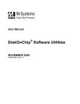
BLE Module User Manual
Features
Bluetooth version 4.0 BLE
Working frequency: 2.4GHz ISM band
Modulation method: GFSK (Gaussian Frequency Shift Keying)
RF Power: -23dbm, -6dbm, 0dbm, 6dbm (can be modified through AT Command AT+POWE)
Speed: Asynchronous: 1-6K Bytes
Synchronous: 1-6K Bytes
Security: Authentication and encryption
Service: Central & Peripheral UUID FFE0,FFE1
Power: +3.3VDC 50mA
No data byte limit for Send and receive
Long range: Open space have 100 Meters with iphone4s
Operating Current: In sleep mode 60uA~1.5mA, Active mode 8.5mA.
Working temperature: –5 to+65 Centigrade
Size: 18mm x 13.5mm x 2.2mm
No
Name
Description
CC2541
1
UART_RTS
UART interface
P1_5
2
UART_TX
UART interface
P1_6
3
UART_CTS
UART interface
P1_4
BLE Module User Manual
Page 1 of 24
4
UART_RX
UART interface
P1_7
5
NC
NC
P2_1
6
NC
NC
P2_2
7
NC
NC
PIN2
8
NC
NC
PIN3
9
VCC
V3.3
VCC
10
NC
NC or VCC
11
RESETB
Reset if low <100ms
RESET_N
12
GND
Ground
GND
13
PIO3
input/output pin
P1_1
14
PIO2
input/output pin/PWM
P1_0
15
PIO1
System LED
P0_7
16
PIO0
System KEY
P0_6
Sleep mode
Waking the module up from sleep mode
There are two ways to wake up module from sleep mode.
1. Send a string (Length > 80 bytes) e.g. “bla blaa blaaa blaa blaaa blaa blaaa bla blaa blaaa blaa
blaaa blaa blaaa bla blaa blaaa blaa blaaa blaa blaaa bla blaa blaaa blaa blaaa…..”
This string can wake the module up and you will receive “OK+WAKE” string through UART. Note:
The input string should not include any AT commands.
2. Pull pin PIO0 to Ground for at least 1 second then pull it back to +3.3V
Note: MangoCube BLE has this pin connected to+3.3V.
After waking up the module, you can send and receive AT commands.
Putting the module into sleep mode
In discoverable stage, send “AT+SLEEP” string through UART, if all is okay, the module will return
“OK+SLEEP” string and will go into sleep mode.
BLE Module User Manual
Page 2 of 24
System KEY (PIO0) function description
Pull pin PIO0 to Ground for at least 1 second then pull it back to +3.3V. The module will have one of the
following responses;
1.
If Module is in sleep mode;
Module will wake up immediately, if AT+NOTI value is “1”, module will send “OK+WAKE” string
through UART.
2. If Module has already connected to remote device;
Module will disconnect from remote device.
3. If Module is in standby mode;
Module will reset to default configuration. Then restart.
System LED (PIO1) function description
LED is turned off
: Module is off or in sleep mode.
LED is blinking (High for 500 ms, Low for 500 ms): Module is powered on but not connected to other
device.
LED is on (solid)
: Module is connected to other device.
Working Modes
Mode 0 (Transmission mode)
By default the module works in Transmission mode. When the module is not in AT
command/configuration stage, it can transfer the data to connected device using serial connection.
Mode 1(PIO acquisition mode)
In this mode the module can acquire input state of pins PIO2 and 3.
Mode 2(Remote control mode)
In this mode the module can output state of pins PIO2 and 3.
Role
•
•
Peripheral
Control
A Peripheral device can advertise, to let other devices know that it is there, but it is only a Central device
that can actually send a connection request to establish a connection.
BLE Module User Manual
Page 3 of 24
Default Setting
AT Commands
Name: MangoCube BLE; Baud: 115200, N, 8, 1; Pin code: 000000; Peripheral Role; transmit mode.
AT Command format
Uppercase AT command format in string, without any other symbol. (e.g. \r or \n).
e.g. AT+Command
AT commands
1. Test command/ AT command mode
Send
Receive
Parameter
AT
OK
None
OK+LOST
If Module is not connected to remote device, it will receive: “OK”
If Module has connected, module will disconnected from remote device and if “AT+ NOTI” is setup to 1,
it will receive: “OK+LOST”
2. Query module address
Send
AT+ADDR?
Receive
OK+ADDR:MAC Address
Parameter
None
3. Query/Set Advertising interval
Send
AT+ADVI?
Receive
Parameter
OK+ Get:[Para]
None
BLE Module User Manual
Page 4 of 24
AT+ADVI[Para]
OK+ Set:[Para]
Para: 0 ~ F
0: 100ms
1: 152.5 ms
2: 211.25 ms
3: 318.75 ms
4: 417.5 ms
5: 546.25 ms
6: 760 ms
7: 852.5 ms
8: 1022.5 ms
9: 1285 ms
A: 2000ms
B: 3000ms
C: 4000ms
D: 5000ms
E: 6000ms
F: 7000ms
Default: 0
4. Query/Set Advertising Type
Send
Receive
Parameter
AT+ADTY?
OK+ Get:[Para]
None
AT+ADTY[Para]
OK+ Set:[Para]
Para: 0 ~ 3
0: Advertising,
Scan Response,
Connectable
1: Only allow last device
connect in 1.28 seconds
2: Only allow Advertising
and Scan Response.
3: Only allow Advertising
Default: 0
BLE Module User Manual
Page 5 of 24
5. Query/Set ANCS switch
Send
Receive
Parameter
AT+ANCS?
OK+ Get:[Para]
None
AT+ANCS[Para]
OK+ Set:[Para]
Para: 0 ~ 1
0: Off
1: On
Default: 0
Note1: Please send AT+RESET to restart the module if you set the value to 1.
Note2: Must execute AT+TYPE3 at first.
6. Query/Set whitelist switch
Send
Receive
Parameter
AT+ALLO?
OK+ Get:[Para]
None
AT+ALLO[Para]
OK+ Set:[Para]
Para: 0 ~ 1
0: Off
1: On
Default: 0
Note: White List allows three mac addresses to be linked to module. Please use AT+AD command to
set whitelist mac address.
7. Query/Set whitelist mac address
Send
Receive
Parameter
AT+AD[para1]??
OK+ Get:[Para2]
None
AT+ALLO[Para1][Para2]
OK+ Set:[Para2]
E.g. Send
Receive
Para1: 1, 2, 3
Para2: MAC address
: AT+ID1001122334455
: OK+Set:001122334455
8. Query/Set Module pin output state, after power supplied
Send
AT+BEFC?
Receive
Parameter
OK+ Get:[Para]
None
BLE Module User Manual
Page 6 of 24
AT+BEFC[Para]
OK+ Set:[Para]
Para: 000~ 3FF
Default: 000
3FF == 001111111111, left to right side is map to PIO0~PIOB, PIO0 and PIO1 is used by system. Only
PIO2~PIOB pins is available.
e.g. Set PIO2~PIOB all output HIGH after power up.
Send
: AT+BEFC3FF
Receive
: OK+Set:3FF
When next time power up, the module will output HIGH on PIO2~PIOB.
Note: Query PIO pins current state please use AT+PIO?? command.
Note: Please don’t use this command when “AT+MODE1” is setup.
9. Query/Set Module pin output state, after connection is established
Send
Receive
Parameter
AT+AFTC?
OK+ Get:[Para]
None
AT+AFTC[Para]
OK+ Set:[Para]
Para: 000~ 3FF
Default: 000
3FF == 001111111111, Left to right side is map to PIO0~PIOB, PIO0 and PIO1 is used by system. Only
PIO2~PIOB pins is available.
e.g. Set PIO2~PIOB all output high when connection is established.
Send
: AT+AFTC3FF
Received
: OK+Set:3FF
When Bluetooth connection is established, module PIO2~PIOB will output high.
Note: Query PIO pins current state please use “AT+PIO??” command.
Note: Please don’t use this command when “AT+MODE1” is setup.
10. Query/Set battery monitor switch
Send
Receive
Parameter
AT+BATC?
OK+ Get:[Para]
None
AT+BATC[Para]
OK+ Set:[Para]
BLE Module User Manual
Para: 0 ~ 1
0: Off
1: On
Default: 0
Page 7 of 24
11. Query battery information
Send
Receive
Parameter
AT+BATT?
OK+BATT:[Para]
Para: 000~100
There are two ways to get battery information:
a. Before establishing a connection, Send “AT+BATT?” through UART.
b. After establishing a connection, in Mode 1 or 2, remote side send “AT+BATT?”
Battery information has included in scan response data package, one hour update once. You can use
Android or IOS discovery module, when module has been discovered, you can get it from scan result
array.
12. Query/Set Bit format
Send
Receive
AT+BIT7?
OK+Get:[para1]
AT+BIT7[para1]
OK+Set:[para1]
Parameter
Para1: bit7 switch.
0-----Not compatible
1-----Compatible
Default: 0
This command is used only for compatible uses 7 data bits, 2 stop bit device.
13. Query/Set baud rate
Send
Receive
AT+BAUD?
OK+Get:[para1]
AT+BAUD[para1]
OK+Set:[para1]
Parameter
Para1: Baud rate No.
0---------9600
1---------19200
2---------38400
3---------57600
4---------115200
5---------4800
6---------2400
7---------1200
8---------230400
Default: 0(9600)
e.g.
Query baud:
Send: AT+BAUD?
BLE Module User Manual
Page 8 of 24
Receive: OK+Get:0
Setup baud:
Send: AT+BAUD1
Receive: OK+Set:1
Note: If set to Value 7, after next power up, the module will not support any AT Commands, until
PIO0 is pressed, Module will change Baud to 9600.
14. Query/Set Characteristic
Send
Receive
Parameter
AT+CHAR?
OK+Get:[para1]
Para1: 0x0001~0xFFFE
AT+CHAR[para1]
OK+Set:[para1]
Default: 0xFFE1
e.g. change characteristic value to 0xAAA0
Send
: AT+CHAR0xAAA0
Received
: OK+Set:0xAAA0
15. Clear Last Connected device address
Send
Receive
Parameter
AT+CLEAR
OK+CLEAR
None
Notice: Only Central role is used.
16. Try connect to last succeeded device
Send
Receive
AT+CONNL
OK+CONN[Para1]
Parameter
Para1: L, E, F, N L:
Connecting
E: Connect error
F: Connect Fail
N: No Address
Notice: Only Central role is used. Must set up AT+IMME1 and AT+ROLE1 first.
If remote device has already connected to other device or shut down, “OK+CONNF” will be received
after about 10 seconds.
BLE Module User Manual
Page 9 of 24
17. Try connecting an address
Send
Receive
AT+CO[P0][P1]
OK+CO[P0][P0][P2]
Parameter
P0: N, 1
N: Normal Address
1: Dual module Addr
P1: Address
Like: 0017EA090909
P2: A, E, F
A: Connecting
E: Connect error
F: Connect Fail
Notice: Only central role is used. Must set up AT+IMME1 and AT+ROLE1 first.
If remote device has already connected to other device or shut down, “OK+CONNF” will received
after about 10 Seconds.
e.g. Try to connect an device which MAC address is 00:17:EA:09:09:09
Send: AT+CON0017EA090909
May receive a reply:
OK+CONNA
OK+CONNE
OK+CONN
OK+CONNF
=========
=========
=========
=========
Accept request, connecting
Connect error
Connected, if AT+NOTI1 is setup
Connect Failed, after 10 seconds
18. Query PIO02~PIO03 input (output) state
Send
AT+COL??
Receive
OK+ Col:[Para1]
Parameter
Para1: 0x00~0xFF
Para1 is a byte, has 8 bits, bit 7 ~ bit 0 is map to the PIO4 ~ PIO11.
19. Query/Set PIO collection rate
Send
AT+CYC??
Receive
OK+ Get:[para1]
BLE Module User Manual
Parameter
Para1: 00~99
Page 10 of 24
AT+CYC[para1]
OK+ Set:[para1]
Unit: seconds
Default: 10
In mode 1, when PIO state is changed, module will send OK+Col:[xx] to UART or remote side. This
command is set send interval.
20. Start a device discovery scan
Send
Receive
AT+DISC?
OK+DIS[P0][P1]
Parameter
P0: C,0, 1, 2
C: Common string
0~2: Address type
P1: S, E, [MAC String]
S: Start discovery
E: End discovery
MAC String :
Device MAC string
Note: Please set AT+ROLE1 and AT+IMME1 first.
e.g.
Send
: AT+DISC?
Received
: OK+DISCS
Received
: OK+DIS[P0]:123456789012 (discovered device address information) If AT+SHOW1 is
setup, you will receive then Name information as follow
Received
: OK+NAME: xxx
After send Name value, will send two extra “\r\n” value ASCII byte
Received
: OK+DIS[P0]:234567890123
Received
: OK+NAME: xxx
After send Name value, will send two extra “\r\n” value ASCII byte (Before V535 max results is 6, Since
V535 not limit)
Received
: OK+DISCE
Connect use array index:
Connect to a discovered device: AT+CONN0, AT+CONN1……AT+CONN5
Connect use MAC string: AT+CON[MAC String]
BLE Module User Manual
Page 11 of 24
21. Connect to a Discovered device
Send
Receive
AT+CONN[para1]
OK+CONN[para2]
Parameter
Para1: 0~5
Para2: E, F, 0~5
0~5: Try to connect
E: Link error
F: Link failed
0~5: Try to connect
This command is use after execute AT+DISC? This command will clear all discovery data.
22. Query/Set iBeacon deploy mode
Send
AT+DELO[para1]
Receive
OK+DELO[para1]
Parameter
Para1: 1, 2
1: Allowed to broadcast
and scanning
2: Only allow broadcast
After receive OK+DELO[para1], module will reset after 500ms. This command will let module into nonconnectable status until next power on.
23. Remove bond information
Sen
AT+ERASE
Receive
Parameter
OK+ERASE
24. Set advertising data FLAG byte
Send
AT+FLAG[P1]
Receive
OK+ Set:[P1]
Parameter
P1: 0~FF (one byte)
Note: This command added in V530. Please refer to AT+BATT? command.
25. Query/Set flow control switch
Send
AT+FIOW?
Receive
OK+ Get:[para1]
BLE Module User Manual
Parameter
Para1: 0, 1
Page 12 of 24
AT+FIOW[para1]
OK+ Set:[para1]
0: Off
1: On
Default: 0
26. Query/Set module RX gain
Send
Receive
AT+GAIN?
OK+ Get:[P1]
AT+GAIN[P1]
OK+ Set:[P1]
Param
P1: 0, 1
0: No RX gain
1: Open RX gain
Default: 0
Note: This command is added since V535
27. System Help Information
Send
Receive
Parameter
AT+HELP?
Help Information
None
28. Query/Set Module work type
Send
Receive
AT+IMME?
OK+ Get:[para1]
AT+IMME[para1]
OK+ Set:[para1]
Param
Para1: 0, 1
1: When module is
powered on, only respond
to the AT Command.
Don’t do anything. Until AT
+ START, AT+CON,
AT+CONNL commands is
received.
0: When power on, work
immediately
Default: 0
Note: This command is only used for Central role.
BLE Module User Manual
Page 13 of 24
29. Query/Set Module iBeacon switch
Send
Receive
Parameter
AT+IBEA?
OK+Get:[para1]
Para1: 0, 1
AT+IBEA[para1]
OK+Set:[para1]
0: Turn off iBeacon
1: Turn on iBeacon
Default: 0
iBeacon UUID is: 74278BDA-B644-4520-8F0C-720EAF059935.
30. Query/Set iBeacon UUID
Send
Receive
AT+IBE0?
OK+Get:[para1]
AT+IBE0[para1]
OK+Set:[para1]
Parameter
Para1: 00000001~
FFFFFFFE
Default: 74278BDA
iBeacon UUID is: 74278BDA-B644-4520-8F0C-720EAF059935. This command can change red colour
string in iBeacon UUID.
e.g. Send: AT+IBE012345678 change iBeacon UUID red colour string to “12345678”
31. Query/Set iBeacon UUID
Send
Receive
AT+IBE1?
OK+Get:[para1]
AT+IBE1[para1]
OK+Set:[para1]
Parameter
Para1: 00000001~
FFFFFFFE
Default: B6444520
iBeacon UUID is: 74278BDA-B644-4520-8F0C-720EAF059935. This command can change red colour
string in iBeacon UUID.
e.g. Send: AT+IBE112345678 change iBeacon UUID red colour string to “12345678”
32. Query/Set iBeacon UUID
Send
Receive
Parameter
AT+IBE2?
OK+Get:[para1]
AT+IBE2[para1]
OK+Set:[para1]
Para1: 00000001~FFFFFFFE
Default: 8F0C720E
BLE Module User Manual
Page 14 of 24
iBeacon UUID is: 74278BDA-B644-4520-8F0C-720EAF059935. This command can change red colour
string in iBeacon UUID.
e.g. Send: AT+IBE112345678 change iBeacon UUID red colour string to “12345678”
33. Query/Set iBeacon UUID
Send
Receive
AT+IBE3?
OK+Get:[para1]
AT+IBE3[para1]
OK+Set:[para1]
Parameter
Para1: 00000001~
FFFFFFFE
Default: AF059935
iBeacon UUID is: 74278BDA-B644-4520-8F0C-720EAF059935. This command can change red colour
string in iBeacon UUID. This command is added since V520 version.
e.g.: Send: AT+IBE112345678 change iBeacon UUID red colour string to “12345678”
34. Query/Set Module iBeacon Major version
Send
Receive
AT+MARJ?
OK+Get:[para1]
AT+MARJ[para1]
OK+Set:[para1]
Parameter
Para1: 0x0001, 0xFFFE
Default: 0xFFE0
e.g. Change major version to 0x0102
Send: AT+MARJ0x0102, if all is okay, module will send back OK+Set:0x0102
35. Query/Set Module iBeacon minor
Send
Receive
AT+MINO?
OK+Get:[para1]
AT+MINO[para1]
OK+Set:[para1]
Parameter
Para1: 0x0001, 0xFFFE
Default: 0xFFE1
36. Query/Set Module iBeacon Measured power
Send
Receive
AT+MEAS?
OK+Get:[para1]
AT+MEAS[para1]
OK+Set:[para1]
BLE Module User Manual
Parameter
Para1: 0x0001, 0xFFFE
Default: 0xFFE1
Page 15 of 24
37. Query/Set Module Work Mode
Send
Receive
Parameter
AT+MODE?
OK+Get:[para1]
Para1: 0, 1, 2
AT+MODE[para1]
OK+Set:[para1]
0: Transmission Mode
1: PIO collection Mode +
Mode 0
2: Remote Control Mode
+ Mode 0
Default: 0
Mode 0:
Before establishing a connection, you can use the AT command to configure the module through UART.
After establishing a connection, you can send data to remote side from each other.
Mode 1:
Before establishing a connection, you can use the AT command configuration module through UART.
After established a connection, you can send data to remote side. Remote side can do the followings:
Send AT command configuration module.
Collect PIO03 pins input state.
Remote control PIO2 pin output state.
Send data to module UART port (not include any AT command and per package must less than 20
bytes).
Mode 2:
Before establishing a connection, you can use the AT command to configure the module through
UART.
After established a connection, you can send data to remote side. Remote side can do fellows:
Send AT command configuration module.
Remote control PIO2, PIO3 pins output state.
Send data to module UART port (not include any AT command and per package must less than 20
bytes).
38. Query/Set Notify information
Send
Receive
AT+NOTI?
OK+Get:[para1]
BLE Module User Manual
Parameter
Para1: 0, 1
Page 16 of 24
AT+NOTI[para1]
OK+Set:[para1]
0: Don’t Notify
1: Notify
Default: 0
If this value is set to 1, when link established or lost the module will send OK+CONN or OK+LOST
string through UART.
39. Query/Set notify mode
Send
Receive
Q: AT+NOTP?
OK+ Get[P1]
Q: AT+NOTP[P1]
OK+ Set[P1]
Parameter
P1: 0, 1; default: 0
0: without address
1: with address
This command must work with “AT+NOTI1”, if this switch is open, when the module connects, the
prompt string will include the remote address.
OK+CONN: 001122334455 String “001122334455” is the MAC address string
40. Query/Set Module name
Send
AT+NAME?
AT+NAME[para1]
Receive
OK+NAME[para1]
OK+Set[para1]
Parameter
Para1: module name,
Max length is 12.
Default: Mangocube
e.g. change module name to MyName
Send :
AT+NAMEMyName
Receive : OK+SetName:MyName
41. Query/Set output driver power
Send
Query: AT+PCTL?
Receive
Parameter
OK+Get:[para1]
None
BLE Module User Manual
Page 17 of 24
Set: AT+PCTL[para1]
OK+Set:[para1]
Para1: 0,1
0:Normal power output
1:Max power output
Default: 1
Note: Added in V527
42. Query/Set Parity bit
Send
Receive
Parameter
Query: AT+PARI?
OK+Get:[para1]
None
Set: AT+PARI[para1]
OK+Set:[para1]
Para1: 0,1,2
0:None
1:EVEN
2:ODD
Default: 0 (None)
43. Query/Set PIO1 output status (System LED)
Send
Receive
Parameter
AT+PIO1?
OK+Get:[para1]
AT+ PIO1 [para1]
OK+Set:[para1]
Para1: 0, 1
0: Unconnected Output
500ms High 500ms Low,
Connected output High.
1: Unconnected output
Low, Connected output
High.
Default: 0
44. Query/Set PIO pins output high or low (Only this time, when module next
power on, this value is not be used)
Send
Receive
AT+PIO[para1]?
OK+PIO:[para1][para2]
BLE Module User Manual
Parameter
Para1: 2~3, ?
Page 18 of 24
AT+PIO[para1][para2]
OK+PIO:[para1][para2]
Para2: 0, 1, ?
MangoCube BLE has only
has 4 pins. Para1 is which
PIO pin you want to
Query/Set
Value: 2,3.
Para2 is Query or setup
value.
“0” is low and “1” is high
and “?” is query
e.g. To Query PIO2,
Send: AT+PIO2?
To Setup PIO2 output high,
Send
: AT+PIO21
Receive : OK+PIO21
MangoCube BLE version: para1 value is 2, 3
V525 added PIO2 PWM function, Para2 value is 0~9
0: output low
1: output high
2: output 100ms PWM
3: output 200ms PWM
……
9: output 800ms PWM
V527 added AT+PIO?? Format query all pins output state.
45. Query/Set Pin Code
Send
Receive
AT+PASS?
OK+Get:[para1]
AT+PIN[para1]
OK+Set:[para1]
BLE Module User Manual
Parameter
Para1 is Pin Code,
000000~999999
Default: 000000
Page 19 of 24
e.g. To Query Pin Code,
Send
:
AT+PIN?
Receive : OK+PIN:000000
To Setup Pin Code 001234
Send
: AT+PIN001234
Receive : OK+Set:001234
46. Query/Set Module Power
Send
Receive
Parameter
AT+POWE?
OK+Get:[para1]
None
AT+ POWE [para1]
OK+Set:[para1]
Para: 0 ~ 3
0: -23dbm
1: -6dbm
2: 0dbm
3: 6dbm
Default: 2
47. Query/Set Module sleep type
Send
Receive
Parameter
AT+PWRM?
OK+Get:[para1]
None
AT+PWRM[para1]
OK+Set:[para1]
Para1: 0~1
0:Auto sleep
1:don’t auto sleep
Default: 1
Note: Only supports peripheral role.
48. Query/Set reliable advertising mode
Send
Receive
AT+RELI?
OK+ Get:[para1]
AT+RELI[para1]
OK+ Set:[para1]
Param
Para1: 0, 1
0: Normal advertising
1: Reliable advertising
Default: 0
Note: This command is added since V530
BLE Module User Manual
Page 20 of 24
49. Restore all setup value to factory setup
Send
Receive
Parameter
AT+RENEW
OK+RENEW
None
Send
Receive
Parameter
AT+RESET
OK+RESET
None
50. Restart module
51. Query/Set Master and Slaver Role
Send
Receive
Parameter
AT+ROLE?
OK+Get:[para1]
Para1: 0, 1
AT+ROLE[para1]
OK+Set:[para1]
0: Peripheral
1: Central
Default: 0
52. Query RSSI Value
Send
Receive
Parameter
AT+RSSI?
OK+RSSI:[para1]
None
Require: AT+MODE value > 0
Note: This command only used by Remote device to query when connected.
53. Query Last Connected Device Address
Send
AT+RADD?
Receive
OK+RADD:MAC Address
BLE Module User Manual
Parameter
None
Page 21 of 24
54. Query/Set Stop bit
Send
Receive
Parameter
AT+STOP?
OK+Get:[para1]
None
AT+STOP[para1]
OK+Set:[para1]
Para1:0, 1
0: One stop bit
1: Two stop bit
Default: 0 (One stop bit)
55. Work immediately
Send
Receive
Parameter
AT+START
OK+START
None
This command is only used when AT+IMME1 is setup.
56. Query Module into sleep mode
Send
Receive
Parameter
AT+SLEEP
OK+SLEEP
None
Note: Only support Peripheral role.
57. Query/Set save Module connected address parameters
Send
Receive
Parameter
AT+SAVE?
OK+Get:[para1]
None
AT+SAVE[para1]
OK+Set:[para1]
Para1: 0~1
0:Save when connected
1:Don’t Save
Default: 0
58. Query/Set discovery parameter
Send
Receive
Parameter
AT+SHOW?
OK+Get:[para1]
None
BLE Module User Manual
Page 22 of 24
AT+SHOW[para1]
OK+Set:[para1]
Para1: 0~1
0:Don’t show name
1:Show name
Default: 0
Note: Please execute AT+FILT0 first. If AT+SHOW1 is setup, AT+DISC? Command will show you the
name information included into scan result package.
59. Query/Set module connect remote device timeout value
Send
Receive
Parameter
AT+TCON?
OK+TCON:[para1]
None
AT+TCON[para1]
OK+Set:[para1]
Para1 is timeout value.
When time out t h e
module will not connect to
this address anymore, then
enter search mode.
Para1 allowed value:
000000~999999
Unit is ms.
Default: 000000 Connect
forever
This value is only used for Central Role, when module has Last Connected address.
60. Query/Set Module Bond/Security Mode
Send
Receive
Parameter
AT+TYPE?
OK+Get:[para1]
None
AT+TYPE[para1]
OK+Set:[para1]
Para1: 0~2
0:Not need PIN Code
1:Auth not need PIN
2:Auth with PIN
3:Auth and bond
Default: 0
BLE Module User Manual
Page 23 of 24
61. Query/Set service UUID
Send
Receive
AT+UUID?
OK+Get:[para1]
AT+UUID[para1]
OK+Set:[para1]
Parameter
Para1: 0x0001~0xFFFE
Default: 0xFFE0
e.g. Change UUID value to 0xAAA0,
Send : AT+UUID0xAAA0
Receive : OK+Set:0xAAA0
62. Query Software Version
Send
Receive
Parameter
AT+VERR?
Version Information
None
BLE Module User Manual
Page 24 of 24