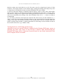
1
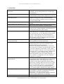
HV_User_Manual_2_8.doc 19. April. 2014 User Manual Rev. 2.8 Model Numbers HV 50-16, HV 200-2, HV 200-8, HV 200-16, HV 400-8, HV400-16, HV 500-8, HV 500-12, HV 500-16, AMP-HV 500, HV 500-16 b/a, HV 1000-8, HV 2000-8 www.stahl-electronics.com HV Series Installation and User Manual, Rev 2.8 TABLE OF CONTENTS 1. Safety Hints ………………………………….…………………………………… 3 2. General Information and Overview………………….………………………….. 2.1 Purpose and Description of the Device…………………………….. 2.2 Functional Principle and Block Diagram…………………………. 2.3. Device Variety……………………………………………………… 4 4 4 5 3. Installation ……………………………………………………………………..… 6 3.1. 3.2. Mechanical and Electrical Installation……………………………… Software Installation……………………………………………… .. 3.2.1 USB-Driver…………………………………………………. 3.2.2 LabVIEWTM control program………………………………. 4. Operation and Control Elements ……………………………………………….. 4.1 4.2 4.3 4.4 6 7 7 9 11 Elements on the front plate………………………………………… Control Software…………………………………………………… Output Characteristics……………………………………………… Switching the device off …………………………………………… 11 12 15 16 5. Using the Floating Ground Option……………………………………………… 17 6. Maintenance………………………………………….…………………………. 19 7. Specifications……………………………………………………………………. 20 Appendix…………………………………………………………………………… 22 User-Defined Remote-control and List of Commands ……………… 22 Version AMP-HV………………………………………………………….. 25 Declaration of Conformity ………………………………………………………… 26 2 www.stahl-electronics.com phone: +49 6242-504882, fax: +49 6242 504884 HV Series Installation and User Manual, Rev 2.8 1. Safety Hints Read all installation, operation, and safety instructions Rear side switch turns device completely off This equipment must be connected to an earth safety ground Do not modify the unit Change cabling only when device is off Do not operate in wet/damp conditions Beware of external magnetic fields Service is to be performed by qualified service persons only Do not block chassis ventilation openings Operate carefully with respect to risk of electrical shock Routinely cleaning from dust No outdoor operation Prior to operation, thoroughly review all safety, installation, and operating instructions accompanying this equipment. If the device is not in use for a longer time, it is recommended to turn the mains switch at rear side off. This product is grounded through the grounding conductor of the power cord. To avoid electrical hazard, the grounding conductor must be connected to protective earth ground. Do not make electrical or mechanical modifications to this unit. Changing the cabling, when voltages are present at the outputs can lead to formation of harmful sparks. To avoid electric shock hazard, do not operate this product in wet or damp conditions. Protect the device from humidity and direct water contact. External magnetic fields can impair, damage or even destroy this device. A maximum external field strength of no more than B = 5mT is admissible. Having placed the device at any time into an external magnetic of bigger B = 5mT (regardless if power was turned on or off) can lead to severe overheating of the device and severely increased hazard of fire. All servicing on this equipment must be carried out by factory-qualified service personnel only. Slots and openings in the chassis are provided for ventilation purposes to prevent overheating of the equipment and must not be restricted. All 4 case vents should continuously be cleared (fan inlet at rear side, air outlet at rear and top side), in order to prevent overheating. If mounted in a rack, please allow 2cm clearance at the top cover with respect to the next device above. If in doubt about the sufficiency of air ventilation, provide a software readout of the internal temperature sensor for regular inspection, e.g. every 2 minutes. A temperature over 45°C indicates inadequate air ventilation. This device can produce a voltage up to +/-500VDC at its output lines, which is harmful in case of direct touch with the human body. This voltage may be even exceeded, in case that an additional external voltage is applied to the “floating GND” input, the device is shut off before disabling the outputs, or an internal failure occurs. Care must be taken to avoid unintentional touching of any output line to the human body or any devices which might be endangered by high voltages. After long operation, or operation in a dusty environment it is strongly recommended to have the internal parts of the device cleaned by the manufacturer, or an appropriately qualified workshop in order to reduce the hazard of overheating. Outdoor operation of the device is not admissible. 3 www.stahl-electronics.com phone: +49 6242-504882, fax: +49 6242 504884 HV Series Installation and User Manual, Rev 2.8 2. General Information and Overview 2.1 Purpose and Description of the Device Purpose of the HV series devices is the supply of stable DC voltages (+/-50V up +/- 500V or 1000V, model depending) for electrostatic lenses, beam deflectors or ion traps. Unlike DC power supplies, the outputs currents are limited to small values only, and the outputs are optimized for very high short and long term stability, low ripple, low noise and low temperature drift. The HV Series devices are housed in standard 19-inch rack-mount cases. User control of the device can be accomplished by PC control programs, utilizing a standard USB connection (USB 2.0 compatible) as hardware link. A LabVIEWTM control program is provided by the manufacturer for this purpose. An unique feature is the combination of multiple channels and the continous zero crossing capability, giving the user the possibility to sweep from positive (e.g. +400V) to negative (e.g. -400V) voltages (or vice versa) continuously without switches and voltage breaks. (Note, the 1000V version has not bipolar, but unipolar and reversable polarity). The bipolar versions use a unique bipolar output stage. They feature a true 4-quadrant sink/source capability and can deliver/take electrical currents both ways disregarding the output voltage polarity. 2.2 Functional Principle and Block Diagram The following picture displays a block diagram of the internal structure and illustrates the functional principle. The control interface receives commands over the USB connection. The received parameters set the voltage values for every channel. The outputs can deliver a current up to the internally limited values. The standard setting is roughly +/-100µA limitation for every individual output channel (see section 4.3). If a channel voltage is changed, the internal regulation will try to establish the programmed voltage. If it does succeed to do so, the corresponding indicator (LED) on the right hand side of the front plate will lighten up green, in other cases or in an overload event, it will become red. In case the overload has been removed, it will lighten up green again. In case the option “floating GND” is installed, the device also provides the possibility to float the internal reference ground voltage, to which the voltage settings refer, with respect to the case- and protection GND. Applying an additional voltage to the “Offset GND” input will shift all output values with respect to the case ground. Any voltage on that input therefor places a common offset to the voltage values programmed by the user (see section 5). The HV series devices do not provide a measurement of this external offset. It is up to the user to determine its value. 4 www.stahl-electronics.com phone: +49 6242-504882, fax: +49 6242 504884 HV Series Installation and User Manual, Rev 2.8 Block Diagram: HV series devices 2.3. Device Variety The following devices are currently members of the HV series device family: Output voltage -50V … +50V 4 channels Output voltage -50V … +50V 8 channels Output voltage -50V … +50V 16 channels Output voltage -200V … +200V 2 channels Output voltage -200V … +200V 8 channels Output voltage -200V … +200V 16 channels Output voltage -400V … +400V 4 channels Output voltage -400V … +400V 8 channels Output voltage -400V … +400V 16 channels Output voltage -500V … +500V 8 channels Output voltage -500V … +500V 12 channels Output voltage -500V … +500V 16 channels Output voltage -1kV… 0 or 0…+1kV 4 channels, outputs unipolar, reversible Output voltage -1kV… 0 or 0…+1kV 8 channels, outputs unipolar, reversible Output voltage -2kV… 0 or 0…+2kV 8 channels, outputs unipolar, non-reversible HV 50-4 HV 50 HV 50-8 HV 50-16 HV 200-2 HV 200 HV 200-8 HV 200-16 HV 400-4 HV 400 HV 400-8 HV 400-16 HV 500-8 HV 500 HV 500-12 HV 500-16 HV 1000-4 HV 1000 HV 1000-8 HV 2000 HV 2000-8 HV QUAD 275-16 HV QUAD 8 pairs of unipolar complementary outputs with opposite polarity, 0…+/- 275V, or 0…+/-450V designed for electrostatic quadrupole lenses HV QUAD 450-16 HV Steerer Option AMP HV Steerer 250-16 HV Steerer 450-16 8 pairs of bipolar complementary outputs with opposite polarity, designed for electrostatic quadrupole lenses and steerer plates Analog inputs (BNC, -5V to +5V) additionally to digital control The devices with outputs up to 500V (vs. GND) are provided by default with BNC outputs at their rear side, the other variants with higher voltages have SHV connectors. Voltages are referenced to case ground, alternativly a “Floating Ground Option“ can be ordered, which allows floating the reference GND up to a specified floating voltage. 5 www.stahl-electronics.com phone: +49 6242-504882, fax: +49 6242 504884 HV Series Installation and User Manual, Rev 2.8 3. Installation 3.1. Mechanical and Electrical Installation Positioning: Provide sufficient air cooling of the device and locate in normal horizontal position to allow for defined air convection. Rack mounting into a standard 19” rack is as well possible as resting the device on a table. If mounted in a rack, please allow 2cm clearance at the top cover with respect to the next device above. All 4 case vents must permanently be cleared (fan inlet at rear side, air oulet at rear and top side), in order to prevent overheating. If in doubt about the sufficiency of air ventilation, provide a software readout of the internal temperature sensor for regular inspection, e.g. every 2 minutes. A temperature over 45°C indicates inadequate air ventilation. Keep air vents always cleared to ensure sufficient ventilation Beware of external magnetic fields: Strong external magnetic fields can impair, damage or even destroy this device (e.g. proximity to a superconducting magnet). A maximum external field strength of no more than B = 5mT is admissible. Not observing this important condition can lead to severe overheating of the device and increases the hazard of fire. Connecting to mains power: Connect the device to the mains power supply by using an appropriate power cord, being properly wired and providing a grounded outlet. The power cord must be suited with respect to possible load currents and be rated to 5A current. Please observe country depending mains voltage ratings. Cabling of voltage outputs: Always provide appropriate and safe cabling when connecting the device to other devices or vacuum/experimental setups. Cabling is prefered using high voltage cable with proper shielding. BNC or SHV connector cables are a suitable choice in order to ensure proper shielding against exernal noise pickup and in order to provide protective ground for safety reasons. Always be aware about the potential hazard of high electrical voltages to human beings and sensitive objects of all kind (see also safety hints in section 1). Please note, that wiring may only be done when the device is turned off. Connecting a powered output to external circuitry can easily cause sparks and electrical discharges. The resulting overvoltages can severely and permanently damage the device itself and also external circuitry. After the device has been switched off allow at least 2 minutes to pass until cabling is changed. USB connection: Use a standard type-A-B connection cable (USB 2.0 standard) to connect the device to the control computer. After connecting to a PC under Windows XP, the “Found New Hardware Wizard” should open (see next section for detailed description), regardless if the HV-Series device is already switched on or not, since the corresponding receiver inside the HV-Series device is powered by the USB bus itself and therefore autonomous. Cable length can be prolongated using an appropriate USB hub or repeater. 6 www.stahl-electronics.com phone: +49 6242-504882, fax: +49 6242 504884 HV Series Installation and User Manual, Rev 2.8 3.2. Software installation 3.2.1 USB-Driver The HV-Series devices use the USB bus for connecting to a control PC. Windows operating systems are assumed in the subsequent description. After proper cabling of the USB connection (see section before) the “Found New Hardware Wizard” under Windows should open up. Depending on the Windows version allow a few seconds to automatically identify the connected device and install drivers, or follow the described steps below. The automatic or manual installation will install the USB CDM drivers from FTDI, which is the manufacturer of the USB bus interface circuitry. The supplied installation CD provides suitable drivers for operation under Windows XP. In case FTDI drivers are already installed, a de-installation is recommended before a new re-installation with the latest diver version. Latest drivers, also for different other operating systems (Linux, Mac OS, other Windows versions) can be downloaded from http://www.ftdichip.com/FTDrivers.htm. Execute the following steps under Windows XP after automatic start of the “Found New Hardware Wizard”: The following screen opens up, in which you activate the last button “No, not this time” and continue with “Next”. In the following window choose “Install from a list or specific location” => “Next” 7 www.stahl-electronics.com phone: +49 6242-504882, fax: +49 6242 504884 HV Series Installation and User Manual, Rev 2.8 And afterwards you choose “Search for the best driver in these locations” and “Include this location in the search”. Browse now to the Installation CD and select the appropriate path with the USB drivers. Click “OK” and “Finish” to complete the first driver installation. After a few seconds the first window will show up again (“Found New Hardware Wizard”). This is because the driver comes in two separate parts, which both have to be installed. Go through the installation steps in the same way as before. After completion, the USB drivers are ready for use and indicate this by showing “HV Series: Device Ready” (or similar) in the lower right screen corner of your PC for a couple of seconds. Windows usually recommends to restart Windows now, but for immediate use of the HV-Series devices one can skip this point. Nevertheless the PC should be restarted at a later point and latest before installing any other piece of hardware or software. 8 www.stahl-electronics.com phone: +49 6242-504882, fax: +49 6242 504884 HV Series Installation and User Manual, Rev 2.8 3.2.2 LabVIEWTM control program Assuming that LabVIEWTM in Version 8.2 or higher is available on the target PC, copy the path containing the LabVIEWTM source code VI’s from the installation CD to a proper place of your choice on a local drive. By double-clicking on the file “HV-ControlPanel.vi” in the path “ui” (“User Interface”) the control panel for the HV Series devices will open, which can immediately be put into operation by clicking on the start-arrow in the upper left corner. See section below for more details about how to operate the control program. Executable version: In case that the LabVIEWTM development software in version 8.2 or higher is not available on the PC controlling the device, there is a second option. The so-called “LabVIEWTM run time engine” can be installed from the installation CD and the control program can be run subsequently. In this case modifications of the control software or implementation in own programs are not possible, but the completed software can be run unchanged in the version as it is. Please contact manufacturer for more details and possibilities, in case changes of the program are desired. To run the executable version, first install the LabVIEWTM Runtime Engine and follow the instructions. RuntimeEngine File Icon You will be requested to choose an installation directory and location for unzipping the required files. 9 www.stahl-electronics.com phone: +49 6242-504882, fax: +49 6242 504884 HV Series Installation and User Manual, Rev 2.8 As second step (in case not installed before on the respective PC) the National Instruments VISA drivers need to be installed, which enable the LabVIEWTM software RuntimeEngine File Icon accessing the PCs hardware resources. After completion of these two installations, the HV-Series control program can be run as executable file. Remark: One known problematic point with National Instruments drivers is the fact that they tend to collide sometimes with other drivers, especially for Tektronix oscilloscopes. If in doubt the other drivers should be temporarily removed and installed again. 10 www.stahl-electronics.com phone: +49 6242-504882, fax: +49 6242 504884 HV Series Installation and User Manual, Rev 2.8 4. Operation and Control Elements 4.1 Elements on the front plate power-on LED mains supply display switch switch LCD display LED indicators The front plate contains several control elements for the device. The device is powered up after turning on the rear-side mains supply switch and also the power button on the front plate. The Power-on-LED (green) indicates proper operation of the internal circuitry. A warning beeper will temporarily sound, which is used for ventilation fan monitoring. If the device is not in use, it is recommended to use the rear side mains switch to cut it completely off from mains supply. This is recommended in oder to minimize small supply currents which flow, when the the rear side switch is kept on, and also for safety reasons (e.g. overvoltages occasionally occuring on the mains supply line). The LCD display on the front side shows informations about received commands or the latest voltage settings for the output channels. It can be run in two modes: In the “Protocol Mode” all commands, which are received via the USB connection are listed, subsequently one after another. In the “Voltage Mode” all programmed voltages are listed, sorted by channels. Please observe, that the listed voltages refer to the reference ground, which might be floated if any non-zero voltage is applied to the “floating GND input”, and not referring to the case ground. The display modes are toggled by using the LCDdisplay switch on the front plate left besides the display. The actual output voltages, being read from from every individual channel, are also displayed right besides the programmed values. Please note that real output accuracy is much better than displayed on the LCD (see specifications in chapter 7). The front display voltage readings are rather understood as cross check of correct functionality than precision meters. Picture of LCD display in “Voltage Mode” The LCD display goes into power-save mode after roughly 60min with reduced background illumination. Any press on the display switch reactivates the backlight again. By toggling to the Protocol Mode the serial number of the device can be seen, and the number of the virtual COM port, under which the device is accessible from the PC user surface, as soon as communication with the controlling PC is established. The protocol mode also displays the elapsed operational hours of the device. This information is useful e.g. for deciding of routine exchange of the ventilation fan at the rear side. The display changes automatically to protocol mode, if any severe malfunction should occur. 11 www.stahl-electronics.com phone: +49 6242-504882, fax: +49 6242 504884 HV Series Installation and User Manual, Rev 2.8 The LED indicators on the right hand side of the device show the overload status of the individual output channels. Green Light = everything ok, no overload. Red Light = overload or error condition A LED will become red, when the programmed voltage cannot be held correctely at the respective output at the rear side. This can have several reasons. The most common are: 1. 2. 3. 4. There is a problem with the external circuitry, which is attached to the device, maybe a short cut to ground or short cut to another channel or other voltage supply by external cabling. Too much current is drawn from the output, e.g. because of heavy electrical leakage currents or discharges in vacuum. With heavy capacitive loads (e.g. micro-Farads) the output takes several seconds to built up the desired voltage. The LED should become green again after some seconds. An internal error appeared. The latter can be excluded, if the LED becomes green again after removing all external cabling. Contact manufacturer otherwise. Please note, that in case large voltage steps are programmed (e.g. from minimal voltage to maximum value in an instant) the indicator might become red for a short moment, since the output value will not instantaneously coincide with the programmed value. This is a regular behaviour. 12 www.stahl-electronics.com phone: +49 6242-504882, fax: +49 6242 504884 HV Series Installation and User Manual, Rev 2.8 4.2 Control Software After starting the LabVIEWTM main VI or application program the following user surface will appear, which can be operated in a mostly intuitive style. While starting up, a list of connected device (upper left corner) will appear and the program will list all recognized HV-Series devices inside this window. Please note that before making any change a device must be selected (clicking once by mouse) for further operation. picture shows a list with two recognized devices inside the displayed list. A mouse click selects the device to be changed. The information regarding the listed devices show: - device serial number (e.g.: HV015, for a HV-Series device with serial number 015) - the number of available channels on that specific device - the voltage rating (e.g. 400V) - the COM port number, under which the device will be accessible in Microsoft Windows from the PC. Note, that the USB driver on the PC will enumerate detected USB devices automatically. This COM port number may vary from PC to PC and does not depend on the connected HV- Series device itself. 13 www.stahl-electronics.com phone: +49 6242-504882, fax: +49 6242 504884 HV Series Installation and User Manual, Rev 2.8 In case a new device is connected to the PC while the program is already running, the list can be manually updated by pressing the button. In that case the software will check for possible new added devices and extend the list correspondingly. On the right hand side to the list of connected devices the user can set the voltages of each channel in the numerical control field, either manually by entering numbers or by clicking on the up/down arrows. A step size can be defined in the control field underneath the voltage controls. At right hand side besides the numerical control field for the voltages, the “Overload Status Indicators” appear. They are similar to the LEDs on the front plate and indicate the status of the regulation circuitry for every channel. As long as the user-set voltage can be held, the indicator is green, otherwise red. Routinely once per second the control program reads the actual status over the USB bus and updates the indicator colour. Nevertheless the standard automatic update rate of once per second could be slowed down by considerable CPU load or competing LabVIEWTM processes, working in parallel. A forced and immediate status check is provided if the user clicks on the button. After pressing the Options Button , the user can in the subsequent window manually read the device internal temperature or enter manually commands to the HV- Series device (recommended only for advanced users, see also the list of commands in the appendix). A click on the button brings all channels to zero voltage. Please allow a few seconds for all output to assume zero. Note that “zero” refers to the internal GND, which may float versus the case ground in case the “floating ground”option is installed. Note: Voltage Readback The actual voltages at the outputs can be read back by self-written programs using the corresponding ASCII command (see appendix). By default the readback values are not diplayed on the LabVIEW surface provided with the device. 14 www.stahl-electronics.com phone: +49 6242-504882, fax: +49 6242 504884 HV Series Installation and User Manual, Rev 2.8 4.3 Output Characteristics General properties The HV series devices feature precise and stable bipolar voltage outputs. With respect to the reference ground their voltage range is +/-50V (HV50), +/-200V (HV200), +/-400V (HV400), +/-500V (HV500), 0… +/-1000V (HV1000) or 0 … +2kV or -2kV with 4-quadrant sink or source capability and continuous crossing over zero voltage. The output lines assume the programmed voltage. Each channel can deliver up to the internally limited output currents (see also specifications in chapter 7). The purpose of the limitation is mainly to restrict currents to an amount, which is only minor harmful to external devices or human beings. Before using a channel, the user should ensure the completion of external cabling. It is not recommended to plug a HV cable, if the high voltage is already present: In case larger capacitive loads exists or an unintentional short cut to ground or any other voltage, high temporary electrical currents or gas discharges in air are able to damage the HV device severely or eventually other externally connected devices. Always finish cabling before turning the respective output channel on. The capacitive output load should not greatly exceed 100nF, to ensure stability. Higher loads can create instabilities, which may be noticed e.g. with a standard multimeter or an instable reading on the front plate. Resolution The outputs feature a stable setting of voltages with roughly 10mV resolution (2mV for model HV50xx), corresponding to an internal resolution of 16 Bits. Every output is equipped with a correction loop, which ensures low fluctuations and very good short term stability in order of a few ppm (see section 7 for further detailes). Output polarity HV 1000 In contrast to the HV 200 to 500 devices, which feature continous zero-crossing and truly bipolar outputs, the HV 1000 device requires manual switching of output polarity. The polarity is changed commonly for all outputs using a rear side switch (see photo below). Please be aware to change polarity ONLY if device is turned off and allow 10sec. to discharge internal capacitors. The switch features a lock to prevent unintentional switching. In order to change polarity first gently pull the switching lever and alter position subsequently. Do not use force to change the switch position. Settling time The outputs voltage settling time depends on the external load and is generally limited by the maximum voltage slope of roughly 2000V/sec. Under moderate loads the output will be accurate to better 0.1% of span in less than 5 sec., after any change of voltage on a certain channel. 15 www.stahl-electronics.com phone: +49 6242-504882, fax: +49 6242 504884 HV Series Installation and User Manual, Rev 2.8 Output accuracy, fluctuations and loads Generally the output accuracy is as specified in the technical data (see section 7). Precision components ensure a very good basic accuracy and very low long-term drift, both on a 10-4 level. A PID regulation loop on every individual output ensures very good stability and compensates for fluctuations from temperature-drifts or semiconductor-inherent low frequency noise. Intrinsic short term stability is therefore on the level of Millivolts, corresponding to only a few ppm’s (part per million) with respect to the full voltage span. All outputs feature protection resistors of 2.7kOhms serially to the internal output amplifiers (version HV 2000: 20kOhms), which will cause a voltage drop as soon as current is drawn from any output. Please take into account that voltage drop (according to Ohms law) for operation with considerable load currents or for high precision measurements. Note, that also Digital Multimeters draw a considerable current. E.g. 500V / 10MOhms = 50µA is drawn from a multimeter with 10 MOhm input resistance if a voltage of 500V is programmed. Loading the outputs with currents in the order of 100µA therefore should be avoided, if best possible precision is required. The capacitive output load should preferably not exceed 100nF (version HV 2000: smaller 10nF), to ensure stability. Higher loads can create instabilities, which can be noticed with a standard multimeter or an instable reading on the front plate display. Short cuts or other heavy loads at the outputs Generally all outputs are short-cut proof, with respect to GND-short cuts or short cuts to any voltage between the specified min./max. voltage (e.g. +/-500V for a HV 500 - xx device). Nevertheless suddenly occurring short cuts or overvoltages, for instance caused by sparks or other discharges represent a considerable hazard. Even though the outputs feature an internal protection circuitry, care should be taken to avoid any possibility to create overvoltages or heavy output current loads, in order to ensure a long life time. Also intentional short cuts at the outputs, e.g. caused by high voltage semiconductor switches are not admissible. In case a fast switch is placed at the output for switching purposes, a series resistance in the order of 1kOhm at the respective output is recommended to avoid excessive peak currents. Recovery from Overload If a overload conditions occurs (indicated by red LED light on the front plate), the outputs show a hysteresis behaviour, which means that the load has to be diminished to a certain amount below the overload threshold, or completely removed. This hysteresis is typically 10% of current limit or a few volts with respect to voltage. Allow the output overload detection circuitry 2-3 seconds to pass before indicating green light after the overload condition was removed. Error-Out Detection In devices starting from manufacturing year 2010 an additional output is provided at the rear side of the device, which delivers a logic 0V/5V level. When any PID loop for output regulation goes to saturation (corresponding LED on front plate getting red), this level becomes zero, +5V otherwise. 4.4 Switching the device off After switching the device off (from mains supply) the output voltages will assume ground potential. Let at least 20 sec. pass (U.S. variants: 3 minutes), in order to allow the voltages to fade out, before changing the cabling or touching any bare output line by hand. Beware of voltages on the Offset-GND line (in case the floating ground option is installed), since the latter is also fed to the output lines. 16 www.stahl-electronics.com phone: +49 6242-504882, fax: +49 6242 504884 HV Series Installation and User Manual, Rev 2.8 In general it is recommended to use the rear side mains switch, in order to completely separate the device from external supply. 5. Using the Floating Ground Option (not available for version with analog inputs like HV-AMP or 500-16 b/a or HV 1000) In case the option for floating ground is installed, the user has the possibility to float the reference ground to a certain amount with respect to the case of the device and shielding ground of the attached SHV cables (BNC cables). Please note, that the voltage settings given from the control program refer always to the local reference ground only. The absolute value of voltage at any output with respect to the case ground is therefore given by the sum of the externally applied voltage at the floating ground input and the programmed value, as mentioned above. The device does not measure the externally applied voltage and does not display its value. Any voltage on the “floating GND/Offset GND” input places therefore a common offset to all of the voltage values, which are programmed by the user: UOUT,i = Uprogrammed,i + Ufloating input where UOUT,i Uprogrammed,i Ufloating input means the real output voltage referred to case and protection ground (= shield of SHV/BNC cable) on output number i means the programmed value for output number i, and means the voltage applied by the user to the floating GND input. Please note that if there is no intention to commonly shift the output values by using the Offset-GND input, the respective BNC-plug must be shorted (with a short-cut plug) or terminated with 50 Ohms in order to define the commonly added voltage to zero. In case there is no such termination, correct functionality of the device is not obtained. The stability of the externally applied voltage and its dependencies on loads has to be taken into account, for considering output stability and precision of the output voltages, if they are measured versus case ground. The external voltage adds up with the respective values of the HV device, and 17 www.stahl-electronics.com phone: +49 6242-504882, fax: +49 6242 504884 HV Series Installation and User Manual, Rev 2.8 therefore voltage errors and drifts do as well. The same is true for voltage drops because of finite resistances: The output resistance of the external supply, feeding the floating ground input, may cause a voltage drop, if considerable currents are drawn through the HV Series outputs. As shown in the block diagram, a stabilizing capacitor (approx. 47nF to 2.2µF) at the “Offset GND” input provides already a reasonable amount of short term stabilisation in the order of seconds. Please note, that any voltage source, applied to the floating ground input, must have a current limitation in order not to potentially cause damage. Note, that a limitation value of Imax = +/-25mA or smaller is recommended. An overvoltage protection at that input line inside the HV Series device provides limitation to +/360VDC versus case ground (unless specified otherwise). The user should not exceed the rated offset voltage at this input. The isolation resistance of the floating GND versus the common GND (case GND) is typically larger 5GOhm, eventually diminished by an discharge resistor installed as noted on the rear side of the device (typ. 50M to 1G). Turning the device off (floating ground usage): Attention: in case an external voltage is supplied to the floating GND input, ensure to discharge the latter after usage or wait at least 5 minutes (after disconnecting the floating GND input cable) to prevent electrical shock in case leads connected to the device outputs will be accessible. 18 www.stahl-electronics.com phone: +49 6242-504882, fax: +49 6242 504884 HV Series Installation and User Manual, Rev 2.8 6. Maintenance The HV Series Voltage Source is designed for years of reliable operation. Under normal operating conditions, it should not require electrical maintenance, except routine cleaning of dust. Exchange of ventilation fan is strongly recommended every 50’000 operation hours (see below). If any question should arise, please contact the manufacturer. Routine cleaning All ventilation openings – top, bottom, sides, and rear panel – should be checked periodically and kept free of dust and other obstructions. A vacuum cleaner may be used to clean these vents when the unit is powered off. Do not use compressed air to clear the vents. The front panel may be cleaned periodically with a clean cloth and mild alcohol solution, when the unit is powered off. It is recommended to send the device to the manufacturer routinely in 2-year intervals for internal cleaning from dust. Calibration Under normal operating conditions, the HV Series Voltage Source will not require regular calibration. However, it can be returned to factory for complete electrical and mechanical inspection and calibration purposes. Also, if required, a certificate can be issued for traceability. Contact manufacturer for additional information. Fan life time and temperature monitoring The air ventilation fan is a part which shows unavoidable deterioration in time. Exchange of this part is strongly recommended after 50’000 hours of operation. Please contact manufacturer for replacement. Complete failure can lead to overheating of the device. Several temperature fuses and other protection measures provide a certain degree of safety against fire hazard in this case. Nevertheless, it is strongly recommended to read out regularly the devices temperature by software means in order to monitor the devices internal temperature and therefore to ensure avoidance of damage to the device or fire hazard. The elapsed operational time can be checked in the protocol mode (see section 4) in case the corresponding software tool is installed. A warning sounder (beeper) will activate in case of low fan rotational speed (applies for HV devices from manufacturing date 12/2010 and later). Other devices can be upgraded with this feature on demand. Fire hazard Please note, that excessive accumulation of dust inside the case of the device can lead to overheating. This, together with possible discharges increases the risk of fire, caused by electrical sparks. Routinely cleaning the device from dust minimizes this risk. It is therefore recommended to send the device to the manufacturer routinely in 2-year intervals for internal cleaning from dust, or to have it cleaned by an accordingly qualified electronical workshop. Also air conditions containing oil mists (e.g. proximity to a vacuum pump or mechanical machines) place a severe danger, since inflammable substances could enter the device through the ventilation holes. If in doubt, cleaning by an accordingly qualified electronical workshop or the manufacturer is strongly recommended. An increased hazard of fire may also occur if the device has been (permanently or temporarily) located in proximity to a strong (e.g. superconducting) magnet. A maximum external field of B = 5mT is admissible. Decommissioning Decommissioning of the device is recommended after latest 130’000 hours of operation. Please contact manufacturer for appropriate waste disposal and observe applicable legal regulations. 19 www.stahl-electronics.com phone: +49 6242-504882, fax: +49 6242 504884 HV Series Installation and User Manual, Rev 2.8 7. Specifications HV 50-xx HV 200-xx Output Voltage Range Output Connectors DC Output Current HV 500-xx HV 400-xx HV 1000-xx -1000V… 0V or 0V…+1000V HV 2000-xx -2000V… +200V or -200V…+2000V HV 200 to 500 BNC (standard) or SHV (option) HV 1000, 2000 SHV (other on request) 0 up to ±400 µA guaranteed, max. +650µA, -1.6mA 0 up to ±100 µA guaranteed HV 50 HV 200 HV 500, HV400 HV 1000, 2000 Per device maximum possible current per output Output Fuse Sink/Source Capability Standard Reference Ground Output Specifications -50V … +50V continuous zero crossing -200V … +200V continuous zero crossing -500V … +500V continuous zero crossing -400V … +400V continuous zero crossing Floating (in case option is installed) Accuracy assuming Tambient = 21°C…26°C % of Setting, Related to full span Offset Error HV 200 to 1000 HV 50 HV 2000 Ripple (50Hz, 100Hz), HV 200, HV 500 HV 200-2 HV 50 HV 400 Ripple, 1000V, 2000V version Noise 1 Hz …10MHz 200V, 500V HV 200-2 HV 50 HV 400 Low Frequency Noise 0...1 Hz 200V, 500V versions HV 200-2, HV 400-8 HV 50 Noise 0…10MHz, 1000V, 2000V version Channel crosstalk (DC voltage change on any channel, influenced by any other channel) 0 up to ±70 µA guaranteed max. ±350 µA (HV200), ±300 µA (HV 400 to HV 2000) guaranteed +280µA, -500µA (HV 50) +200µA, -420µA (HV 200 to HV 1000) fuse 100mA per channel, in devices HV 50, 200, 500, 1000; no fuses in HV 400, HV500, HV 2000 from manufacturing date 2013 and later full 4 quadrant-operation of outputs except HV 1000 and HV 2000 variant All outputs share a common GND (= case ground) Optional Reference GND may float ±350V vs. GND of case, 500V, 1kV or 2kV . This parameter is specified separately for each device. Floating GND isolation resistance vs. common GND typ. > 5GOhm, eventually diminished by discharge resistor installed as noted on device (typ. 50M) typical maximum typical drift (see note 1) (see note 1) 0.015% 0.05% 0.002% per day 0.014% per year ±10mV ±1.5mV ±40mV ±100mV ±3.5mV ±200mV ±3mV per day ±1mV per day ±9mV per day 2.5 to 5mVpp 2mVpp 1mVpp 0.75mVpp 10mVpp 50mVpp 2mVrms 1mVrms 0.13mVrms 0.4mVrms 1.3mVrms 1.0mVrms < 0.3mVrms 9mVrms 1.2ppm 2.5ppm (HV 200 to 2000) (HV 200 to 2000) 2.5ppm 5.4ppm (HV 50) (HV 50) 20 www.stahl-electronics.com phone: +49 6242-504882, fax: +49 6242 504884 HV Series Installation and User Manual, Rev 2.8 Temperature Coefficient Setting Offset HV 200 to 1000 Offset HV 50 Offset HV 2000 +/-15ppm/K 1.5mV/K 1mV/K 6 mV/K +/-21ppm/K 4.5mV/K 2.5mV/K 20mV/K Digital built-in Voltmeters on LCD Screen, Front Plate Accuracy of Voltmeter: Scale error Offset error Fluctuations typical 0.1% 0.1V 0.2Vpp 0.7Vpp maximum 0.3% 0.3V 1Vpp 1.2Vpp HV 50 to HV 1000 HV 2000 Remote Control / Communication Remote Connection Hardware USB Isolation Rating Command Language Driver Support USB 2.0 compatible connection to PCs with galvanic isolation 9600 Baud (virtual COM port, data format is 9600 8N1) max. +/-350V vs. case GND, or 1000V optional Clear ASCII code, commands see Appendix USB drivers are required and available for various operating systems. Free LabVIEW TM 8.2 based user surface and driver routines are available. Environmental Conditions Magnetic Field Storage Temperature Operating Humidity & Temperature max. 5 mT admissible -55 C° to +85 C° noncondensing relative humidity up to 95% between temperatures of +10°C and +35°C. Power Supply AC Supply Rating Power Consumption AC input voltage 230VAC at 50Hz or alternatively 115V AC at 60Hz. The power entry module is EMI/RFI-filtered. Fuse: slow blow 2.0A typ. 34 W (2, 4 or 8 channels) typ. 36 to 56 W (16 channels) maximum 65 W Case dimensions 19.00” wide x 10” deep. Front-panel mount holes are configured for 19” racks Weight approximately 4.8kg, configuration dependent (Note 1): Initial setting by factory. Please observe possible temporal and temperature drifts. Manual Version Revision History: 1 Description of preliminary version 2.0 Addition of quad devices, corrections in specifications 2.1 Addition of steerer devices, corrections and extension of specifications 2.2 Addition of 1kV- devices, corrections in specifications 2.3 Output switches are obsolete, description is removed, corrections in specifications 2.4 HV 200-2 specs added 2.5 Output current rating changed 2.6 HV 400 model version added, slight corrections in specifications 2.61 Fuse ratings changed, max. admissible B-field changed 2.62 HV 50 model version added 2.63 Capacitive load behaviour added. 2.64 Floating GND specifications changed. 2.70 Extended ASCII Command syntax added 2.71 Display behaviour in protocol mode updated. 2.72 Floating GND specifications changed. 2.8 HV 2000 specs added, corrections in section 4.4 and specifications table 21 www.stahl-electronics.com phone: +49 6242-504882, fax: +49 6242 504884 HV Series Installation and User Manual, Rev 2.8 Appendix User-Defined Remote-Control and List of Commands In order to access the device by self-written program code, or in order to change the provided LabVIEWTM VI’s according to own wishes, the commands for remote-control are described below. Commands are sent in order to communicate between a control device, like a standard PC and the HV Series voltage sources. The commands are sent in clear ASCII text strings through a standard USBconnection (1.0 protocol, but also 2.0 compatible). In case LabVIEWTM (Version 8.0 or higher) is used, the open source-text SubVI’s (provided by the manufacturer) can be altered if required. Establishing USB connection and sending commands: Before sending any command, the USB connection to the device has to be established. This is basically done by connecting the device by a suitable cable (standard USB A- and B-plug) and installing an appropriate USB driver. Drivers for Windows (2000, ME, XP, Vista, Win7), Mac OS and Linux are provided by the manufacturer. You might also consult the USB-circuitry manufacturers homepage (www.ftdichip.com) for latest updates. The readily available “virtual COM port” (VCP) drivers allow simple access on the USB connection in the fashion of “classical” serial port (RS232) communication. This means, once the connection is opened, the user can send clear-text ASCII-strings over USB line to the connected device. The default baud rate is pre-set at 9600 bits per second, i.e. one voltage setting command takes about 35millisec (see also below). The data format is 9600 8N1 (i.e. baud rate at 9600 bits per second, 8 data bits, no parity bit, 1 stop bit) and no flow control. The following table lists the available commands, their functions and text strings which are returned from an HV-device as answer. For simplicity several abbreviations are used: “DDDDD” stands for the name of the device including its serial number. This serial number can be found on the rear side of the device (last 3 digits) or (on newer devices) be read on the front screen in the “protocol mode” of the front LCD-panel (press the display button to activate the protocol mode). For instance “DDDDD” = “HV009” means HV device with serial number “009”. Generally all commands must be terminated with an ‘Return’ (13 in ASCII code). After establishing the USB link to the HV device and turning it on, an “IDN identifier request” can be sent in order to retrieve the serial number, which will be used to address the device. Please see also examples and more details after the table. Command Function ASCII Strings Observations and comments sent to device or received + CR (‘carriage-return’) at string ends Identify device sent IDN received DDDDD … … … Set voltage sent DDDDD CHXX Y.YYYYYY received CHXX Y.YYYYYY The device replies with its name, serial number (DDDDD) and further information. See also examples below this table. An output voltage is set. XX is the adressed channel number (01 up to 16), Y.YYYYYY is a decimal number between 0.000000 and 1.000000 which represents the scaled voltage. I.e. 0.000000 represents the minimum voltage (e.g. -200V), 1.000000 the maximum value (e.g. +200V). 5 or 6 or 7 digits after the decimal point are required. In normal operation the command sent to the device is reflected (echoed) back. 22 www.stahl-electronics.com phone: +49 6242-504882, fax: +49 6242 504884 HV Series Installation and User Manual, Rev 2.8 Query voltage and current sent DDDDD QXX received +/-yy,yyy V Read temperature sent DDDDD TEMP received TEMP XXX.XºC Check lock status of all channels sent DDDDD LOCK received B3 B2 B1 B0 String to LCDdisplay sent DDDDD DIS L “string” or DDDDD DIS L CHXX “string” received [ACK-Symbol] Set correction parameters sent DDDDD CORR ………….. received CORR ………….. Requests read-back of internally measured voltage of channel XX. The return string contains voltage including dimensions (voltage unit). Note that the real output values is more precise and stable than the read-back values. XXX.X is the temperature in degrees Celsius, measured at an internal temperature sensor. This value should be regularly checked (e.g. once per minute) while the device is in operation. Temperatures above approx. 55°C indicate a possible ventilation problem or other malfunction. The device should be switched off in this case to prevent serious damage or fire hazard Probes all channels to see if any is overloaded. The response is coded into 4 bytes (B3 to B0), see also definitions below. If a Bit is zero, then locking is ok, if = 1 then an overload occurred in the respective channel. Sends a “string” (arbitrary chain of ASCII characters, max. 16 characters long) to the front LCD display of the device. If a channel number XX is transmitted the string will be placed in the line of the corresponding channel XX. Otherwise the string will only be visible in the ‘Protocol Mode’ of the front display. Note that the provided LabVIEW source code uses this command to indicate the set voltages, since the ‘Set Voltage’ command only transmits a scaled voltage, which is not easily readable ASCII text. Change of correction parameter, in a dedicated LabVIEW control, or coded as shown below. For adjustment during manufacturing process and later re-adjustment only. Definition of device identifiers, received from a device upon request by the “IDN” command: After sending “IDN” from a PC to the device, the returned identifier string consists of several parts, delivering information about the device. Every part is separated from the next by a normal “space”character: Example: “HV052 500 16 b” = “HV” + “052” + “ 500” + “ 16” + “ b” That means: a HV-series device answers, serial number is 023, voltage range 500V, 16 channels, and having bipolar outputs. The last character represents the device type: b - bipolar device u - unipolar device q - quadrupole device (for electrostatic quadrupole lenses) s - steerer device (for electrostatic steerer lenses) This identifier string is programmed into the FlashRom of every HV-series device by factory. The different string options are: first string part: always “HV” 2nd part: serial number between “001” and “999” 23 www.stahl-electronics.com phone: +49 6242-504882, fax: +49 6242 504884 HV Series Installation and User Manual, Rev 2.8 3rd part: 4th part: 5th part: voltage range of device in volts, can be any (integer) number between 1 and 100000 number of channels, presently either “4” or “8” or “16” “b” like bipolar or “u” like unipolar “q” like quadrupole lens supply, “s” like steerer supply Several Command Examples for setting a voltage: The command “HV014 CH02 0.00000” puts channel number 2 on minimum voltage, i.e. -500V for a HV500 device (assuming the devices serial number is 014). The command “HV014 CH02 1.00000” puts channel number 2 on maximum voltage, i.e. +500V for a HV500 device. The command “HV014 CH02 0.50000” puts channel number 2 on half span between minimum and maximum, which is zero voltage. Note, that all other voltages between “0.00000” and “1.00000” are scaled linearly, e.g. “0.75000” represents 75% of full span above minimum voltage, which is +250V for a HV500 device. Coding of the 16 channels/bits into the control 4 bytes B 3B2B1B0: The following encoding is used for the “Check Lock” command. The first 4 bits (= upper nibble) of every Byte is always 0001 = 16dec. This ensures to avoid certain bitcombinations, which could cause trouble to USB/RS232-based communication (like the traditional commands “enter”, “escape”). Next 4 bits (=lower nibble): in B3: ch16 ch15 ch14 ch13 in B2: ch12 ch11 ch10 ch09 in B1: ch08 ch07 ch06 ch05 in B0: ch04 ch03 ch02 ch01 For instance B0 = 0001 0011 means with respect to the lock-status that 3 and 4 are ok, 1 and 2 not locked. Correction Command (for advanced users and factory settings) The correction command is primarily used within the manufacturing process and adjusts correction routines inside the HV series devices. The format of the correction command looks like “HV004 CORR02 0.12345 +0.54321”, which means that the HV-series device with serial number 004 is changed, specially channel number 2 in this case. The span correction comes first (0.12345), then the offset correction (+0.54321). These both numbers represent the correction parameters. The span correction ranges from 0.00000 to 1.99999 (always 5 digits after the decimal point), and the offset correction ranges from -0.49999 up to +0.49999. For the offset the sign “-” or ”+” always has to be sent as well. The decimal point always must be a point and not a comma (“.” and not ”,”). Communication Speed The device is shipped with a transmission speed of 9600 Baud (9600 raw-Bits per second) installed. The ‘cycle time’ (as illustrated in the sketch below, time period from start of any command sent to device until end of its answer) is about 35ms to 40ms. 24 www.stahl-electronics.com phone: +49 6242-504882, fax: +49 6242 504884 HV Series Installation and User Manual, Rev 2.8 In order to avoid jamming of the data flow it is recommended to wait for each command to be answered by an response (full cycle time, as indicated above) and not sending data before the response of the previous command has been completed. Note that if the protocol mode of the front display of the device is used, a screen contents may need up to 500ms to be updated. In case of frequently sent commands this can result in some commands to be ‘swallowed’ and not displayed correctly. Version AMP-HV and HV 500-16 b/a These device versions features 16 analog inputs in addition to PC controlled digital remote control. The respective DC input voltages refer to the case ground and are amplified internally by a constant factor and put to the output plugs. Lemo-sockets are provided to feed-in the analog voltages, featuring a medium impedance of 10kOhm. The nominal amplification factor is x131.649 (AMP-HV), or x100 (version b/a). Concerning rise time, noise and ripple the same conditions apply as mentioned in the previous chapters and technical specifications. Please note, that the externally supplied control voltages will contribute to parameters like ripple, noise, stability. Please observe also ground loops, which can easily appear if long cables or large-setup arrangements are used. Excessive noise, 50Hz humming or other low-frequency noise may result in this case. Short cables, eventually shielding from external noise pickup will help. The following left picture shows a section of the rear side elements with Lemo-sockets, and the switch-board (upper case lid opened) at the right side (version AMP-HV), for switching from analog inputs to internally created voltages. The newer version 500-16 b/a provides a single switch to change between digital and analog control (rear side of case). In the former version AMP-HV single switches are used for all individual channels. See also picture below in position of internal USB-controlled voltage definition. For safety reasons only carry out changes when power is off, avoiding touching of any internal parts. In case of the newer version HV 500-16 b/a, the switching from digital to analog control (or vice versa) may be carried out at any time by the switch at the rear side; the device does not need a restart (power cycling). 25 www.stahl-electronics.com phone: +49 6242-504882, fax: +49 6242 504884 HV Series Installation and User Manual, Rev 2.8 DECLARATION OF CONFORMITY Manufacturer's Name: Dr. Stefan Stahl - Electronics for Science and Research - Manufacturer's Address: Kellerweg 23 67582 Mettenheim Germany. Declares, that the product Product Name: Model Number: HV series voltage supply HV50, HV 200, HV 400, HV 500, HV 1000, HV 2000 Product Options: This declaration covers all options of the above product(s) Conforms with the following European Directives: The product herewith complies with the requirements of the: 1. Low Voltage Directive 73/73EEC; 2. EMC Directive 89/336/EEC (including 93/68/EEC) and carries the CE Marking accordingly Date Of Issue __________________ 20. November 2014 General Director 26 www.stahl-electronics.com phone: +49 6242-504882, fax: +49 6242 504884