1
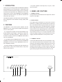
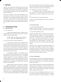
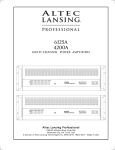
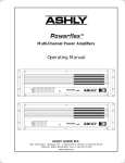
Model MM9340
Model MM9360
Power Amplifier
The lightning flash with arrowhead symbol, within an equalateral triangle, is intended to
alert the user to the presence of uninsulated "dangerous voltage" within the product's enclosure
that may be of sufficient magnitude to constitute
a risk of electric shock to persons.
The exclamation point within an
equalateral triangle is intended to alert the user
to the presence of important operating and maintenance instructions in the literature accompanying the device.
TO REDUCE THE RISK OF ELECTRIC SHOCK, DO NOT REMOVE COVER.
NO USER SERVICEABLE PARTS INSIDE. REFER SERVICING TO QUALIFIED
SERVICE PERSONNEL.
TO REDUCE THE RISK OF FIRE OR ELECTRICAL SHOCK, DO NOT EXPOSE
THIS APPLIANCE TO RAIN OR MOISTURE.
TO REDUCE THE RISK OF FIRE, REPLACE ONLY WITH SAME TYPE FUSE.
REFER REPLACEMENT TO QUALIFIED SERVICE PERSONNEL.
WARNING: THIS APPARATUS MUST BE EARTHED THROUGH THE
SUPPLIED POWER LINE CORD
2
SAFETY
INSTRUCTIONS
READ BEFORE OPERATING EQUIPMENT
This product was designed and manufactured to meet strict
quality and safety standards. There are, however, some installation and operation precautions which you should be particularly aware of.
1. Read Instructions - All the safety and operating instructions should be read before the appliance is operated.
2. Retain Instructions - The safety and operating instructions should be retained for future reference.
11. Power Sources - The appliance should be connected to
a power supply only of the type described in the operating instructions or as marked on the appliance.
12. Grounding or Polarization - The precautions that should
be taken so that the grounding or polarization means of
an appliance is not defeated.
3. Heed Warnings - All warnings on the appliance and in
the operating instructions should be adhered to.
13. Power-Cord Protection - Power-supply cords should be
routed so that they are not likely to be walked on or
pinched by items placed upon or against them, paying
particular attention to cords at plugs, convenience receptacles, and the point where they exit from the appliance.
4. Follow Instructions - All operating and use instructions
should be followed.
14. Cleaning - The appliance should be cleaned only as recommended by the manufacturer.
5. Water and Moisture - The appliance should not be used
near water - for example, near a bathtub, wash-bowl,
kitchen sink, laundry tub, in a wet basement, or near a
swimming pool, etc.
15. Nonuse Periods - The power cord of the appliance should
be unplugged from the outlet when left unused for a long
period of time.
6. Carts and Stands - The appliance should be used only
with a cart or stand that is recommended by the manufacturer.
7. An appliance and cart combination should be moved with
care. Quick stops, excessive force, and uneven surfaces
may cause the appliance and cart combination to over
turn.
8. Wall or Ceiling Mounting - The appliance should be
mounted to a wall or ceiling only as recommended by the
manufacturer.
16. Object and Liquid Entry - Care should be taken so that
objects do not fall and liquids are not spelled into the
enclosure through openings.
17. Damage Requiring Service - The appliance should be
serviced by qualified service personnel when:
A: The power-supply cord or the plug has been damaged; or
B: Objects have fallen, or liquid has spilled into the appliance; or
C: The appliance has been exposed to rain; or
9. Ventilation - The appliance should be situated so that its
location or position does not interfere with its proper ventilation. For example, the appliance should not be situated on a bed, sofa, rug, or similar surface that may block
the ventilation openings; or, placed in a built-in installation, such as a bookcase or cabinet that may impede the
flow of air through the ventilation openings.
10. Heat - The appliance should be situated away from heat
sources such as radiators, heat registers, stoves, or other
appliances (including amplifiers) that produce heat.
D: The appliance does not appear to operate normally
or exhibits a marked change in performance; or
E: The appliance has been dropped, or the enclosure
damaged.
18. Servicing - The user should not attempt to service the
appliance beyond that described in the operating instructions. All other servicing should be referred to qualified
service personnel.
3
1. INTRODUCTION
Thank you for purchasing the Marantz MM9360 or MM9340
power amplifier for your sound system. Please take a few
minutes to read this manual thoroughly, before you attempt
connections and operations.The illustrations used in this
manual refer to the six channel MM9360, but the MM9340
operates in the same manner, only with four channels and
more power per channel.
This Marantz appliance is a Multi channel power amplifier,
that is designed for home theatre and high quality audio
systems.
- The power amplifier will accept RCA, 1/4" jack, or XLR
input connectors.
3. NAMES AND FUNCTIONS
1. SIGNAL indicator
The signal present LEDs illuminate at an input level of about
13mVrms (-35.5dBu).
2. PEAK indicator
The clipping LEDs illuminate at an input level of about
870mVrms (+1.0dBu), with all channels driven by 1KHz into
2. FEATURES
The MM9360 is a six channel power amplifier, and the
MM9340 is a four channel power amplifier developed for
use in hi-fi AV systems.
- It is a high-power amplifier with efficient MOSFET highspeed switching output stages, controlled by internal microprocessor and DSP algorithms. Rated outputs per
channel are 150W / 8 ohms for the MM9360 and 275W / 8
ohms for the MM9340.
8Ω. This indicates that the signal processing circuitry has
determined output levels to be approaching the available
power supply rails and has begun to “soften” signal peaks.
Actual onset of “hard” clipping depends on audio program
and total load impedance and does not occur until the signal processing circuitry can no longer compensate, which
means that signal integrity can be maintained even if the
clipping indicators illuminate for short periods of time.
- It is provided with the MARANTZ RC-5 remote control
3. THERMAL indicator
capability so its power can be controlled from a MARANTZ
preamplifier or surround receiver (MARANTZ remote control compatible products).
The thermal LEDs illuminate when the temperature of any
- The power amplifier is equipped with LED indicators for
signal present, peak power, thermal status, and protect
mode for each channel.
one of the heat sink extrusions reaches 85 to 90°C. Both
channels of the affected amplifier module will shut off until
the measured temperature drops below about 70°C. The
amplifier should be able to maintain proper operation at
an ambient room temperature of 50°C (122°F) or less with
typical audio program and all channels driven into 4Ω.
6 C H P O W E R A M P L I F IE R M M 9 3 6 0
C
H
A
N
N
E
L
1
C
H
A
N
N
E
L
2
C
H
A
N
N
E
L
3
C
H
A
N
N
E
L
4
C
H
A
N
N
E
L
5
C
H
A
N
N
E
L
6
P
O
W
E
R
PO WER
O FF
ON
P R O T E CT
TH E R MA L
PEA K
S IG N A L
1
4
2
3
4
5
6
4. PROTECT indicator
5. POWER indicator
The protect LEDs illuminate when the fault monitoring microprocessor has determined that one of the following conditions exists:
The blue power LED comes on when the amplifier
is fully powered up.
6. POWER switch
- Power supply undervoltage
Press this switch to the ON position to turn the
power on, and to the OFF position to turn the power off.
When it is required to remote control the power mode of
- Power supply overvoltage
- Output overcurrent
the amplifier, be sure to leave this switch in the ON mode.
- Heat sink overtemperature
- Unacceptable DC output content
7. INPUT LEVEL control
- Unacceptable high frequency output content
- AC power interruption
Because the signal processing module processes two
channels simultaneously, a fault in one channel will result
in a protect condition for both channels processed by the
same module, ex. channels 1-2, 3-4, and 5-6 (MM9360
only). Thus there will never be a case where only one of
the amplifier channels is shown in protect mode. When a
pair of protect LED's are illuminated, internal relays have
removed the channel pair's speaker loads from the amplifier output and connected the speakers to ground. If the
fault is isolated to one module (channel pair), the other
level.
8. STEREO/BRIDGE MONO switch
This switch selects between normal stereo channel mode for two adjacent channels, or bridge mono mode,
where two channels are supplied the same signal with the
second channel's phase inverted 180°. The speaker is
then connected across the (+) red output connections of
the two channels, resulting in twice the power to the speaker
that either channel could deliver by itself. Since in Bridge
Mode both connections have voltage present, never connect or touch either speaker wire to ground.
channels will remain unaffected.
7
This control sets the amplifier's output level by
adjusting its input level. When two adjacent amplifier channels are switched into bridge mono mode, only the odd
number channel level controls (1, 3, 5) determine signal
8
CH1
(1-2 MONO)
4
3
CH 2
5
4
6
7
8
2
1
9
PUSH
CH3
7
9
0
1
9
10
0
STEREO
BRIDG E MO NO
PUSH
5
CH5
7
1
1
10
0
7
8
1
10
9
10
0
STEREO
BRIDG E MO NO
P U SH
6
2
9
0
5
3
8
2
9
4
7
3
8
2
CH 6
(1-2 MONO)
4 5 6
6
3
8
2
10
4
7
3
8
1
CH 4
(1-2 MONO)
4 5 6
6
2
10
0
5
3
STEREO
BRIDG E MO NO
P U SH
P U SH
CAUTION
MODEL NO. MM9360
P U SH
115V
RISKOFELECTRICSHOCK
DONOTOPEN
50/60Hz 1400W
B RID G E M O DE
STEREO MODE
150W / C H A N - 8 O HM S
250W / C H A N - 4 O HM S
C H 1 (MONO)
CH 2
C H 3 (MONO)
CH 4
C H 5 (MONO)
IN
OU T
B RID G E
CH1
CH2
CH3
CH4
CH5
CH6
+
IN
-
B RID G E
-
+
+
-
OU T
REP LA C E O N LY W IT H
SAM E TYP E FU SE
R E F ER T O O W N E R 'S M A N U A L
FO R PRO PER FU S E RA T ING
AC
9
O UTPU TS
B RID G E
CH 6
D C TR IG G E R
R C -5 R E M O T E
CO NT RO L
T AK E OU T P UT F R OM
T W O RE D P OS T S
DO N OT C ONN E CT E IT HE R
OU T PU T W IR E TO GR OU ND
B RID G E M O DE
50 0W B RID GE - 8 OH M S
10 11
12 13
14
(+ )
(+ )
(+ )
(+ )
(+ )
(+ )
CH 1
CH 2
CH 3
CH 4
CH 5
CH 6
(-)
(-)
(-)
(-)
(-)
(-)
M A N U F A C T U R E D IN T H E U S A B Y A S H L Y A U D IO IN C O R P O R A T E D
15
5
9. INPUT XLR and ¼" PHONE jacks
(Gnd)
The amplifier uses 1/4" phone jacks and female XLR jacks
for balanced input signals, recommended for longer input
Tip (+)
cables and to minimize hum and noise.
Sleeve (Gnd)
(+)
Ring (-)
RCA Plug
Stereo Phone Plug
used for balanced
Balanced Inputs
It is recommended that balanced input connections be used
whenever possible to take full advantage of the amplifier's
common mode rejection properties, and to reduce groundloop problems. The (+) signal is on pin 2 of the XLR, and
the tip of the phone jack. The (-) signal is on pin 3 of the
Tip (+)
Sleeve (Gnd)
M ono Phone Plug
used for unbalanced
XLR, and the ring of the phone jack.
Unbalanced Inputs
If an unbalanced XLR input connection is used, pin 3 should
be connected to input ground (pin 1). If the ¼" input jack
is used unbalanced, the use of a mono (tip-sleeve) plug
will automatically tie the (-) connection to input ground.
Note: Never float the (+) or (-) input connection when using an unbalanced source.
XLR pins are
numbered
on the
connector
insert.
2 = (+)
3 = (-)
1 = (gnd)
XLR M ale
10. RC-5 IN/OUT jack
If your system uses a Marantz remote control compatible component with preamplifier outputs, such as an
A/V preamplifier or surround receiver, these jacks allow
you to turn the power of the amplifier to ON or OFF/Standby
through remote control from the preamplifier or receiver.
Before using these jacks, check the owner's manual of the
Marantz component to see if it is remote control compatible.
11. AC INLET
13. AC FUSE drawer
This is where the AC line fuse is located. In the event of
fuse failure, replace only with MDA 12 250V.
14. INPUT RCA jacks
Connect the preamplifier output to this jack. Since these
connections use unbalanced signals, they are more
succeptable to picking up radiated noise such as magnetic
field from a large power transformer, electric motors,
flourescent lights, computer and video cables, etc. For
Connect AC cord (Supplied) and plug into a grounded AC
power outlet.
best noise performance, keep these cables short and avoid
passing them near any potential noise source.
12. DC TRIGGER jacks
15. SPEAKER SYSTEM terminals
Two 3.5mm jacks are used for remote switching between
ON status and OFF/Standby status. An external 12 volt
Dual binding posts provide connections for the speaker out-
DC power supply wired in series with a switch is required
for the DC trigger input. Wire the switched DC to the tip of
a 3.5mm miniature phone plug for the DC trigger input,
and wire the power supply ground to the sleeve. Be sure
to use a latching (push-push) type switch rather than a momentary switch. Assuming the amplifier's main AC power
switch is on, an input voltage transition from 0 to 12 volts
turns on the amplifier (if already in OFF/Standby mode),
and after a one second delay provides 12 volts to the DC
Trigger Out jack for remote control of other amplifiers. A
DC trigger input voltage transition from 12 volts to 0 volts
returns the amplifier into Off/Standby mode.
6
puts. In addition to using the banana-type plug, the binding posts have a slotted entry-way for wire-crimped spade
terminals. In BRIDGE MONO mode, the channel 1, 3, or 5
red binding post is the (+) in-phase speaker output terminal and the channel 2, 4, or 6 red binding post becomes
the (-) out-of-phase speaker terminal.
CAUTION! NEVER CONNECT THE TWO RED BINDING
POSTS TOGETHER OR CONNECT EITHER RED BINDING POST TO A BLACK BINDING POST!
CH1
(1-2 MONO)
4
3
CH 2
5
4
6
8
2
1
7
9
0
8
2
1
10
4
CH5
7
10
3
8
1
9
10
0
CH 6
(1-2 MONO)
4 5 6
6
2
9
0
5
3
7
STEREO
BRIDG E MO NO
PUSH
PUSH
CH 4
3
8
1
10
CH3
(1-2 MONO)
4 5 6
6
2
9
0
5
3
7
4
8
2
1
7
8
1
10
9
10
0
STEREO
BRIDG E MO NO
P U SH
6
2
9
0
5
3
7
STEREO
BRIDG E MO NO
P U SH
P U SH
CAUTION
MODEL NO. MM9360
P U SH
115V
RISKOFELECTRICSHOCK
DONOTOPEN
50/60Hz 1400W
B R ID G E M O D E
S T E R E O M O DE
150W / C H A N - 8 OH M S
250W / C H A N - 4 OH M S
C H 1 (MONO)
CH 2
C H 3 (MONO)
CH 4
C H 5 (MONO)
CH 6
D C TR IG G ER
R C -5 R E M O T E
C O NT R OL
IN
OU T
CH2
CH3
CH4
CH5
CH6
+
IN
O UT PU TS
B R ID G E
B R ID G E
CH1
T AK E OU T PU T F RO M
T W O RE D PO ST S
D O N OT C ON NE C T EIT HE R
OU T PU T W IR E T O GR OU ND
B R ID G E M O D E
500W B RID GE - 8 OH M S
-
+
B R ID G E
-
+
-
OU T
R E PLA C E O N L Y W IT H
SA M E TY PE FUSE
R E FER TO O W N ER 'S M A N U A L
FO R PRO P ER FU SE RA T ING
AC
(+ )
(+ )
(+ )
(+ )
(+ )
CH 1
CH 2
CH 3
CH 4
CH 5
CH 6
(+ )
(-)
(-)
(-)
(-)
(-)
(-)
M A N U F A C T U R E D IN T H E U S A B Y A S H L Y A U D IO IN C O R P O R A T E D
To
Power
Outlet
Front
Surround
Center
-L-
-L-
Center
Out
Marantz
Remote
Control
L
R
Front
L
R
Surround
Cen
Sub
Center
Typical Surround Preamplifier Outputs
Typical Wiring Diagram
-
+
-
-
+
-
+
Sub
-R-
-R-
-
+
+
-
+
4. SPEAKER CONNECTIONS
6. CARE AND MAINTENANCE
This equipment, being a high audio output power ampli-
This section describes the car and maintenance tasks that
fier, has a hazardous energy at its speaker terminal. Please
be sure to make an appropriate speaker connection according to the following procedure:
must be performed to optimize the operation of your
marantz equipment.
- Confirm that the power switch of the equipment is at "OFF"
position. If it is at "ON", turn it to "OFF" position to connect a speaker cable.
- Use a speaker cable with the flame retardant rating of
type SPT12 or more.
- For bare wire connections, strip the insulation off no more
than 3/8" at the speaker terminal connection of speaker
cable, and twist the exposed wire. For banana-type plugs
or spade terminals, follow the instructions of the connector manufacturer.
- Connect speakers in correct polarity, according to the
indication for the polarity of speaker terminals. For bare
wire or spade terminal connections, first loosen the speaker
CLEANING OF EQUIPMENT EXTERNAL SURFACES
The exterior finish of your unit will last indefinitely with
proper care and cleaning. Never use scouring pads, steel
wool, scouring powders or harsh chemical agents (e.g. lye
solution), alcohol, thinners, benzine insecticide or other
volatile substances as these will mar the finish of the equipment.
Likewise, never use cloths containing chemical substances.
If the equipment gets dirty, wipe the external surface with
a soft, lint free cloth.
If the equipment becomes heavily soiled:
- Dilute some washing up liquid in water, in a ratio of one
part detergent to six parts water.
terminal by turning in a counter-clockwise direction, insert
the bare wire or spade terminal, then re-tighten by turning
the terminal clockwise.
- Dip a soft, lint free cloth in the solution and wring the
cloth out until it is damp.
- Prevent any stress from being applied to the speaker cable
- Dry the equipment by wiping it with a dry cloth.
- Wipe the equipment with the damp cloth.
connected to the speaker terminal.
- Don't touch the speaker terminals during operation.
7
7. REPAIRS
Only the most competent and qualified technicians should
be allowed to service your unit. Marantz and its factory
trained warranty station personnel have the knowledge and
special equipment needed for repair and calibration of this
precision instrument.
fier power for that channel is evenly divided among speakers, so 100 watts driving two parallel speakers of equal
impedance provides 50 watts to each speaker, etc.
3.) Thermal LED and Protect LEDs stay on:
An amplifier module is in thermal protect mode
and needs to cool. The fan will continue to run while in
In the event of difficulty, call the toll-free telephone number listed on the face of the warranty to obtain the name
and address of the Marantz Authorized Service Center
nearest you. Please include the model, serial number of
thermal protect, and other modules will continue to function.
your unit together with a copy of your purchase receipt and
a full description of what you feel is abnormal in its behavior.
There is no input signal applied or input level controls are
4.) Power LED lit but no Signal LED activity
turned down.
8.2 Distorted Sound
8. TROUBLESHOOTING
8.1 No Audio Output
1.) Power LED not lit:
Unit may be in stand-by mode if connected to compatible Marantz product's stand-by output control. Line fuse
is blown or power outlet is dead.
IF LINE FUSE HAS FAILED, REPLACE ONLY
WITH SAME TYPE AND RATING FUSE.
2.) Power LED is lit but Protect LEDs stay on:
Amp module is in protect mode. Speakers have
been internally disconnected from amplifier output and connected to ground until the protect fault is corrected. Output overcurrent, overvoltage and undervoltage faults will
reset in about eight seconds once the fault condition is
removed, while excessive DC offset or high frequency faults
take about 30 seconds to reset.
Low Speaker Impedance: The amplifier may go
into self-protect at high output levels if the actual speaker
load impedance is much less than 4 ohms. To calculate
speaker impedance for a given combination of directcoupled speakers, use Ohm's law as applied to series and/
or parallel resistor networks, where each speaker (for this
purpose) can be thought of as a single resistor, using DC
resistance measurements.
Simply stated, speakers connected in series will
add together their impedance. Conversely, two speakers
connected in parallel will result in half the impedance, three
parallel speakers a third the impedance, four speakers a
fourth, and so on, assuming the speaker impedances are
all the same. Don't use mismatched impedances in parallel. When using paralleled speakers, the available ampli-
1.) Clip LED is flashing regularly
Amplifier is being overdriven. Turn down the input level
control, or reduce the output level from the signal source.
2.) Clip LED is not flashing at all
Amplifier input signal may be exceeding input headroom,
which is greater than +12dBu, or 3.4V rms (measured using continuous 1kHz sine wave). Incoming signal level
higher than +12.8 dBu will cause distortion in the amplifier. Turning down the input level controls will not eliminate distortion if the input headroom is exceeded. Turn
down the output level of the device driving the amplifier
instead.
Additionally, an input signal may already be distorted before it gets to the amplifier. Check to see if a piece of
equipment in the signal chain before the amp is clipping.
For best performance, the amplifier should be operated
with input levels fully CW. Also check for damaged speaker
drivers that could cause distorted sound.
8.3 Hum or Buzz Noise
Be sure that the power cord’s 3-prong plug is connected to
a properly earth-grounded outlet. Lifting the grounding third
prong may not improve hum or buzz and can create a potential shock hazard.
Hum is usually caused by ground currents flowing between
different pieces of equipment. Ground currents can be
minimized by using a single point AC ground for the sound
system, and by using balanced connections with quality
cable throughout the audio path.
Buzz, as well as certain audible high frequency tones, can
be caused by environmental emissions such as lighting
dimmers, neon lights, or computer equipment. Use bal-
8
anced connections, and try moving the amplifier, wiring,
lighting, or other equipment to different locations to isolate
the source of the noise.
9. SPECIFICATIONS
*Power Output
(Maximum Average Power, 0.1% THD, 1KHz)
Connections
Input: XLR - 1/4” (Pin 2: Hot, Tip: Hot), RCA
Output: 5-Way Binding Post
Rated Per Channel, Two Channels Driven
4 ohm:
8 ohm:
Mono Bridged
(1 Channel)
8 ohm:
MM9360
250W RMS
150W RMS
MM9340
400W RMS
275W RMS
500W RMS
800W RMS
Dimensions: 17 5/16” W x 5 3/4” H x 13 1/8” D
Rated Per Channel, All Channels Driven
4 ohm:
8 ohm:
Mono Bridged
8 ohm:
Cooling: Forced Air, Thermal Sensitive Variable Speed Fan,
Front Inlet/Rear Outlet
MM9360
250W RMS†
150W RMS
MM9340
400W RMS†
275W RMS
500W RMS
800Watts RMS
Input Impedance: 20K ohm balanced, 10K ohm unbalanced,
3.65K ohm RCA
**THD ( Full Power 1KHz @ 8 ohms): < 0.06%
**THD (20Hz-20KHz @ 8 ohms): < 0.2%
**IMD
(SMPTE 60Hz/7KHz 4:1)
@ 8 ohms: <0.2% (throughout power range)
(IHF) @ 8 ohms: <0.1% (throughout power range)
Construction: 14 Gauge All-Steel Chassis, Aluminum Front
Panel
Weight:
Shipping
Net
MM9360
51lbs.
45lbs.
MM9340
50lbs.
44lbs.
Specification conditions: 120VAC 60Hz, 25°C
* Continuous power limited by power line capacity
**Non-conventional amplifiers require bandwidth limiting for
all distortion and noise measurements.
† Signal peaks in audio programming may trigger protection
circuitry at low line voltages. Specifications are subject to
change or improvement without notice.
**Hum and Noise: -100dB from full output (A-weighted)
Full Power Input Sensitivity:
MM9360
1.08V RMS (2.9dBu)
MM9340
1.47V RMS (5.6dBu)
Frequency Response:
8 ohm: ±0.5dB 20Hz-20kHz
4 ohm: ±1.5dB 20Hz-20kHz
Voltage Gain: 32X (30.1dB)
Crosstalk: < -80dB (20Hz - 1KHz)
Signal Present Signal Sensitivity: 13mV RMS (-35.5dBu)
Power Requirement:
110-125VAC 50/60Hz
Typical Idle Current
MM9360
120V: 0.81A
MM9340
120V: 0.9A
Current with Typical Audio Program Material (4 ohm load all Channels)
MM9360
MM9340
120V: 6.5A
120V: 7.0A
9
10
11
Marantz America, Inc.
1100 Maplewood Drive
Itasca, Illinois 60143
phone: 630.741.0300 fax: 630.741.0301
Printed in USA
MM9X1-09/03