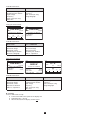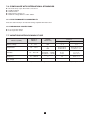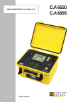
1
MEGOHMMETER ENGLISH User’s manual C.A 6549 Thank you for purchasing a C.A. 6549 megohmmeter. To obtain the best service from your instrument: read this user manual carefully, comply with the precautions for use. WARNING, risk of DANGER! The operator must refer to this user’s manual whenever this danger symbol appears. Equipment protected by double insulation. WARNING! Risk of electric shock. The voltage of the parts identified by this symbol may be ≥ 120 Vdc. For safety reasons, this symbol is displayed when such a voltage is generated. Earth. The CE marking indicates conformity with European directives, in particular LVD and EMC. The rubbish bin with a line through it indicates that, in the European Union, the product must undergo selective disposal in compliance with Directive WEEE 2002/96/EC. This equipment must not be treated as household waste. Definition of measurement categories: Measurement category IV corresponds to measurements taken at the source of low-voltage installations. Example: power feeders, counters and protection devices. Measurement category III corresponds to measurements on building installations. Example: distribution panel, circuit-breakers, machines or fixed industrial devices. Measurement category II corresponds to measurements taken on circuits directly connected to low-voltage installations. Example: power supply to electro-domestic devices and portable tools. PRECAUTIONS FOR USE This device is compliant with safety standard IEC 61010-2-030 and the leads are compliant with IEC 61010-031, for voltages up to 1000 V with respect to earth in category III. Failure to observe the safety instructions may result in electric shock, fire, explosion, and destruction of the instrument and of the installations. The operator and/or the responsible authority must carefully read and clearly understand the various precautions to be taken in use. Sound knowledge and a keen awareness of electrical hazards are essential when using this instrument. If you use this instrument other than as specified, the protection it provides may be compromised, thereby endangering you. Do not use the instrument on networks of which the voltage or category exceeds those mentioned. Do not use the instrument if it seems to be damaged, incomplete, or poorly closed. Before each use, check the condition of the insulation on the leads, housing, and accessories. Any item of which the insulation is deteriorated (even partially) must be set aside for repair or scrapping. Use personal protection equipment systematically. Use only the accessories delivered with the instrument. Respect the value and type of the fuse to avoid damaging the instrument and cancelling the warranty. Set the switch to OFF when the instrument is not in use. The battery must be charged before metrological tests. All troubleshooting and metrological checks must be performed by competent and accredited personnel. 2 CONTENTS 1. PRESENTATION........................................................................................................................................................................ 4 1.1. The megohmmeter.......................................................................................................................................................... 4 1.2. The accessories.............................................................................................................................................................. 4 2. DESCRIPTION........................................................................................................................................................................... 5 2.1. Housing........................................................................................................................................................................... 5 2.2. Keys................................................................................................................................................................................. 6 2.2. Display............................................................................................................................................................................. 6 3. MEASUREMENT FUNCTIONS................................................................................................................................................. 8 3.1. AC / DC voltage............................................................................................................................................................... 8 3.2. Insulation measurement.................................................................................................................................................. 8 3.3. Capacitance measurement............................................................................................................................................. 9 3.4. Residual current measurement....................................................................................................................................... 9 4. SPECIAL FUNCTIONS............................................................................................................................................................ 10 4.1. MODE / PRINT key........................................................................................................................................................ 10 4.2. DISPLAY / GRAPH key.................................................................................................................................................. 13 4.3. / T° Key...................................................................................................................................................................... 19 4.4. / SMOOTH Key......................................................................................................................................................... 20 4.5. SET-UP function (instrument configuration).................................................................................................................. 20 4.6. List of coded errors....................................................................................................................................................... 24 5. PROCEDURE.......................................................................................................................................................................... 25 5.1. Course of measurements.............................................................................................................................................. 25 5.2. Step function mode (Adj. Step)..................................................................................................................................... 26 6. MEMORY / RS 232.................................................................................................................................................................. 28 6.1. RS 232 characteristics.................................................................................................................................................. 28 6.2. Storing / recalling measurement results (MEM/MR KEY).............................................................................................. 28 6.3. Printing measured values (PRINT key).......................................................................................................................... 29 7. SPECIFICATIONS.................................................................................................................................................................... 34 7.1. Reference conditions..................................................................................................................................................... 34 7.2. Characteristics per function.......................................................................................................................................... 34 7.3. Power supply................................................................................................................................................................. 37 7.4. Environmental conditions.............................................................................................................................................. 37 7.5. Construction specifications........................................................................................................................................... 37 7.6. Compliance with international standards...................................................................................................................... 38 7.7. Variations within domain of use..................................................................................................................................... 38 8. MAINTENANCE............................................................................................................................................................... 39 8.1. Servicing........................................................................................................................................................................ 39 8.2. Metrological check........................................................................................................................................................ 39 8.3. Repair............................................................................................................................................................................ 39 9. WARRANTY............................................................................................................................................................................. 40 10. TO ORDER............................................................................................................................................................................. 41 10.1. Accessories................................................................................................................................................................. 41 10.2. Replacement parts...................................................................................................................................................... 41 3 1. PRESENTATION 1.1. THE MEGOHMMETER The C.A 6549 megohmmeter is a portable unit, fitted into a rugged construction site casing with cover, operating on battery or line power. Its main functions are: automatic detection and measurement of voltage, frequency, input current, quantitative and qualitative insulation measurement: measurement at 500, 1000, 2500, 5000 Vdc or other test voltage between 40 and 5100 Vdc (“adjustable voltage”), measurement in voltage step mode (the applied voltage increases in steps), automatic calculation of DAR/PI and DD (dielectric discharge index) quality ratios, automatic calculation of measurement result referred to a reference temperature. automatic capacitance measurement, automatic measurement of residual current. This megohmmeter helps to ensure the safety of electrical installations and equipment. Its operation is controlled by microprocessor for the acquisition, processing, measurement display, storage and printing of results. It offers a wide range of advantages such as: digital filtering of insulation measurements, automatic voltage measurement, threshold programming, to trigger alarms using audible beeps, the timer for measurement duration checks, protection of the device by fuse, with detection of defective fuses, operator safety by means of automatic discharge of the test voltage on the equipment tested, automatic power save mode of the device to save battery power, indication of battery charge condition, large graphic display with backlight capability, memory (128 kB), real time clock and serial interface, PC control of the device (using PC software, optional), printing in RS 232 or Centronics mode. 1.2. THE ACCESSORIES 1.2.1. MEASURING CABLES The megohmmeter is delivered with 4 measuring cables as standard: 2 3m safety cables (red & black with rear pick up), with an HV plug for connection to the instrument and an HV alligator clip for connection to the item tested 2 blue cables (3 m and 0.3 m with rear pick up) to measure high insulation values (see § 5.1). Optionally, you can order the same cables in lengths of 8 m and 15 m, and also simplified cables (the alligator clip is replaced by a 4 mm banana jack to which standard alligator clips or contact pins can be connected). 1.2.2. PC SOFTWARE (OPTIONAL) This PC software is used to: download data stored in the instrument, print customised test protocols in accordance with user needs, create ExcelTM spreadsheets, configure and control the unit via the RS 232, The minimum recommended configuration is a PC with a 486DX100 processor. 1.2.3. SERIAL PRINTER (OPTIONAL) This compact printer can be used to print measurement results, directly in the field. 1.2.4. SERIAL-PARALLEL ADAPTER (OPTIONAL) The optional RS232/Centronics adapter converts the serial interface (RS232) into a parallel printer interface (Centronics), making it possible to print all measurements directly on A4-format office printers, without using a personal computer. 4 2. DESCRIPTION 2.1. HOUSING ➆ ➇ ➁ ➂ ➅ ➀ ➃ ➄ ➀ ➁ ➂ 3 4mm-dia. safety terminals identified as “+”, “G”, and “-”. Access to the fuse that protects terminal “G”. 8-way rotary switch: OFF 500V - 2TΩ 1000V - 4TΩ 2500V - 10TΩ 5000V - 10TΩ Adjust. 50V...5000V Adjust. STEP SET-UP ➃ ➄ ➅ ➆ ➇ switches instrument power off. insulation measurement at 500 V up to 2 TΩ. insulation measurement at 1000 V up to 4 TΩ. insulation measurement at 2500 V up to 10 TΩ. insulation measurement at 5000 V up to 10 TΩ. insulation measurement with adjustable test voltage (from 40 V to 5100 V: 10 V steps from 40 to 1000 V and 100 V steps from 1000 to 5100 V). insulation measurement with voltage step function (the test voltage varies in steps). adjustment of instrument configuration. 1 yellow START / STOP key: beginning / end of measurement 8 elastomer keys each having a main function and a secondary function. 1 backlit graphic screen. 1 socket for connection to line power (direct operation on line power and/or battery charging). 1 RS 232 serial INTERFACE male connector (9 pins) for connection to a PC or printer. 5 2.2. KEYS 8 keys each having a main function and a secondary function: 2nd Select the secondary function (indicated in yellow italics below each key). MODE PRINT Primary function: select the desired type of measurement, before an insulation measurement, or select the current range, during a measurement. Secondary function: enter the PRINT menu to print measurement results. DISPLAY GRAPH Primary function: browse through the various screens accessible before, during and after the measurement. Secondary function: display insulation resistance versus duration after a time-limited measurement. u Primary function: select a parameter one step to the right of the current cursor position (from the end of the line, the cursor jumps to the beginning of the line). Secondary function: activate/deactivate display backlight. T° Primary function: deselect a selection or move the cursor one parameter to the left. Secondary function: enter the TEMPERATURE menu to refer the measurement to a specified temperature. p Primary function: move the cursor up or increment the selected parameter (flashing or indicated by the cursor). If the key is kept pressed, the rate of change of the parameters is increased. Secondary function: activate / deactivate the alarms programmed in the SET-UP menu , or move the cursor one page up in a long menu.. ALARM q SMOOTH MEM MR Primary function: move the cursor down or decrement the selected parameter (flashing or indicated by the cursor). If the key is kept pressed, the rate of change of the parameters is increased. Secondary function: enable / disable smoothing of the insulation resistance indication, or move the cursor one page down in a long menu. Primary function: store measured values. Secondary function: recall stored data. 2.3. DISPLAY 2.3.1. GRAPHIC DISPLAY UNIT The display unit is a graphic display unit with a resolution of 320 x 240 pixels. It has a built-in backlighting that can be activated or deactivated using the key. The various screens that are accessible are presented and explained throughout this manual. We explain below, however, the various symbols that may appear on the screen. 2.3.2. SYMBOLS REMOTE Indicates that the instrument is controlled remotely via the interface. In this mode, all of the keys and the rotary switch are inactive, except for shutdown of the instrument (OFF position). COM Indicates that the instrument is sending data to the printer via the interface. 2nd Indicates that the secondary function of a key will be used. Indicates that the “programmed time test” mode was selected before the measurement was started. DAR Indicates that the “automatic calculation of Dielectric Absorption Ratio” mode was selected before the measurement was started. PI Indicates that the “automatic calculation of Polarization Index” mode was selected before the measurement was started. DD Indicates that the “automatic calculation of Dielectric Discharge Index” mode was selected before the measurement was started. SMOOTH Indicates that smoothing of the insulation resistance indication is activated. ALARM Indicates that the alarm is enabled. An audible alarm will be emitted if the value measured is below the limit value defined in the SET-UP menu. Indicates the battery charge condition (see § 8.1.1). 6 Voltage generated dangerous, U > 120Vdc. External voltage present, U > 25 VRMS 7 3. MEASUREMENT FUNCTIONS 3.1. AC / DC VOLTAGE Turning the switch to an insulation position (position other than OFF or SET-UP) sets the instrument to automatic AC / DC voltage measurement. The voltage between the input terminals is measured at all times and indicated as RMS value on the display unit: Input Voltage. Switching between AC and DC mode is automatic. When switch is turned, the frequency and the residual DC current between the terminals of the instrument are also measured. (The residual current is measured in order to evaluate its impact on the insulation measurement to come). FIXED VOLTAGE 2500 V Input voltage Frequency Input current Date: 24.06.2008 230 V AC 50.0 Hz 24.6 nA Time: 15:31 The insulation measurements cannot be started if there is an excessively high external voltage on the terminals, in which case the symbol is displayed next to the measured external voltage (see § 3.2). 3.2. INSULATION MEASUREMENT When the switch is turned to an insulation position, one of the following displays appears: Case 1 You select an insulation measurement with a fixed / standard test voltage, in manual mode. FIXED VOLTAGE 2500 V Positions: 500V - 2TΩ 1000V - 4TΩ 2500V - 10TΩ 5000V - 10TΩ Input voltage Frequency Input current Date: 24.06.2008 Case 2 You select an insulation measurement with a test voltage other than those proposed as standard. Position: Adjust. 50V...5000V You can choose from the 3 “adjusted” voltages predefined in SET-UP using the and keys, or define another voltage by selecting it with the key and adjusting it with the and keys. 8 230 V AC 50.0 Hz 24.6 nA Time: 15:31 ADJUSTABLE VOLATGE 1 2300 V Input voltage Frequency Input current Date: 24.06.2008 20 V AC 50.0 Hz 24.6 nA Time: 15:31 Case 3 You select an insulation measurement with a test voltage that varies in steps: this is the “step function” mode. STEP FUNCTION 1 Min: 2300 V Position: Adjust. Step You can choose among the three step functions ( and keys) you defined earlier in SET-UP. Max: 3900 V Test Run Time 08:38:30 Input voltage Frequency Input current Date: 24.06.2008 Pressing the START/STOP key immediately triggers the measurement. An audible beep is emitted every 10 seconds to indicate that a measurement is in progress. 1 V AC 50.0 Hz 24.6 nA Time: 15:31 Important remark: These insulation measurements cannot be started if there is an excessively high external voltage on the terminals. If, when the START key is pressed, the external voltage on the terminals of the instrument is greater than the value U peak defined below, the insulation measurement is not triggered and an audible alarm is emitted; the instrument then returns to automatic voltage measurement. U peak ≥ 2 x dlSt x Un where - Upeak: external voltage, peak or DC, on the terminals of the instrument. - dlSt: coefficient that can be adjusted in SET-UP - 3% (default value), 10% or 20%. - Un: test voltage selected for the insulation measurement. Similarly, if during the insulation measurements, an external voltage greater than the value U peak defined below is detected, the measurement is stopped and the symbol appears next to the value of the external voltage measured. U peak ≥ (dlSt + 1.1) x Un, where - Upeak: external voltage, peak or DC, on the terminals of the instrument. - dlSt: coefficient that can be adjusted in SET-UP - 3% (default value), 10% or 20%. - Un: test voltage selected for the insulation measurement. Note: Adjust the dISt factor to optimize the measurement build-up time. If there is no disturbance voltage, dISt can be set to its minimum value to obtain the shortest possible measurement build-up time. If there is a large disturbance voltage, dISt can be increased so that the measurement can be started and will not be interrupted. Pressing the START/STOP key again stops the measurement. If a “programmed time test” mode (Timed Run or Timed Run + DD) was selected as measurement mode, the measurement is stopped (without action on the START/STOP button) at the end of this time. Similarly, if the DAR or PI mode is selected as measurement mode, the measurement is stopped after the time needed to calculate them. Note: When measuring resistances smaller than the resistance range indicated for the selected test voltage, the test voltage is automatically reduced. So 10 kW can be measured as the minimum resistance regardless of the selected test voltage.. 3.3. CAPACITANCE MEASUREMENT The capacitance measurement is performed automatically during the insulation measurement, and is displayed after the measurement stops and the circuit has been discharged. 3.4. RESIDUAL CURRENT MEASUREMENT The residual current circulating in the installation is measured automatically upon connection to the installation, then before and after the insulation measurement. 9 4. SPECIAL FUNCTIONS 4.1. MODE / PRINT KEY 4.1.1. PRIMARY FUNCTION BEFORE THE MEASUREMENT The primary function of the MODE key is very important: it is used before the measurement to define the course of the measurement. This key is inactive in the “Adjust. Step” and SET-UP positions. Pressing the MODE key gives access to the list of possible measurement modes. Select the mode using the and/or keys. To validate the mode selected, press the MODE key again. The various measurement modes are as follows: MANUAL STOP: This is the conventional quantitative insulation measurement mode. The measurement is started by pressing START / STOP and stopped by pressing START / STOP again. The user determines the duration, which is indicated by the measurement duration chronometer. MANUAL STOP + DD: The measurement is started by pressing START/STOP and stopped by pressing START/STOP again. One minute after the end of the measurement, the instrument calculates and display the DD term. The time remaining during this minute is displayed. TIMED RUN: (Timed run test) This mode is used to perform a measurement for a duration defined in advance, with a predetermined number of measurement samples: the measurement is started by pressing START / STOP and stops automatically after the time programmed by the user. This duration (Duration) and the time interval between samples (Sample) can be modified using the , , and keys when the Timed Run mode is selected. When the measurement is started, the chronometer counts down the time remaining. When this time (Remaining Time) is zero, the measurement is stopped. MODE Total Run Time --Manual Stop Manual Stop + DD Duration Sample (h:m) (m:s) Timed Run 02:30 00:10 Timed Run + DD DAR (s/s) 30/60 PI (m/m) 1.0/10 MODE Total Run Time --Manual Stop Manual Stop + DD Duration Sample (h:m) (m:s) Timed Run 02:30 00:10 Timed Run + DD DAR (s/s) 30/60 PI (m/m) 1.0/10 MODE Total Run Time 02:30:00 Manual Stop Manual Stop + DD Duration Sample (h:m) (m:s) Timed Run 02:30 00:10 Timed Run + DD DAR (s/s) 30/60 PI (m/m) 1.0/10 During the execution of a timed run test, the intermediate samples are automatically stored: they are used to plot insulation resistance vs. time. This curve can be displayed after the measurement by pressing the GRAPH key, as long as no new measurement has been started. The samples are automatically stored with the final value of the resistance, if it is stored. During the measurement, if the position of the rotary switch is changed, or the STOP key is pressed, the measurement is stopped. 10 TIMED RUN + DD: This mode is identical to the previous one except that 1 minute after the end of the measurement the instrument calculates and displays the DD term. The measurement duration is therefore: duration of timed run + 1 minute. The insulation resistance vs. time curve can be displayed after the measurement by pressing GRAPH, as long as no new measurement has been started. MODE Total Run Time 02:30:00 Manual Stop Manual Stop + DD Duration Sample (h:m) (m:s) Timed Run 02:30 00:10 Timed Run + DD DAR (s/s) 30/60 PI (m/m) 1.0/10 DAR: The measurement is started by pressing START / STOP and stops automatically when the DAR ratio has been calculated, i.e. after 1 minute, the time for measuring the second insulation resistance value needed for the calculation (the sample time can be modified with the , , and keys). MODE Total Run Time 00:01:00 Manual Stop Manual Stop + DD Duration Sample (h:m) (m:s) Timed Run 02:30 00:10 Timed Run + DD DAR (s/s) 30/60 PI (m/m) 1.0/10 PI: The measurement is started by pressing START / STOP and stops automatically when the PI ratio has been calculated, i.e. after 10 minutes, the time for measuring the second insulation resistance value needed for the calculation (the sample times can be modified with the , , and keys). MODE Total Run Time 00:10:00 Manual Stop Manual Stop + DD Duration Sample (h:m) (m:s) Timed Run 02:30 00:10 Timed Run + DD DAR (s/s) 30/60 PI (m/m) 1.0/10 Remark: in this mode, the DAR ratio will also be calculated automatically if the times needed to calculate it are less than the second time needed to calculate the PI ratio. Important remarks: What is the DD (Dielectric Discharge index)? In the case of multilayer insulation, if one of the layers is defective but the resistance of all the others is high, neither the quantitative insulation measurement nor the calculation of the PI and DAR quality ratios will reveal the problem. This makes it judicious to perform a dielectric discharge test, from which the DD term can be calculated. This test measures the dielectric absorption of heterogeneous or multilayer insulation and disregards parallel-surface leakage currents. It involves applying a test voltage for long enough to electrically “charge” the insulation to be measured (typically, a voltage of 500 V is applied for 30 minutes). At the end of the measurement, the instrument causes a rapid discharge, during which the capacitance of the insulation is measured; 1 minute later, the residual current circulating in the insulation is measured. The DD term is then calculated as follows: DD = current measured after 1 minute (mA) / [test voltage (V) x measured capacitance (F)] The insulation quality rating as a function of the value found is as follows: Value of DD Quality of insulation 7 < DD Very poor 4 < DD < 7 Poor 2 < DD < 4 Borderline DD < 2 Good Note: The dielectric discharge test is especially well suited to insulation measurements on rotating machines, and, in general, to insulation measurements on heterogeneous or multilayer insulations containing organic materials. 11 What are the DAR (Dielectric Absorption Ratio) and the PI (Polarization Index)? It is useful to calculate insulation quality ratios in addition to the quantitative insulation resistance value, because they can be used to eliminate the influence of certain parameters likely to invalidate the “absolute” insulation measurement. The most important of these parameters are: temperature and relative humidity, with which insulation resistance varies according to a quasi-exponential law. the disturbance currents (capacitive charging current, dielectric absorption current) created by the application of the test voltage. Even though they gradually vanish, they perturb the measurement at the start, for a length of time that depends on whether the insulation is in good condition or degraded. These ratios complete the “absolute” insulation value, and reliably reflect whether the insulation is in good or poor condition. In addition, changes in these ratios over time can be observed and used for predictive maintenance, e.g. to monitor the ageing of the insulation of a population of rotating machines. The DAR and PI ratios are calculated as follows: PI = R 10 min / R 1 min (2 values to be noted during a 10-min measurement.) DAR = R 1 min / R 30 sec(2 values to be noted during a 1-min measurement.) Remark: Note that the times of 1 & 10 min for the calculation of PI and 30 & 60 seconds for the calculation of DAR are those currently used and programmed as defaults in the instrument. They can however be modified in SET-UP to adapt to a possible change in a standard or to the needs of a specific application. A capacitance in parallel to the insulation resistance extends the settling times of the measurements. This can affect or even inhibit the measurement of DAR or PI (depending on the time set for recording the first resistance value). The following table shows typical values for the capacitance in parallel to the insulation resistance at which a successful DAR or PI measurement is still possible (at the default time for recording the first resistance value). 100 kW 1 MW 10 MW 100 MW 1 GW 10 GW 100 GW 50 V 40 µF 40 µF 20 µF 10 µF 1 µF 0 µF 0 µF 100 V 40 µF 40 µF 20 µF 10 µF 1 µF 0 µF 0 µF 500 V 20 µF 20 µF 10 µF 5 µF 2 µF 1 µF 1 µF 1000 V 5 µF 5 µF 5 µF 2 µF 2 µF 1 µF 1 µF 2500 V 2 µF 2 µF 2 µF 1 µF 0.5 µF 0 µF 0 µF 5000 V 1 µF 1 µF 1 µF 0,5 µF 0.5 µF 0 µF 0 µF Interpretation of the results: DAR PI Condition of insulation <1 <2 Poor or even dangerous < 1.6 <4 Good > 1.6 >4 Excellent < 1.25 4.1.2. PRIMARY FUNCTION DURING THE MEASUREMENT During the measurement, the first function of the MODE key is to select the Range of the current: automatic (default) or fixed. Display range < 10 MW > 10 MW GW TW Number 3 2 1 1 Press the MODE key, then the key to select the Range, then the or key to modify it. The choice of Range of current is validated by pressing the MODE key again. The choice remains active until the switch is turned. In the Adj. Volt. position, the MODE key can be used to modify the voltage value during the measurement. 12 4.1.3. SECONDARY FUNCTION The PRINT secondary function is described in § 6.3 (Printing of measured values). 4.2. DISPLAY / GRAPH KEY 4.2.1. PRIMARY FUNCTION DISPLAY This key is used to browse through the various accessible screens containing all information available before, during or after the measurement. The screens vary depending on the mode selected before the measurement is started. MANUAL STOP mode Before the measurement 0.1 V FIXED VOLTAGE 500 V Input voltage Frequency Input current Date: 24.06.2008 0.0 Hz 0.1 V AC 0.0 Hz 24.6 pA Time: 15:32 24.6 pA AC V 0 100 250 500 750 1000 Available information: First screen Press on DISPLAY Selected test voltage Input voltage Frequency Input current (DC only) Date, time Input voltage Frequency Input current (DC only) Voltage bargraph During the measurement 234.5 MΩ 234.5 MΩ 507 V 224.6 pA Elapsed Time 00:00:43 kΩ 1 10 100 MΩ 1 10 100 GΩ 1 10 100 TΩ 10 507 V 224.6 pA Elapsed Time 00:00:43 DAR (30s/60s) --PI (1.0m/10m) --Capacitance --- Available information: First screen Press on DISPLAY Insulation resistance Measured voltage Measured current Elapsed test duration Resistance bargraph Insulation resistance Measured voltage Measured current Elapsed test duration DAR, PI, capacitance 13 After the measurement 234.5 MΩ 0.1 V FIXED VOLTAGE 507 V 224.6 pA Elapsed Time 01:02:43 DAR (30s/60s) 2.64 PI (1.0m/10m) 1.05 Capacitance 320 nF 500 V Input voltage Frequency Input current Date: 24.06.2008 0.0 Hz 0.1 V AC 0.0 Hz 24.6 pA Time: 15:31 24.6 pA AC V 0 100 250 500 750 Available information: First screen Press on DISPLAY 2nd press on DISPLAY Insulation resistance Measured voltage Measured current Elapsed test duration DAR, PI, capacitance Selected test voltage Input voltage Frequency Input current (DC only) Date, time Input voltage Frequency Input current (DC only) Voltage bargraph MANUAL STOP + DD mode Before the measurement 0.1 V FIXED VOLTAGE 500 V Input voltage Frequency Input current Date: 24.06.2008 0.0 Hz 0.1 V AC 0.0 Hz 24.6 pA Time: 15:32 24.6 pA AC V 0 100 250 500 750 1000 Available information: First screen Press on DISPLAY Selected test voltage Input voltage Frequency Input current (DC only) Date, time Input voltage Frequency Input current (DC only) Voltage bargraph During the measurement 234.5 MΩ 234.5 MΩ 507 V 224.6 pA Elapsed Time 00:00:43 kΩ 1 10 100 MΩ 1 10 100 GΩ 1 10 100 TΩ 10 507 V 224.6 pA Elapsed Time 00:00:43 DAR (30s/60s) --PI (1.0m/10m) --Capacitance --DD current --- pA DD --- Available information: First screen Press on DISPLAY Insulation resistance Measured voltage Measured current Elapsed test duration Resistance bargraph Insulation resistance Measured voltage Measured current Elapsed test duration DAR, PI, capacitance Current (for the calculation of DD) DD 14 1000 After the measurement 234.5 MΩ 0.1 V FIXED VOLTAGE 507 V 224.6 pA Elapsed Time 00:22:43 DAR (30s/60s) 2.24 PI (1.0m/10m) 1.56 Capacitance 220 nF DD current 11.55 pA DD 2.55 500 V Input voltage Frequency Input current Date: 24.06.2008 0.0 Hz 0.1 V AC 0.0 Hz 24.6 pA Time: 15:32 24.6 pA AC V 0 100 250 500 750 Available information: First screen Press on DISPLAY 2nd press on DISPLAY Insulation resistance Measured voltage Measured current Elapsed test duration DAR, PI, capacitance Current (for the calculation of DD) DD Selected test voltage Input voltage Frequency Input current (DC only) Date, time Input voltage Frequency Input current (DC only) Voltage bargraph TIMED RUN mode Before the measurement 0.1 V ADJUSTABLE VOLTAGE 2 2300 V 0.0 Hz Input voltage Frequency Input current Date: 24.06.2008 0.1 V AC 0.0 Hz 24.6 pA Time: 15:32 24.6 pA AC Test Run Time 00:10:00 V 0 100 250 500 750 1000 Available information: First screen Press on DISPLAY Selected test voltage Programmed test duration Input voltage Frequency Input current (DC only) Date, time Input voltage Frequency Input current (DC only) Voltage bargraph During the measurement 234.5 MΩ 234.5 MΩ 2307 V 24.6 pA Remaining Time 00:09:43 kΩ 1 10 100 MΩ 1 10 100 GΩ 1 10 100 TΩ 10 2307 V 24.6 pA Remaining Time 00:09:43 DAR (30s/60s) --PI (1.0m/10m) --Capacitance --- 15 1000 Available information: First screen Press on DISPLAY Insulation resistance Measured voltage Measured current Remaining test duration Resistance bargraph Insulation resistance Measured voltage Measured current Remaining test duration DAR, PI, capacitance After the measurement 234.5 MΩ 2307 V 24.6 pA Elapsed Time 00:10:00 DAR (30s/60s) 2.64 PI (1.0m/10m) 1.05 Capacitance 320 nF 0.1 V ADJUSTABLE VOLTAGE 2 2300 V 0.0 Hz Input voltage Frequency Input current Date: 24.06.2008 0.1 V AC 0.0 Hz 24.6 pA Time: 15:32 24.6 pA AC Test Run Time 00:10:00 V 0 100 250 500 750 Available information: First screen Press on DISPLAY 2nd press on DISPLAY Insulation resistance Measured voltage Measured current Test duration DAR, PI, capacitance Selected test voltage Programmed test duration Input voltage Frequency Input current (DC only) Date, time Input voltage Frequency Input current (DC only) Voltage bargraph TIMED RUN + DD mode Before the measurement DD DD 0.1 V ADJUSTABLE VOLTAGE 2 2300 V 0.0 Hz Input voltage Frequency Input current Date: 24.06.2008 0.1 V AC 0.0 Hz 24.6 pA Time: 15:32 24.6 pA AC Test Run Time 00:10:00 V 0 100 250 500 750 1000 Available information: First screen Press on DISPLAY Selected test voltage Programmed test duration Input voltage Frequency Input current (DC only) Date, time Input voltage Frequency Input current (DC only) Voltage bargraph 16 1000 During the measurement DD DD 234.5 MΩ 234.5 MΩ 2307 V 24.6 pA Remaining Time 00:09:43 kΩ 1 10 100 MΩ 1 10 100 GΩ 1 10 100 TΩ 10 2307 V 24.6 pA Remaining Time 00:09:43 DAR (30s/60s) --PI (1.0m/10m) --Capacitance --DD current --- pA DD --- Available information: First screen Press on DISPLAY Insulation resistance Measured voltage Measured current Remaining test duration Resistance bargraph Insulation resistance Measured voltage Measured current Remaining test duration DAR, PI, capacitance Current (for the calculation of DD) DD After the measurement DD DD 234.5 MΩ 2307 V 224.6 pA Elapsed Time 00:10:00 DAR (30s/60s) 2.24 PI (1.0m/10m) 1.56 Capacitance 220 nF DD current 11.55 pA DD 2.55 DD 0.1 V ADJUSTABLE VOLTAGE 2 2300 V 0.0 Hz Input voltage Frequency Input current Date: 24.06.2008 0.1 V AC 0.0 Hz 24.6 pA Time: 15:32 24.6 pA AC Test Run Time 00:10:00 V 0 100 250 500 750 Available information: First screen Press on DISPLAY 2nd press on DISPLAY Insulation resistance Measured voltage Measured current Test duration DAR, PI, capacitance Current (for the calculation of DD) DD Selected test voltage Programmed test duration Input voltage Frequency Input current (DC only) Date, time Input voltage Frequency Input current (DC only) Voltage bargraph DAR mode Before the measurement DAR DAR 0.1 V FIXED VOLTAGE 500 V 0.0 Hz AC Test Run Time 00:01:00 Input voltage Frequency Input current Date: 24.06.2008 0.1 V AC 0.0 Hz 24.6 pA Time: 15:32 24.6 pA V 0 100 250 500 750 1000 17 1000 Available information: First screen Press on DISPLAY Selected test voltage Programmed test duration Input voltage Frequency Input current (DC only) Date, time Input voltage Frequency Input current (DC only) Voltage bargraph During the measurement DAR DAR 234.5 MΩ 5007 V 24.6 pA Remaining Time 00:00:43 kΩ 1 10 100 MΩ 1 10 100 GΩ 1 10 100 TΩ 10 234.5 MΩ 5007 V 24.6 pA Remaining Time 00:09:43 DAR (30s/60s) --PI (1.0m/10m) --Capacitance --- Available information: First screen Press on DISPLAY Insulation resistance Measured voltage Measured current Remaining test duration Resistance bargraph Insulation resistance Measured voltage Measured current Remaining test duration DAR, PI, capacitance After the measurement DAR DAR DAR 234.5 MΩ 5007 V 224.6 pA Elapsed Time 00:01:00 DAR (30s/60s) 2.24 PI (1.0m/10m) --Capacitance 220 nF 0.1 V FIXED VOLTAGE 5000 V 0.0 Hz Input voltage Frequency Input current Date: 24.06.2008 0.1 V AC 0.0 Hz 24.6 pA Time: 15:32 24.6 pA AC Test Run Time 00:01:00 V 0 100 250 500 750 Available information: First screen Press on DISPLAY 2nd press on DISPLAY Insulation resistance Measured voltage Measured current Elapsed test duration DAR, PI, capacitance Selected test voltage Programmed test duration Input voltage Frequency Input current (DC only) Date, time Input voltage Frequency Input current (DC only) Voltage bargraph PI mode Same as DAR mode except: PI instead of DAR at the top left of the display unit Remaining Time = 10 min After the measurement: display of DAR and PI. 18 1000 4.2.2. GRAPH SECONDARY FUNCTION This function is used to display the insulation resistance versus measurement time curve after a time-limited measurement (Timed Run or Timed Run + DD). This curve is plotted from the samples recorded during the measurement. The , , and keys can be used to move along the curve to display the exact values of each sample. GRAPH 5078 V MΩ 3000 2500 2000 1500 1000 500 0 2428.5 MΩ 00:02:30 0:30 1:00 1:30 2:30 3:00 4.3. / T° KEY The T° secondary function can be used in two ways. One is to assign a Probe Temperature to an insulation resistance measurement, the other to refer the resistance to a temperature different from the measurement temperature. This makes it possible to observe the insulation resistance over time and judge its evolution under comparable temperature conditions. This is because insulation resistance varies with temperature according to a quasi-exponential law. As part of a maintenance program covering a population of motors, for example, it is important to perform periodic measurements under similar temperature conditions. Otherwise, the results obtained must be corrected to refer them to a fixed reference temperature. This function can do this. Attention: The T° function is not available in the Adjustable Step position. If the result of the insulation resistance measurement is out of range (“<” or “>”) no temperature corrected resistance can be calculated. Procedure: You have just made a measurement and have not yet stored it. Make sure that the result is not out of range, then enter the T° mode by pressing 2nd then T°. TEMPERATURE Probe Temperature Resistance Correction Rc Reference Temperature ∆T for R/2 R measured Rc at 40°C 23°C On 40°C 10°C 1.002 MΩ 309 kΩ Enter the Probe Temperature at which you made the measurement (by default, the instrument proposes the value set in SET-UP). If you want to know the resistance of the probe at another temperature, set “Resistance Correction” to “On” to perform the calculation. The calculation is performed immediately and the result is displayed: Rc. This indicates what the measurement result would have been at the reference temperature. Use the , , and keys to modify the temperatures. To assign this calculation (or only the Probe Temperature) to the measurement result, press 2nd + T° again (OK is then displayed). Remarks: During the procedure, pressing the DISPLAY key or turning the switch cancels the modifications. If the coefficient ∆T used for the calculation is not known, the instrument can calculate it in advance, using at least 3 stored measurements made at different temperatures (see § 4.5.3) Detail concerning the calculation performed: The insulation resistance varies with the measurement temperature. This dependence can be approximated by an exponential function: Rc = KT * RT where Rc: insulation resistance at reference temperature. RT: insulation resistance measured at T°C (Probe Temperature). KT: coefficient at T°C defined as follows: KT = (1/2) ^ ((Rc Reference Temperature - T) / ∆T) with T: temperature at the time of the measurement (Probe Temperature) ∆T: temperature difference at which the insulation resistance is halved. Rc Reference Temperature: temperature for which the temperature corrected resistance (Rc) is calculated. 19 4.4. / SMOOTH KEY The SMOOTH secondary function activates / deactivates an insulation measurement digital filter. It affects only the display (which is smoothed), not the measurements. This function is useful if the insulation values displayed are very unstable. The filter is calculated as follows: RSMOOTH = RSMOOTH + (R – RSMOOTH) / N Since N is set to 20, the time constant of this filter is approximately 20 seconds. 4.5. SET-UP FUNCTION (INSTRUMENT CONFIGURATION) This function, located on the rotary switch, can be used to change the configuration of the instrument by accessing directly the parameters to be modified. Turning the rotary switch to SET-UP gives you access to the menu of all modifiable parameters. Select the parameter to be modified and its value using the , , and keys. 4.5.1. SET-UP MENU SET-UP Instr.Nr. 700016 SW Version 1.8 Display Contrast 80 Alarm Settings Adjust Voltage 1 50 V Adjust Voltage 2 100 V Adjust Voltage 3 250 V Timed Run (h:m) 0:10 Sample Time (m:s) 0:10 DAR (s/s) 30/60 SET-UP Instr.Nr. 700016 SW Version 1.8 PI (m/m) 1.0/10 Set Step Function 1 Set Step Function 2 Set Step Function 3 Temperature Unit Celsius Defaut Probe Temperature 23°C Rc Reference Temperature 40°C ∆T for R/2 10°C SET-UP Instr.Nr. 700016 SW Version 1.8 Calculate ∆T from Memory Maximum Output Voltage 5100V Set Defaut Parameter Clear Memory V Disturbance / V Output 3% Buzzer On Power Down On BaudRate 9600 / RS 232 SET-UP Instr.Nr. 700016 SW Version 1.8 Clear Memory V Disturbance / V Output 3% Buzzer On Power Down On BaudRate 9600 / RS 232 Units Europe Date (d.m.y) 27.04.2009 Time (h:m) 10:21 Description of each instrument configuration parameter: Display Contrast: modification of display unit contrast. Default value Range 80 0 … 255 Attention: the display unit is no longer legible above 130. Alarm Settings: programming of measurement threshold values below which an audible alarm is triggered. 500 V 1000 V 2500 V 5000 V Adj. Voltage 1 Adj. Voltage 2 Adj. Voltage 3 Default value Range < 500 kW < 1.0 MW < 2.5 MW < 5 MW < 50 kW < 100 kW < 250 kW 30 kW … 2 TW 100 kW … 4 TW 300 kW … 10 TW 300 kW … 10 TW 10 kW … 10 TW 10 kW … 10 TW 10 kW … 10 TW Note: to return to the SET-UP menu, press the DISPLAY key. Adjustable Voltage 1, 2, 3: adjustable voltage: 3 different values can be predefined. Adjustable Voltage 1 Adjustable Voltage 2 Adjustable Voltage 3 Default value Range 50 V 100 V 250 V 40 … 5100 V in steps of 10 V from 40 to 1000 V in steps of 100 V from 1000 to 5100 V. 20 Timed Run (h:m): duration of test in "Timed run" mode. Default value Range 00: 10 (h:m) 00: 01 … 49: 59 (h:m) Sample Time (m:s): time interval between samples recorded in Timed Run mode for plotting R(t). Default value Range 00: 10 (m:s) 00: 05 … 59: 59 (m:s) The limit depends on the duration set for the Timed Run. DAR (s/s): 1ST and 2ND times for the DAR calculation. Default value Range 30 / 60 (s/s) 10 … 90 / 15 … 180 (s/s) 5-second steps PI (m/m): 1ST et 2ND times for the PI calculation. Default value Range 01 / 10 (m/m) 0.5 … 30 (0.5-, then 1-min steps) /1 … 90 (0.5-, then 1-, then 5-min steps) Set Step Function 1, 2, 3: for each predefined step function, definition of the various voltages, of the duration of each step, and of the interval for the recording of samples. To skip a step, set the duration or the voltage to “---”. Default value Voltage Range Duration (h:m) Step Function 1 Step 1 Step 2 Step 3 Step 4 Step 5 50 V 100 V 150 V 200 V 250 V sample time 00: 01 00: 01 00: 01 00: 01 00: 01 00: 10 (m:s) Step 1 Step 2 Step 3 Step 4 Step 5 100 V 300 V 500 V 700 V 900 V sample time 00: 01 00: 01 00: 01 00: 01 00: 01 00: 10 (m:s) Step 1 Step 2 Step 3 Step 4 Step 5 1000 V 2000 V 3000 V 4000 V 5000 V sample time 00: 01 00: 01 00: 01 00: 01 00: 01 00: 10 (m:s) Step Function 2 Step Function 3 Voltage 40 … 5100 V in 10-V then 100‑V steps 40 … 5100 V in 10-V then 100‑V steps 40 … 5100 V in 10-V then 100‑V steps Duration (h:m) 00: 09 … 09: 59 00: 09 … 09: 59 00: 09 … 09: 59 00: 09 … 09: 59 00: 09 … 09: 59 see note (00: 05…59: 59) The limit depends on the duration set for the Timed Run. 00: 09 … 09: 59 00: 09 … 09: 59 00: 09 … 09: 59 00: 09 … 09: 59 00: 09 … 09: 59 see note (00: 05…59: 59) The limit depends on the duration set for the Timed Run. 00: 09 … 09: 59 00: 09 … 09: 59 00: 09 … 09: 59 00: 09 … 09: 59 00: 09 … 09: 59 see note (00: 05…59: 59) The limit depends on the duration set for the Timed Run. Note: the minimum sample time depends on the total duration of the test (Total Run Time). It is equal to Sample Time (seconds) = (h+1)*5 where h= hours of the Total Run Time. 21 Temperature Unit: selection of temperature unit. Default value Range °C °C or °F Default Probe Temperature: measurement temperature. Default value Range 23 °C -15°C … +75°C Rc Reference Temperature: reference temperature to which the measurement result must be referred. Default value Range 40 °C -15°C … +75°C DT for R/2: estimated ∆T to obtain an insulation resistance / 2. Default value Range 10 °C -15°C … +75°C Calculate ∆T from Memory: used to calculate ∆T from 3 stored measurements made using the same probe at different temperatures (see § 4.5.3). Maximum Output Voltage: imposes maximum/locking of test voltage. Default value Range 5100 V 40 … 5100 V Set Default Parameter: default configuration: reinitializes the instrument with the default values of all parameters. Clear Memory: can be used to partially or completely erase stored data (see § 4.5.2). V Disturbance / V Output = dlSt factor (see § 3.2 - Important remark). Default value Range 3% 3, 10 or 20 % Buzzer: enabling / disabling of buzzer (keys, measurements, alarms). Default value Range On On or Off Power Down: automatic power save mode of the instrument after 1 min if no key is activated. Default value Range Off On or Off Baud Rate: RS 232 communication format and rate (see § 6.1) Default value Range 9600 / RS 232 300 … 9600 / RS 232 or --- / Parallel Units: defines in which style the Date is displayed. Default value Range Europe Europe or USA 22 Date (d.m.y): current date or setting of date. Europe dd.mm.yyyy USA mm.dd.yyyy Time (h:m): current time or setting of time. 4.5.2. MEMORY ERASURE In SET-UP, select Clear memory. To erase the content of one or more specific OBJ: TEST numbers Select Select Data Sets to Clear by pressing . Then each stored measurement to be erased using , , or . Validate by pressing DISPLAY. The operation is confirmed or cancelled by pressing . SET-UP Clear Memory : Select Data Sets to Clear Clear All SET-UP Clear Memory : Obj. Test Date Time 47 99 15.12.2008 07:04 13 59 07.12.2008 18:39 13 58 24.11.2008 15:04 02 03 31.08.2008 15:47 02 02 29.06.2008 16:56 02 01 30.04.2008 08:43 01 02 16.03.2008 09:07 SET-UP ! WARNING ! Fct. 625V 3800V 50V 2150V 975V 5000V All selected data sets will be cleared ! O.K. CANCEL To erase the entire memory Select Clear All by pressing . The operation is confirmed or cancelled by pressing . SET-UP Clear Memory : Select Data Sets to Clear Clear All SET-UP ! WARNING ! All data sets will be cleared ! O.K. CANCEL 4.5.3. CALCULATION OF ∆T FROM STORED DATA The coefficient ∆T is used to calculate the insulation resistance at a temperature other than the measurement temperature (see. § 4.3). It is the temperature difference at which the insulation resistance concerned is reduced to half its value.. This coefficient is variable: it depends on the type of insulation. When it is not known, the instrument can calculate it from three or more stored measurements. Attention, these 3 measurements must have been made by the same device (identical insulation resistance) but at 3 different temperatures, and the temperatures must have been recorded (function 2nd + T°) at the same time as the measurements, without applying the correction (Resistance Correction OFF). Procedure: In SET-UP, select Calculate ∆T from Memory and press . The display unit proposes all values recorded with a temperature. 23 SET-UP Instr.Nr. 700016 SW Version 1.8 Calculate ∆T from Memory Maximum Output Voltage 5100V Set Defaut Parameter Clear Memory V Disturbance / V Output 3% Buzzer On Power Down On BaudRate 9600 / RS 232 Select at least 3 measurements using the , , or . ∆T is calculated and recorded automatically once 3 stored measurements have been selected, and updated as more measurements are selected. The larger the number of measurements, the more accurate the calculation of ∆T. SET-UP 23.7°C ∆T Calculation fot R/2 Obj. Test Res. Volt. Temp. 47 99 228.5 MΩ 5078V 23°C 13 59 208.5 MΩ 5078V 30°C 13 58 178.5 MΩ 5078V 37°C 02 03 328.5 MΩ 5078V 23°C 02 02 328.5 MΩ 5078V 23°C 02 01 328.5 MΩ 5078V 23°C 01 02 328.5 MΩ 5078V 23°C 4.5.4. MAXIMUM OUTPUT VOLTAGE In the SET-UP menu, select Maximum Output Voltage. Adjust the maximum output voltage using the key, then the or keys. This function prohibits the use of certain test voltages for the insulation measurement. The instrument can then be used by less experienced persons for specific applications (telephony, aeronautics, etc.) where it is important not to exceed some maximum test voltage. SET-UP Instr.Nr. 700016 SW Version 1.8 Calculate ∆T from Memory Maximum Output Voltage 5100V Set Defaut Parameter Clear Memory V Disturbance / V Output 3% Buzzer On Power Down On BaudRate 9600 / RS 232 For example, if the maximum output voltage is set to 750 V, the measurement will be made at 500 V in switch position 500 V, and at not more than 750 V in all other positions. 4.6. LIST OF CODED ERRORS If an anomaly is detected when the instrument is started up or in operation, the display indicates an error code. The format of this error code is a 1- or 2-digit number. This number identifies the anomaly and the action to be taken. Error 10: There is an error in the user memory for storing measurement data. Use Clear Memory then Clear All in SET-UP to initialise the memory. Attention, all stored data will be lost. Error 21: There is an error in the user settings. Use Set Default Parameter in SET-UP to initialise the settings. Error 25: There is an error in the printer file format. A new format must be loaded into the instrument. If the error message «Memory not initialized!» is displayed, proceed as described in Error 10. All other errors require returning of the instrument for repair. 24 5. PROCEDURE 5.1. COURSE OF MEASUREMENTS Start up the instrument by setting the switch to the position corresponding to the measurement to be made. The instrument can measure insulation values from 10 kΩ to 10 TΩ, depending on the test voltage selected-from 40 to 5100 Vdc. The screen displays: the battery symbol and battery charge condition, the test voltage selected, the voltage, frequency and residual current on the input terminals, the date and time. FIXED VOLTAGE 2500 V Connect the cables of the + and - terminals to the measurement points.. Input voltage Frequency Input current Date: 24.06.2008 230 V AC 50.0 Hz 24.6 nA Time: 15:31 Connection diagram for measurement of low insulation values (example of a motor) + M - To measure high insulation values (> 1 GΩ), we recommend using guard terminal “G” to avoid leakage and capacitive effects or eliminate the influence of surface leakage currents. The guard terminal is connected to a surface where leakage currents may flow through dust and humidity, e.g. the insulation surface of a cable or transformer, between two measurement points. Connection diagram for measurement of high insulation values a) Example of a motor (reduction of capacitive effects) - M 25 G + b) Example of a cable (reduction of surface leakage effects) Braid External insulator Insulator Guard G + - Cable Core Unless the step function mode is selected (Adj. Step), select the measurement mode to be used (Manual Stop, Manual Stop + DD, Timed Run, Timed Run + DD, DAR or PI) by pressing the MODE key (see § 4.1) A press on START/STOP triggers the measurement. If the voltage present is greater than the maximum allowed value, the measurement will be disabled (see § 3.2). The DISPLAY key can be used to consult all information available during the measurement. This information depends on the measurement mode selected (see § 4.2). If the insulation values displayed are very unstable, a digital filter can be activated by pressing SMOOTH to smooth them (see § 4.4). The alarm mode can be activated by pressing ALARM. An audible beep will sound if the measurement result is below the value defined in SET-UP (see § 4.5). Pressing START/STOP again stops the measurement. The last result remains displayed until the next measurement is made, the MODE is changed or the switch is turned. When the insulation measurements stop, the circuit tested is automatically discharged via a resistor in the instrument. The DISPLAY key can be used to consult all information available after the measurement. This information depends on the measurement mode selected (see § 4.2). If the measurement was in a “programmed-time test” mode (DAR, PI, Timed Run or Timed Run + DD), pressing GRAPH displays the insulation measurement versus time curve (see § 4.2). Pressing T° enters the TEMPERATURE menu (see § 4.3). 5.2. STEP FUNCTION MODE (ADJ. STEP) This test is based on the principle that an ideal insulation produces the same resistance whatever test voltage is applied. Any negative variation of this resistance therefore means that the insulation is defective: the resistance of defective insulation decreases as the test voltage increases. This phenomenon is barely observed with “low” test voltages. In consequence, at least 2500 V should be applied. The usual test condition is a voltage increasing in steps: 5 1-min steps. Assessment of the result: a deviation of the resistance = f(test voltage) curve that exceeds 500 ppm/V generally indicates the presence of mould or other deterioration. a larger deviation or a sudden drop indicates the presence of localized physical damage (arcing, perforation of the insulation, etc.). 26 Procedure: In the SET-UP menu, select Set Step Function 1, 2 or 3. Example: here, step function n°3. SET-UP Instr.Nr. 700016 SW Version 1.8 PI (m/m) 1.0/10 Set Step Function 1 Set Step Function 2 Set Step Function 3 Temperature Unit Celsius Defaut Probe Temperature 23°C Rc Reference Temperature 40°C ∆T for R/2 10°C Define the step function and the sample interval is automatically adjusted.. Once the step function is defined, set the switch to Adj. Step and select Step Function n°3 using the or key. Start the measurement by pressing START/STOP SET-UP Step Function 3 : Voltage Step Duration (h:m) 1 1000V 00:01 2 2000V 00:02 3 3000V 00:03 4 4000V 00:04 5 5000V 00:05 Total Run Time (h:m) 00:15 Sample Time (m:s) 00:30 STEP FUNCTION 3 Min: 1000 V Max: 5000 V Test Run Time 00:15:00 Input voltage Frequency Input current Date: 24.06.2008 0.1 V DC 0.0 Hz 24.6 nA Time: 15:31 During the measurement, the following screens can be accessed by pressing the DISPLAY key. 234.5 MΩ 234.5 MΩ 999 V 224.6 pA Remainning Time 00:14:30 kΩ 1 10 100 MΩ 1 10 100 GΩ 1 10 100 TΩ 10 999 V 224.6 pA Remainning Time 00:14:15 --- MΩ ∆R 300 V ∆V --∆R/(R*∆V) (ppm/V) --Capacitance At the end of the measurement, the following results are indicated: the difference ∆R in insulation resistance between the resistance at the highest test voltage and the resistance at the lowest test voltage, the difference ∆V between the highest and lowest test voltage, the slope of the curve in ppm/V, the capacitance. Pressing the GRAPH key displays the resistance versus time curve. Using the and keys, it is possible to move along the curves and view the exact values of each sample. 27 6. MEMORY / RS 232 6.1. RS 232 CHARACTERISTICS The baud rate can be set to 300, 600, 1200, 2400, 4800, 9600, or Parallel for printing on parallel printers via the optional serial / parallel adapter. This adjustment is performed in the SET-UP menu (see § 4.5) Data format: 8 data bits, 1 stop bit, no parity, Xon / Xoff protocol Connection to the serial printer: DB9F ➔ DB9M 2 ➔ 2 5➔5 3 ➔ 3 6➔6 4 ➔ 4 8➔8 Connection to a PC or to a parallel printer: DB9F ➔ DB9F 2 ➔ 3 5➔5 3 ➔ 2 6➔4 4 ➔ 6 8➔7 Note: check that there is no connection between pins 6 and 8 of the RS232 port of the instrument. 6.2. STORING / RECALLING MEASUREMENT RESULTS (MEM/MR KEY) 6.2.1. MEM PRIMARY FUNCTION (STORAGE) This function is used to store the results in the instrument’s RAM. The results can be stored at addresses identified by an object number (OBJ) and a test number (TEST). An object represents a “box” in which 99 tests can be stored. An object can thus represent a machine or an installation on which a number of measurements are performed. When the MEM key is activated, the following screen is displayed. The flashing cursor identifies the next free Obj: Test location, here: 13: 59. It is always possible to modify Obj.: Test to another free address using the , , or keys. If an empty Obj. is selected, Test is set to 01. Press the MEM key again to store the current measurement results at the selected free location. Store Obj. Test 13 59 13 58 02 03 02 02 02 01 01 02 01 02 MEMORY Date 28.04.2009 28.04.2009 14.04.2009 14.04.2009 14.04.2009 01.04.2009 01.04.2009 Time 09:04 09:00 15:07 15:04 14:56 10:43 10:38 Fct. 2550V 1020V 510V 1020V 5000V 510V MEMORY To store at an already occupied address (to overwrite a previously stored result) move the cursor in the list of stored results shown below the current measurement result and press the or MEM key. A warning screen is displayed and prompts the user to confirm or cancel erasure of the content of the address. To validate, use the key. ! WARNING ! Old data set wil be overwritten ! O.K. CANCEL Pressing the MEM key again stores the current measurement results at the selected address. All information about a measurement will be stored at a single location in memory: date, time, test mode and voltage, insulation resistance, capacitance, residual current, and, possibly, DAR, PI, DD, resistance referred to the reference temperature, etc. Note: To exit from the MEM menu without storing the results press the DISPLAY key. Memory space available The bargraph indicates memory usage: black - already occupied memory space white - free memory space grey - amount of memory space the current measurement will need if stored (not always visible, because size depends on measurement) 28 The number of measurements that can be stored depends on the kind of measurements: “Programmed-time tests” need a different amount of memory space depending on test duration and sample interval for recording intermediate results. A test duration of one hour and a sampling interval of 5 seconds takes the most amount of memory space; a maximum of 16 of such measurements can be stored. “Ordinary” measurements need much less memory space. Up to 1184 of such measurements can be stored. 6.2.2. MR SECONDARY FUNCTION The MR function is used to recall any data from memory, whatever the active position of the rotary switch, except for the OFF and SET-UP positions. When the MR key is activated, the following screen is displayed. The flashing cursor identifies the highest occupied Obj. Test number, here 13: 59. Use the and keys to move the cursor to the desired Obj. Test number. Press the key to recall the measurement and show the results. Use the DISPLAY key to browse through the data. Recall Obj. Test 13 59 13 58 13 57 02 03 02 02 02 01 01 02 01 02 MEMORY Date Time 28.04.2009 09:04 28.04.2009 09:00 28.04.2009 08:50 14.04.2009 15:07 14.04.2009 15:04 14.04.2009 14:56 01.04.2009 10:43 01.04.2009 10:38 Fct. 2550V 1020V 5000V 510V 1020V 5000V 510V Depending on the measurement mode a graph may be available by pressing the GRAPH key. Except for Adjustable Step measurements the TEMPERATURE menu is available by pressing the T° key. To enter the PRINT menu to print of the measurement, press the PRINT key. To exit from the MR function, press MR again or turn the switch. 6.3. PRINTING MEASURED VALUES (PRINT KEY) Pressing the PRINT key gives access to the menu below: Print result: Present measurement result: following a measurement or after access to the MR mode. PRINT Print result Print memory Baud rate / Port 9600 / RS 232 Print memory Printing of stored measurements. Baud rate / Port Baud rate selected in the SET-UP menu (see § 4.5). The COM symbol in the top right corner of the display indicates data transmission to the printer. 6.3.1. PRESENT MEASUREMENT RESULT: PRINT RESULT When this printing mode is selected, the following are printed, in order: general information concerning the measurement, the measurement result, if the T° function was activated, the measurement result referred to the reference temperature, for a Timed Run test, the list of recorded samples. To stop printing, turn the rotary switch. Depending on the measurement performed, the following forms are obtained. All measurements except step function measurements: CHAUVIN ARNOUX C.A 6549 Instrument number: 700 016 Company:.............................................. Address:................................................ .............................................................. Tel.:........................................................ Fax:........................................................ Email:..................................................... Description:........................................... 29 OBJECT: 01 TEST: 01 INSULATION RESISTANCE TEST Date:30.04.2009 Starting time: 14h55 Duration:00:15:30 Temperature:23°C Relative humidity: ....% Test voltage: 1000 V Insulation resistance: 385 GOhm -------------------------Rc - calculated resistance118.5 GOhm at reference temperature 40°C with ∆T for R/2 10°C -------------------------DAR (1’/30”) 1.234 PI (10’/1’) 2.345 DD -.-Capacitance 110 nF -------------------------Elapsed time Utest Resistance -------------------------00:00:10 1020 V 35.94 GOhm 00:00:30 1020 V 42.0 GOhm 00:00:50 1020 V 43.5 GOhm …etc (printed only in MR mode) (after timed run test) Date of next test: ../../..... Remarks:............................................... .............................................................. Operator:............................................... Signature:.............................................. Step function measurement: CHAUVIN ARNOUX C.A 6549 Instrument number: 700 016 Company:.............................................. Address:................................................ .............................................................. Tel.:........................................................ Fax:........................................................ Email:..................................................... Description:........................................... OBJECT: 01 TEST: 01 (printed only in MR mode) STEP FUNCTION TEST Date:30.04.2009 Starting time: 14h55 Duration:00:15:30 Temperature:23°C Relative humidity: ....% -------------------------Step DurationTrue def. Resistance N° h:m voltage -------------------------1 00:10 1020 V 2.627 GOhm 2 00:10 2043V 2.411 GOhm 3 00:10 3060 V 2.347 GOhm 4 00:10 3755 V 2.182 GOhm 5 00:10 3237 V 2.023 GOhm DR DV 604 GOhm 4000 V 30 DR / (R*DV) (ppm/v) -57 ppm Capacitance 100 nF -------------------------Elapsed time Utest Resistance -------------------------00:00:10 1020 V 2.627 GOhm 00:00:30 1020 V 2.627 GOhm 00:00:50 1020 V 2.627 GOhm …etc Date of next test: ../../..... Remarks:............................................... .............................................................. Operator:............................................... Signature:.............................................. 6.3.2. PRINTING OF STORED MEASUREMENTS: PRINT MEMORY When this printing mode is selected, the content of the memory is displayed. Stored measurements to be printed are selected using the , , and keys. Here, the measurements to be printed are: 13: 58 13: 57 02: 03 02: 02 Obj. Test 13 59 13 58 13 57 02 03 02 02 02 01 01 02 01 02 Once they have been selected, To start printing, press the PRINT key again. To exit without printing, turn the rotary switch. To stop printing, turn the rotary switch. The printing of each group of data is reduced to the main results. Depending on the measurements performed, the following models are obtained. All measurements except step function measurements: CHAUVIN ARNOUX C.A 6549 Instrument number: 700 016 Company:.............................................. Address:................................................ .............................................................. Tel.:........................................................ Fax:........................................................ Email:..................................................... Description:........................................... OBJECT: 01 TEST: 01 INSULATION RESISTANCE TEST Date:30.04.2009 Starting time: 14h55 Duration:00:15:30 Temperature:23°C Relative humidity: ....% Test voltage: 1000 V Insulation resistance : 385 GOhm -------------------------Rc - calculated resistance118.5 GOhm 31 PRINT Date Time 28.04.2009 09:04 28.04.2009 09:00 28.04.2009 08:50 14.04.2009 15:07 14.04.2009 15:04 14.04.2009 14:56 01.04.2009 10:43 01.04.2009 10:38 Fct. 2550V 1020V 5000V 510V 1020V 5000V 510V at reference temperature 40°C with ∆T for R/2 10°C -------------------------DAR (1’/30”) 1.234 PI (10’/1’) 2.345 DD -.-Capacitance 110 nF OBJECT: 01 TEST: 02 INSULATION RESISTANCE TEST Date:28.04.2009 Starting time: 17h55 Duration:00:17:30 Temperature:23°C Relative humidity: ....% Test voltage: 1000 V Insulation resistance : 385 GOhm -------------------------Rc - calculated resistance118.5 GOhm at reference temperature 40°C with ∆T for R/2 10°C -------------------------DAR (1’/30”) 1.234 PI (10’/1’) 2.345 DD -.-Capacitance 110 nF …etc Date of next test: ../../..... Remarks:............................................... .............................................................. Operator:............................................... Signature:.............................................. Step function measurement: CHAUVIN ARNOUX C.A 6549 Instrument number: 700 016 Company:.............................................. Address:................................................ .............................................................. Tel.:........................................................ Fax:........................................................ Email:..................................................... Description:........................................... OBJECT: 01 TEST: 01 STEP FUNCTION TEST Date:30.04.2009 Starting time: 14h55 Starting time: 00:15:30 Temperature:23°C Relative humidity: ....% -------------------------Step DurationTrue def. Resistance N° h:m voltage -------------------------1 00:10 1020 V 2.627 GOhm 2 00:10 2043V 2.411 GOhm 3 00:10 3060 V 2.347 GOhm 4 00:10 3755 V 2.182 GOhm 5 00:10 3237 V 2.023 GOhm 32 DR DV DR / (R*DV) (ppm/v) Capacitance OBJECT: 01 604 GOhm 4000 V -57 ppm 100 nF TEST: 02 .... etc Date of next test: ../../..... Remarks:............................................... .............................................................. Operator:............................................... Signature:.............................................. 6.3.3. PRINTING WITH THE SERIAL-PARALLEL ADAPTER Connect the RS232 null - modem cable to the C.A 6549. Connect this cable to the adapter, then the adapter to the printer cable. Power up the printer. Power up the C.A 6549. Select “--- / Parallel” for the Baud Rate setting in SET-UP. Press PRINT. ATTENTION: This adapter is designed to be used only with the C.A 6543, C.A 6547, and C.A 6549 and is unsuitable for any other application. 33 7. SPECIFICATIONS 7.1. REFERENCE CONDITIONS Influence quantities Reference values Temperature 23 ± 3 °C Relative humidity 45 to 55 % RH Supply voltage 9 to 12 V Frequency range DC and 15.3 to 65 Hz Capacitance in parallel on resistance 0 µF Electric field nil Magnetic field < 40 A/m 7.2. CHARACTERISTICS PER FUNCTION 7.2.1. VOLTAGE Characteristics Measurement range 1,0 … 99,9 V 100 … 999 V Resolution 0,1 V 1V Accuracy 1% +5 ct Frequency range 1000 … 2500 V 2501 … 4000 V 2V 2V 1% +1 ct DC or 15 … 500 Hz DC Input impedance: 750 kΩ to 3 MΩ depending on voltage measured Measured voltage 1.0 … 900 V 901 … 1800 V 1801 … 2700 V 2701 … 4000 V Input impedance 750 kΩ 1.5 MΩ 2.25 MΩ 3 MΩ Measurement category: 1000 V CAT III or 2500 V CAT I (transients ≤ 2.5 kV) 7.2.2. LEAKAGE CURRENT MEASUREMENT Before an insulation measurement: Measurement range 0 . 0 0 0 … 0 . 2 5 1 … 1 0 . 0 0 … 1 0 0 . 0 … 1 . 0 0 0 … 1 0 . 0 0 … 1 0 0 . 0 … 1 0 0 0 … DC 0.250 nA 9.999 nA 99.99 nA 999.9 nA 9.999 µA 99.99 µA 999.9 µA 3000 µA Resolution Accuracy 1 pA 15% + 10 ct 10 pA 100 pA 1 nA 10% 10 nA 100 nA 1 µA 5% During an insulation measurement: Measurement range DC 0.000 … 0.251 … 10.00 … 100.0 … 1.000 … 10.00 … 100.0 … 1 0 0 0 … 0.250 nA 9.999 nA 99.99 nA 999.9 nA 9.999 µA 99.99 µA 999.9 µA 3000 µA Resolution Accuracy 1 pA 15% + 10 ct 10 pA 10% 100 pA 1 nA 10 nA 5% 3% 7.2.3. INSULATION RESISTANCE Method: voltage-current measurement as per IEC 61557-2 or per DIN VDE 0413 Part 1/09.80. Nominal output voltage: 500, 1000, 2500, 5000 Vdc (or adjustable from 40 V to 5100 V) Accuracy ± 2% adjustable from 40 to 1000 Vdc in 10-V steps adjustable from 1000 to 5100 Vdc in 100-V steps Nominal current: ≥ 1 mAdc Short-circuit current: < 1.6 mAdc ±5% (3.1 mA maximum at start-up) 34 100 nA 1 µA Maximum acceptable AC voltage: (1.1 + dISt) x Un + 60 V Measurement ranges: 500 V : 10 kΩ ... 1.999 TΩ 1000 V : 10 kΩ ... 3.999 TΩ 2500 V : 10 kΩ ... 9.99 TΩ 5000 V : 10 kΩ ... 9.99 TΩ Var 40 V ... 5100 V: to be interpolate between the fixed values above. Accuracy and resistance range in fixed-voltage mode Test voltage Specified measurement range Resolution 500 V - 1000 V - 2500 V - 5000 V 10 … 999 kΩ 1.000 … 3.999 MΩ 4.00 … 39.99 MΩ 40.0 … 399.9 MΩ 1 kΩ 10 kΩ 100 kΩ Accuracy ±5% + 3 ct Test voltage Specified measurement range Resolution Accuracy 500 V - 1000 V - 2500 V - 5000 V 400 … 999 MΩ 1.000 … 3.999 GΩ 4.00 … 39.99 GΩ 40.0 … 399.9 GΩ 1 MΩ 10 MΩ 100 MΩ 400 … 999 GΩ 1.000 … 1.999 TΩ 1000 V 2500 V 5000 V 2500 V 5000 V 2.000 … 3.999 TΩ 4.00 … 9.99 TΩ 1 GΩ ±5% + 3 ct 10 GΩ ±15% + 10 ct Precision and resistance range in variable- / adjustable- voltage mode Max. resistance measured = test voltage / 250 pA Test voltage 40 … 160 V 170 … 510 V 520 … 1500 V 1600 … 5100 V Min. measured resistance 10 kΩ 30 kΩ 100 kΩ 300 kΩ Max. measured resistance 160.0 GΩ … 640.0 GΩ 640.0 GΩ … 2.040 TΩ 2.080 TΩ … 6.00 TΩ 6.40 TΩ … 10.00 TΩ Note: the precision in variable mode must be interpolated from the precision tables provided for fixed test voltages. Measurement of DC voltage during insulation test Specified measurement range Resolution 40.0 … 99.9 V 100 … 1500 V 1501 … 5100 V 0.1 V 1V 2V Accuracy 1% During the measurement, the maximum acceptable voltage on the terminals is (AC or DC): U peak = U nominal * (1.1 + dlSt) where dlSt = 3%, 10% or 20% Measurement of DC voltage during discharge phase of an insulation test Specified measurement range 25 … 5100 V Resolution 0.2% Un Accuracy 5% + 3 ct 35 Typical curves, test voltage versus load Range 500 V V 600 500 400 300 200 100 MΩ 0 0,01 0,1 1 Range 1000 V V 1200 1000 800 600 400 200 0 0,01 0,1 1 10 1 10 1 10 MΩ Range 2500 V V 3000 2500 2000 1500 1000 500 0 0,01 MΩ 0,1 Range 5000 V V 6000 5000 4000 3000 2000 1000 0 0,01 MΩ 0,1 Calculation of the DAR and PI terms Specified range 0.02 … 50.00 Resolution 0.01 Accuracy ± 5% + 1 ct 36 Calculation of the DD term Specified range 0.02 … 50.00 Resolution 0.01 Accuracy ± 10% + 1 ct Capacitance measurement (after discharge of tested element) Specified measurement range 0.005 … 9.999 µF 10.00 … 49.99 µF Resolution 1 nF 10 nF Accuracy ± 10% + 1 ct ± 10% 7.3. POWER SUPPLY The instrument is supplied by: NiMH rechargeable batteries - 8 x 1.2V / 3.5 Ah External charging: 85 to 256 V / 50-60 Hz Minimum battery life (as per IEC 61557-2) Test voltage 500 V 1000 V 2500 V 5000 V Nominal load 500 kΩ 1 MΩ 2.5 MΩ 5 MΩ 6500 5500 4000 1500 Number of 5-s measurements on nominal load (with 25-s pauses between measurements) Mean battery life Assuming a 1-minute DAR measurement 10 times a day and a 10-minute PI measurement 5 times a day, the battery life will be approximately 15 working days, or 3 weeks. Charging time 6 hours to recover 100% capacity (10 hours if the battery is completely run down). 0.5 hours to recover 10% capacity (battery life approximately 2 days). Remark: it is possible to charge the batteries while making insulation measurements, provided that the values measured are greater than 20 MΩ. In that case, the charging time is longer than 6 hours, and depends on the frequency of the measurements made. 7.4. ENVIRONMENTAL CONDITIONS Range of use -10 to 40°C, while batteries are charging -10 to 55°C, during measurement 10 to 80 % relative humidity Storage -40 to 70°C 10 to 90 relative humidity Altitude: < 2000 m 7.5. CONSTRUCTION SPECIFICATIONS Overall dimensions of the instrument (L x W x H): 270 x 250 x 180 mm Weight: approximately 4.3 kg 37 7.6. COMPLIANCE WITH INTERNATIONAL STANDARDS Electrical safety as per: IEC 61010-1, IEC 61557 Double insulation Pollution level: 2 Measurement category: III Maximum voltage relative to earth: 1000 V 7.6.1. ELECTROMAGNETIC COMPATIBILITY Emissions and immunity in an industrial setting compliant with EN 61326-1. 7.6.2. MECHANICAL PROTECTIONS IP 53 as per IEC 60529 IK 04 as per IEC 50102 7.7. VARIATIONS WITHIN DOMAIN OF USE Influence Range of influence Quantity influenced (1) Typical Maximum 9 … 12 V V MΩ < 1 ct < 1 ct 2 ct 3 ct Temperature -10 … +55°C V MΩ 0.15%/10°C 0.20%/10°C 0,3%/10°C +1 ct 1%/10°C + 2 ct Humidity 10 … 80% HR V MΩ (10 kΩ … 40 GΩ) MΩ (40 GΩ … 10 TΩ) 0.2% 0.,2% 0.3% 1% +2 ct 1% +5 ct 15% +5 ct Frequency 15 … 500 Hz V 3% 0.5% +1 ct AC voltage superimposed on test voltage 0 … 20%Un MΩ 0.1%/% Un 0.5%/% Un +5 ct Influence quantity Battery voltage (1): The DAR, PI and DD terms and the capacitance and leakage current measurements are included in the quantity “MΩ”. 38 8. MAINTENANCE Except for the fuse, the instrument contains no parts that can be replaced by personnel who have not been specially trained and accredited. Any unauthorized repair or replacement of a part by an “equivalent” may gravely impair safety. 8.1. SERVICING 8.1.1. BATTERY CHARGING If the instrument is charging in the OFF position: the battery symbol is displayed and the 3 bars flash throughout the charging “Charging Battery” is also indicated. When the battery is full, the symbol and its 3 bars are lit steadily and “Battery Full” is indicated. If the instrument is charging in a measurement position: the battery symbol flashes. There is no full charge indication. The “Battery Full” indication is displayed only when the instrument is returned to the OFF position. The battery should be replaced by a repairer approved by CHAUVIN ARNOUX. Attention: changing the battery causes a loss of stored data. Carry out a complete erasure of the memory, in the SET-UP menu (see § 4.5), to be able to use the MEM / MR functions again. 8.1.2. REPLACING THE FUSES If “Guard fuse blown!” appears on the display, you must change the fuse accessible on the front panel after checking that none of the terminals is connected and that the switch is OFF. For safety reasons this fuse must always be replaced by an identical model. Exact type of fuse (printed on the front panel label): FF - 0.1 A - 380 V - 5 x 20 mm - 10 kA Remark: This fuse is in series with a 0.5 A / 3 kV internal fuse active only if there is a major fault in the instrument. If the display unit still indicates “Guard fuse blown!” after the fuse on the front panel is changed, the instrument must be sent in for servicing (see § 8.2). 8.1.3. CLEANING Disconnect the unit completely and turn the rotary switch to OFF. Use a soft cloth, dampened with soapy water. Rinse with a damp cloth and dry rapidly with a dry cloth or forced air. Do not use alcohol, solvents, or hydrocarbons. 8.1.4. STORAGE If the instrument is left unused for a long time (more than two months), fully charge the instrument before using it again. 8.2. METROLOGICAL CHECK Like all measuring or testing devices, the instrument must be checked regularly. This instrument should be checked at least once a year. For checking and calibration, contact one of our accredited metrology laboratories (information and contact details available on request), at our Chauvin Arnoux subsidiary or the branch in your country. 8.3. REPAIR For all repairs before or after expiry of warranty, please return the device to your distributor. 39 9. WARRANTY Except as otherwise stated, our warranty is valid for twelve months starting from the date on which the equipment was sold. Extract from our General Conditions of Sale provided on request. The warranty does not apply in the following cases: Inappropriate use of the equipment or use with incompatible equipment; Modifications made to the equipment without the explicit permission of the manufacturer’s technical staff; Work done on the device by a person not approved by the manufacturer; Adaptation to a particular application not anticipated in the definition of the equipment or not indicated in the user’s manual; Damage caused by shocks, falls, or floods. 40 10. TO ORDER C.A 6549 Megohmmeter ........................................................................................................................................... P01139703 Delivered with bag containing: 2 x 3-m safety leads, fitted with a HV plug and a HV alligator clip (red and blue) 1 x 3-m guarded safety lead, fitted with a HV rear pick up plug and a HV alligator clip (black) 1 2-m mains power lead 1 cable with rear pick up plug, 0.35 m 1 DB9F-DB9F cable 1 DB9M-DB9M adapter User’s manuals on CD (one per language). 10.1. ACCESSORIES PC software ................................................................................................................................................................ Serial printer ................................................................................................................................................................ Serial-parallel adapter ................................................................................................................................................. Set of 2 HV cables with ∅4mm safety connector (red/guarded black) 3m ................................................................. Set of 2 alligator clips (red/black) ................................................................................................................................ Set of 2 test contact tips (red/black) ........................................................................................................................... HV cable with ∅4mm safety connector (blue) 3m + alligator clip (blue) ..................................................................... HV cable with alligator clip, blue, 8 m long ................................................................................................................. HV cable with alligator clip, red, 8 m long ................................................................................................................... HV cable with alligator clip and earth pick up plug, 8 m long ..................................................................................... HV cable with alligator clip, blue, 15 m long ............................................................................................................... HV cable with alligator clip, red, 15 m long ................................................................................................................. HV cable with alligator clip and earth pick up plug, 15 m long.................................................................................... Thermocouple thermometer, CA 861........................................................................................................................... Thermo-hygrometer, CA 846........................................................................................................................................ P01102095 P01102903 P01101941 P01295231 P01295457Z P01295458Z P01295232 P01295214 P01295215 P01295216 P01295217 P01295218 P01295219 P01650101Z P01156301Z 10.2. REPLACEMENT PARTS 3 HV cables (red + blue + guarded black) - 3 m ......................................................................................................... 035 m cord with rear pick up plug .............................................................................................................................. N° 8 bag for accessories ............................................................................................................................................. Fuse FF 01 A - 380 V - 5 x 20 mm - 10 kA (set of 10) ................................................................................................. Battery 96 V - 35 Ah - NiMh ........................................................................................................................................ RS 232 cable to PC DB 9F - DB 25F x2 ..................................................................................................................... RS 232 cable to printer DB 9F - DB 9M No01 ............................................................................................................ Mains power supply cable 2P ..................................................................................................................................... 41 P01295220 P01295221 P01298061A P03297514 P01296021 P01295172 P01295173 P01295174 02 - 2015 Code 689646C02 - Ed. 2 DEUTSCHLAND - Chauvin Arnoux GmbH Ohmstraße1 - 77694 Kehl / Rhein Tel: (07851) 99 26-0 - Fax: (07851) 99 26-60 SCHWEIZ - Chauvin Arnoux AG Moosacherstrasse 15 - 8804 AU / ZH Tel: 044 727 75 55 - Fax: 044 727 75 56 UNITED KINGDOM - Chauvin Arnoux Ltd Unit 1 Nelson Ct - Flagship Sq - Shaw Cross Business Pk Dewsbury, West Yorkshire - WF12 7TH Tel: 01924 460 494 - Fax: 01924 455 328 中国 – 上海浦江埃纳迪斯仪表有限公司 上海市虹口区祥德路381号3号楼3楼 Tel: +86 21 65 21 51 96 - Fax: +86 21 65 21 61 07 ITALIA - Amra SpA Via Sant’Ambrogio, 23/25 - 20846 Macherio (MB) Tel: 039 245 75 45 - Fax: 039 481 561 ESPAÑA - Chauvin Arnoux Ibérica S.A. C/ Roger de Flor, 293 - 1a Planta - 08025 Barcelona Tel: 90 220 22 26 - Fax: 93 459 14 43 ÖSTERREICH - Chauvin Arnoux Ges.m.b.H Slamastrasse 29/2/4 - 1230 Wien Tel: 01 61 61 9 61-0 - Fax: 01 61 61 9 61-61 MIDDLE EAST - Chauvin Arnoux Middle East P.O. BOX 60-154 - 1241 2020 JAL EL DIB (Beirut) - LEBANON Tel: (01) 890 425 - Fax: (01) 890 424 SCANDINAVIA - CA Mätsystem AB Sjöflygvägen 35 - SE 18304 TÄBY Tel: +46 8 50 52 68 00 - Fax: +46 8 50 52 68 10 USA - Chauvin Arnoux Inc - d.b.a AEMC Instruments 200 Foxborough Blvd. - Foxborough - MA 02035 Tel: (508) 698-2115 - Fax: (508) 698-2118 http://www.chauvin-arnoux.com 190, rue Championnet - 75876 PARIS Cedex 18 - FRANCE Tél. : +33 1 44 85 44 85 - Fax : +33 1 46 27 73 89 - [email protected] Export : Tél. : +33 1 44 85 44 38 - Fax : +33 1 46 27 95 59 - [email protected]