1
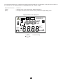
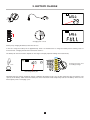
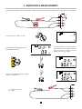
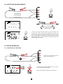
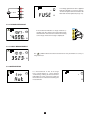
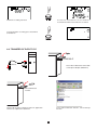
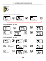
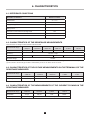
MICROHMMETER ENGLISH User’s manual C.A 6240 Thank you for purchasing a C.A. 6240 microhmmeter. To obtain the best service from your instrument: read this user manual carefully, comply with the precautions for use. WARNING, risk of DANGER! The operator must refer to this user’s manual whenever this danger symbol appears. Equipment protected by double insulation. Earth. The CE marking indicates conformity with European directives, in particular LVD and EMC. The rubbish bin with a line through it indicates that, in the European Union, the product must undergo selective disposal in compliance with Directive WEEE 2002/96/EC. This equipment must not be treated as household waste. Definition of measurement categories: Measurement category IV corresponds to measurements taken at the source of low-voltage installations. Example: power feeders, counters and protection devices. Measurement category III corresponds to measurements on building installations. Example: distribution panel, circuit-breakers, machines or fixed industrial devices. Measurement category II corresponds to measurements taken on circuits directly connected to low-voltage installations. Example: power supply to electro-domestic devices and portable tools. PRECAUTIONS FOR USE This device is compliant with safety standard IEC 61010-2-030 and the leads are compliant with IEC 61010-031, for voltages up to 50 V with respect to earth in category III. Failure to observe the safety instructions may result in electric shock, fire, explosion, and destruction of the instrument and of the installations. The operator and/or the responsible authority must carefully read and clearly understand the various precautions to be taken in use. Sound knowledge and a keen awareness of electrical hazards are essential when using this instrument. If you use this instrument other than as specified, the protection it provides may be compromised, thereby endangering you. Do not use the instrument on conductors likely to be connected to line power or on earth conductors that are not disconnected. Do not use the instrument if it seems to be damaged, incomplete, or poorly closed. Before each use, check the condition of the insulation on the leads, housing, and accessories. Any item of which the insulation is deteriorated (even partially) must be set aside for repair or scrapping. Check that the switch is set to OFF before plugging in the mains cord to recharge the battery of the instrument. OFF Respect the value and type of the fuse to avoid damaging the instrument and cancelling the warranty. Set the switch to OFF when the instrument is not in use. 2 Do not immerse the C.A 6240 microhmmeter in water. Use connection accessories which have an overvoltage category and service voltage greater than or equal to those of the measuring instrument (50 V Cat III). Use only accessories that comply with safety standards (IEC 61010-2-031). All troubleshooting and metrological checks must be performed by competent and accredited personnel. Attach one of the 5 specifications labels, with your appropriate language, on the inside of the lid. 3 CONTENTS 1. PRESENTATION........................................................................................................................................................................ 5 2. BATTERY CHARGE................................................................................................................................................................... 7 3. RESISTANCE MEASUREMENT............................................................................................................................................... 8 3.1. Measurement of a very low value.................................................................................................................................... 9 3.2. Repetitive measurements.............................................................................................................................................. 10 3.3. Error messages............................................................................................................................................................. 10 4. STORAGE OF RESULTS......................................................................................................................................................... 12 4.1 Storing............................................................................................................................................................................ 12 4.2. Read memory................................................................................................................................................................ 13 4.3. Erase memory............................................................................................................................................................... 13 4.4. Further information........................................................................................................................................................ 13 4.5. Automatic recording...................................................................................................................................................... 13 4.6. Transfer of data to PC................................................................................................................................................... 14 5. OTHER FUNCTIONS (SET-UP)............................................................................................................................................... 15 5.1. Complete erasure of memory........................................................................................................................................ 15 5.2. Programming the time................................................................................................................................................... 15 5.3. Programming the date................................................................................................................................................... 15 5.4. Programming of automatic stopping time..................................................................................................................... 16 5.5. Displaying the internal parameters of the instrument................................................................................................... 16 6. CHARACTERISTICS............................................................................................................................................................... 17 6.1. Reference conditions..................................................................................................................................................... 17 6.2. Characteristics of the resistance measurements.......................................................................................................... 17 6.3. Characteristics of the voltage measurements on the terminals of the resistance measured........................................ 17 6.4. Characteristics of the measurements of the current flowing in the resistance measured............................................ 17 6.5. Influences on the resistance measurement................................................................................................................... 18 6.6. Power supply................................................................................................................................................................. 18 6.7. Environmental conditions.............................................................................................................................................. 18 6.8. Characteristics of construction..................................................................................................................................... 19 6.9. Conformity to international standards........................................................................................................................... 19 6.10. Electromagnetic compatibility..................................................................................................................................... 19 7. MAINTENANCE....................................................................................................................................................................... 20 7.1. Servicing........................................................................................................................................................................ 20 7.2. Repair............................................................................................................................................................................ 20 8. WARRANTY............................................................................................................................................................................. 21 9. TO ORDER............................................................................................................................................................................... 22 9.1. Accessories................................................................................................................................................................... 22 9.2. Spares........................................................................................................................................................................... 22 4 1. PRESENTATION Transfer of data to PC Battery charge X02870 Protecting fuse Connection terminals Choice of range or SET-UP C1 P1 P2 C2 C.A 6240 MICROHMMETER START/STOP To start or stop the measurements MEM Store the measurement Automatic recording MR Read memory CLR E r a s u re o f t h e l a s t measurement recorded ±I Change of direction of current DISPLAY Display current/ voltage p and u during the memory and set-up functions 5 The C.A 6240 microhmmeter is a portable measuring instrument intended for the measurement of very low resistance values. It is enclosed in a site case and powered by a rechargeable battery with a built-in charger. Measurement functions : resistance Controls : 8-position switch, 5-key keypad, and 1 START/STOP button Display : LCD display unit, 100 x 57 mm, back-lit, having 2 simultaneous digital display levels Representation of the display unit ° _ P COM +I I HOLD OBJ. TEST AVG > < MEMMRCLR °C°F mV mA V µmΩ DC AC 2nd indicates flashing 6 2. BATTERY CHARGE OFF Charge OFF Charge Current battery capacity in %. Charging time: 3 h 30 Start by fully charging the battery before the first use. In the 10 A range, the battery life is approximately 1h20. It is therefore best to charge the battery before starting series of measurements. Charging must be done between 0 and 40°C. The battery life of the instrument depends on the range. To display it (before making the measurement): SET-UP 400 W 10mA 40 W 10mA 4000m W 100mA > 2s 400m W 1A Average battery life according to range 40m W 1A 4000µ W 10A DISPLAY OFF Charge Remaining battery life Following long-term storage, the battery may be completely discharged. In this case, the first charge may last several hours. The capacity of the battery and therefore the battery life of the instrument will be temporarily reduced. The battery will recover its initial capacity after 5 recharging cycles. 7 3. RESISTANCE MEASUREMENT 1) Connect the 2 cables to the 4 measurement terminals, then the 2 Kelvin clips to the object to be tested, which must not be live. C1 P1 P2 C2 SET-UP +I 400 Ω 10mA A 400 Ω 10mA 2) Set the switch to 400Ω - 10 mA. Ω +I 3) Start the measurement by pressing the START/STOP button. mA Ω 2nd SET-UP 400 Ω 10mA 40 Ω 10mA 4000m Ω 100mA 400m Ω 1A 40m Ω 1A 4000µ Ω 10A OFF Charge 4) Press the START/STOP button again to stop the measurement... If the measurement is too low, turn the switch to the next lower range and restart the measurement. Continue until the display shows at least 3 digits. START/STOP +I A START/STOP mΩ 2nd +I HOLD 2nd A mΩ C1 ...or disconnect one of the 2 clips. P1 P2 C2 8 The energy accumulated in an inductive component when a measurement is made on it must be released. You must never in any circumstances touch or disconnect the measurement leads until you have stopped making the measurement and waited at least ten seconds for all of the energy in the item tested to be dissipated. Failure to observe this precaution may result in the production of an arc, potentially hazardous for both the instrument and the operator. If the measurement is stopped by the disconnection of a clip, simply connecting it to another object starts another measurement, with no need to press the START/STOP key. +I In both cases, the last measurement made is displayed, along with the HOLD symbol. A HOLD mΩ 2nd DISPLAY _I AVG To display the voltage on the terminals of the resistance instead of the measurement current, press the DISPLAY key. mV A HOLD mΩ 3.1. MEASUREMENT OF A VERY LOW VALUE START/STOP START/STOP _I AVG µ Ω ±I _I HOLD AVG Reverse the direction of the current by pressing the ±I key and the instrument displays the average: R(+I) + R(-I) 2 This serves to eliminate any thermoelectric effect. A DISPLAY A RAVG = +I R(+I) +V R(+I) µ Ω 9 -I R(-I) -V R(-I) To display the values R(+I) and R(-I), press the DISPLAY key. 3.2. REPETITIVE MEASUREMENTS C1 P1 P2 C2 START/STOP +I A Ω +I A HOLD µ Ω Connect the clips to the first object to be measured. The measurement starts automatically. Withdraw the clips: the measurement stops and the result is displayed. Connect the clips to the second object to be measured. The measurement restarts automatically. And so on. After the last measurement, press the START/STOP button again. START/STOP 3.3. ERROR MESSAGES 3.3.1. PRESENCE OF A VOLTAGE C1 P1 P2 >7V If there is an external voltage on the device to be measured... C2 P +I ou V DC START/STOP 10 ...pressing the START/STOP button has no effect: the measurement is impossible. Remove the voltage to make the measurement. C1 > 20 V P1 If a voltage greater than 20 V is applied between terminals C1 and C2, the fuse on the front panel of the instrument will blow and must be replaced (see §7.1.2). +I A HOLD P2 Ω C2 3.3.2. RANGE OVERSHOOT SET-UP +I A > If the instrument indicates a range overshoot (> symbol), turn the switch to the next higher range and restart the measurement. Continue for as long as the range overshoot message is displayed. µ Ω 400 Ω 10mA 40 Ω 10mA 4000m Ω 100mA 400m Ω 1A 40m Ω 1A 4000µ Ω 10A OFF Charge 3.3.3. NOISY MEASUREMENT +I A The symbol indicates that the measurement is noisy and that its accuracy is not guaranteed. µ Ω 3.3.4 OVERHEATING ° +I If a measurement in the 10 A range lasts several minutes, it causes internal overheating, making all measurements impossible. It is then necessary to wait for the instrument to cool before resuming the measurements. 11 +I A Ω 4. STORAGE OF RESULTS Data storage is organised into objects (OBJ.), each of which can contain several tests (TEST). OBJ. corresponds to the object tested and each test corresponds to a measurement made on the object. The instrument can store 100 measurements. 4.1 STORING +I A HOLD µ Ω MEM Once the measurement is over, it can be recorded. Press the MEM key. +I OBJ. TEST MEM The instrument proposes the first free location in memory. If it is acceptable, execute a long press on the MEM key. MEM +I > 2s OBJ. TEST MEM MEM +I OBJ. TEST OBJ. TEST OBJ. TEST To change the number of the test or of the object, use the arrows. MEM +I OBJ. If the location chosen is already occupied, the instrument so indicates. But it is possible to overwrite the old measurement with the new one. TEST > 2s MEM MEM +I OBJ. TEST or MEM 12 To exit from the function without recording anything, press the MEM key. 4.2. READ MEMORY It is necessary first of all to stop the measurement by pressing the START/STOP button. +I OBJ. To read all tests containing a record. MR MR To change objects. TEST µ Ω To exit from the read memory function. MR 4.3. ERASE MEMORY To erase a record (read memory or not): CLR +I OBJ. CLR +I > 2s TEST µ Ω CLR OBJ. TEST CLR Use the arrows to select the test to be erased. The complete erasure of the memory is described in section 5.1. 4.4. FURTHER INFORMATION MR P MEM P +I +I OBJ. OBJ. TEST TEST 2nd Memory empty Memory full 4.5. AUTOMATIC RECORDING > 2s MEM P +I OBJ. TEST To choose the start location for recording. MEM AUTO > 2s MEM 13 MEM P +I OBJ. TEST HOLD To stop automatic recording, press the START/ STOP button. OBJ. TEST µ Ω START/STOP Automatic recording activated. MEM P +I At each new measurement, the test number is incremented and the measurement is recorded. +I A Ω START/STOP 4.6. TRANSFER OF DATA TO PC HX0056-Z X02870 First of all, install the driver of the USB/ serial optical adapter (HX0056-Z). Micro Ohmmeter Transfer Then install the “Micro Ohmmeter Transfer” application software as explained in readme.txt. To use “Micro Ohmmeter Transfer” , refer to the help function. 14 5. OTHER FUNCTIONS (SET-UP) SET-UP 400 Ω 10mA SET-UP 40 Ω 10mA 4000m Ω 100mA 400m Ω 1A 40m Ω 1A 4000µ Ω 10A OFF Charge 5.1. COMPLETE ERASURE OF MEMORY MEM MEM MEM >2s CLR >2s 5.2. PROGRAMMING THE TIME MEM >2s To change the minutes To change the hour >2s 5.3. PROGRAMMING THE DATE >2s To choose the date format: ddmm (European) mmdd (USA) To change the year To change the date To change the month 15 >2s 5.4. PROGRAMMING OF AUTOMATIC STOPPING TIME P P >2s To choose automatic powerdown select “ON”, if not, choose “OFF”. To adjust the On time: 5, 10, or 15 minutes. >2s 5.5. DISPLAYING THE INTERNAL PARAMETERS OF THE INSTRUMENT Configuration of the instrument >2s Serial number ° _ HOLD AVG 2nd Software version Date of last calibration 16 P COM +I I > < OBJ. TEST MEMMRCLR °C°F mV mA V µmΩ DC AC Lighting of all segments of the display unit >2s 6. CHARACTERISTICS 6.1. REFERENCE CONDITIONS Quantities of influence Reference values Temperature 23 ± 3 °C Relative humidity 45 to 55 % RH Supply voltage 6 V ± 0,2 V External voltage present on the terminals of the resistance being tested zero Inductance of the resistance being tested zero Electric field zero Magnetic field < 40 A/m 6.2. CHARACTERISTICS OF THE RESISTANCE MEASUREMENTS There must be no voltage on the element to be measured. Measurement range Resolution 53999 mW 4,00 39,99 mW 40,0 – 399,9 mW 400 – 3999 mW 4,00 – 39,99 W 40,0 – 399,9 W 1 mW 10 mW 100 mW 1 mW 10 mW 100 mW Accuracy Measurement current ± 0,25% ± 2 pt 10,2 A ± 2% (1) 1,02 A ± 2% No-load voltage 102 mA ± 2% 10,2 mA ± 2% (2) 4 to 6 V (1) With a nominal value of 10.2 A, the measurement current is at least 10 A whatever the charge condition of the battery. (2) The current is 10 mA only up to 300 Ω. If the battery is low, it can fall to as low as 8 mA. 6.3. CHARACTERISTICS OF THE VOLTAGE MEASUREMENTS ON THE TERMINALS OF THE RESISTANCE MEASURED 0,010 – 3,999 mV 4,00 – 39,99 mV 40,0 – 399,9 mV 0,400 – 3,999 V 4,00 – 4,70 V Resolution 1 mV 10 mV 100 mV 1 mV 10 mV Accuracy ± 0,5% ± 10 pt Measurement range ± 0,5% ± 1 pt 6.4. CHARACTERISTICS OF THE MEASUREMENTS OF THE CURRENT FLOWING IN THE RESISTANCE MEASURED 5,00 – 39,99 mA 40,0 – 399,9 mA 0,400 – 3,999 A 4,00 – 11,00 A Resolution 10 mA 100 mA 1 mA 10 mA Accuracy ± 0,5% ± 2 pt Measurement range ± 0,5% ± 1 pt 17 6.5. INFLUENCES ON THE RESISTANCE MEASUREMENT Quantities of influence Range of use Temperature Variation of the measurement Typical Maximum -10 to + 55 °C 0,1 %/10 °C 0,5 %/10 °C + 2pt 10 to 85 % RH @ 45°C 0,1 % 0,5 % + 2pt 5 to 7 V 2 pt 0,2%/ V + 2pt Series mode rejection, 50/60 U (AC) = (Rmeasured x I Hz (1) measurement) < 0,2% 2% + 1pt Common mode rejection, 50/60 Hz AC > 80 dB > 60 dB Relative humidity Supply voltage 0 to 50 V AC (1) Example: If the measured resistance is 1 mW and the measurement current is 10 A, an alternating voltage of 1 mV RMS in series with the resistance to be measured will induce an error of not more than 2%. 6.6. POWER SUPPLY The instrument is powered by a rechargeable 6 V 8.5Ah NiMH battery pack. This has many advantages : long life with small size and weight, the possibility of recharging your battery rapidly, a very small memory effect: you can recharge your battery rapidly, even if it is not fully discharged, without reducing its capacity, protection of the environment: no polluting materials such as lead or cadmium. The NiMH technology allows a limited number of charging/discharging cycles. The number depends on the conditions of use and on the charging conditions. Under optimum conditions, the number of cycles is 200. The instrument has 2 charging modes: rapid charging: the battery recovers 90% of its capacity in 3h; maintenance charging: this mode cuts in when the battery is very low and at the end of rapid charging. The battery life depends on the ranges used Number of measurements (1) 10 A range 850 1 A range 3 500 100 mA range 4 500 10 mA range 5 000 Instrument on standby or off battery life 4 to 6 months (1) established for measurements lasting 5s, every 25s. 6.7. ENVIRONMENTAL CONDITIONS Use indoors or outdoors. Range of use Storage (without battery) Altitude Degree of pollution - 10 to +55 °C - 40 to +70 °C < 2000 m 2 10 to 85 % RH 10 to 90 % RH For long-term storage (2 years) with the battery, conditions must not depart from the range -20 to +30°C and 85% RH; otherwise, the battery life will be degraded. For short-term storage (1 month), the temperature can reach 50°C. 18 6.8. CHARACTERISTICS OF CONSTRUCTION Overall dimensions of the instruments (L x W x H): 273 x 247 x 176 mm Mass: approximately 4.5 kg IP 53 per NF EN 60529 IK 04 per NF EN 50102 6.9. CONFORMITY TO INTERNATIONAL STANDARDS Electrical safety as per EN 61010-1 Measurement according to EN 61557 parts 1 and 4. Safety level categories: measurement category III, 50V with respect to earth, 500V differential between terminals, and 300V cat II on the charger input 6.10. ELECTROMAGNETIC COMPATIBILITY Emissions in a residential environment and immunity in an industrial setting compliant with EN 61326-1. 19 7. MAINTENANCE Except for the fuse, the instrument contains no parts that can be replaced by personnel who have not been specially trained and accredited. Any unauthorized repair or replacement of a part by an “equivalent” may gravely impair safety. 7.1. SERVICING 7.1.1. RECHARGING THE BATTERY g Recharge the battery (see §2) The battery must be replaced by Manumesure or by a repairer approved by Chauvin Arnoux. Only fit the battery recommended by the manufacturer. Replacing the battery does not cause a loss of the data in memory. However, the date and time must be reprogrammed (see § 5.2 and 5.3). 7.1.2. REPLACEMENT OF THE FUSE +I HOLD A OFF Ω FF 12,5 A - 500 V - 6,3 x 32 mm - 20 kA 7.1.3. CLEANING Use a soft cloth, dampened with soapy water. Rinse with a damp cloth and dry rapidly with a dry cloth or forced air. Do not use alcohol, solvents, or hydrocarbons. OFF 7.1.4. METROLOGICAL CHECK Like all measuring or testing devices, the instrument must be checked regularly. This instrument should be checked at least once a year. For checking and calibration, contact one of our accredited metrology laboratories (information and contact details available on request), at our Chauvin Arnoux subsidiary or the branch in your country. 7.1.5. UPGRADING THE SOFTWARE OF THE INSTRUMENT With a view to providing, at all times, the best possible service in terms of performance and technical upgrades, Chauvin Arnoux invites you to update the embedded software of the device by downloading the new version, available free of charge on our web site. Our site: http://www.chauvin-arnoux.com Sign in and open your account. Then go to “Software support space”, then “Freely available software”, then “C.A 6240”. Connect the device to your PC using the USB cord provided. 7.2. REPAIR For all repairs before or after expiry of warranty, please return the device to your distributor. 20 8. WARRANTY Except as otherwise stated, our warranty is valid for twelve months starting from the date on which the equipment was sold. Extract from our General Conditions of Sale provided on request. The warranty does not apply in the following cases: Inappropriate use of the equipment or use with incompatible equipment; Modifications made to the equipment without the explicit permission of the manufacturer’s technical staff; Work done on the device by a person not approved by the manufacturer; Adaptation to a particular application not anticipated in the definition of the equipment or not indicated in the user’s manual; Damage caused by shocks, falls, or floods. 21 9. TO ORDER C.A 6240 ................................................................................................................................................................... P01143200 The C.A 6240 is delivered in a cardboard box with a carrying bag of accessories containing: one set of two 10 A Kelvin clips with a 3 m cable, one 2 m power cord, one optical / USB communication cable, “Micro Ohmmeter Transfer” software, simplified operating manuals (1 per language), one user manuals on CD-ROM (1 file per language). 9.1. ACCESSORIES GB power cord 2 m long ........................................................................................................................................... P01295253 Set of 2 double probe tips ......................................................................................................................................... P01101782 Set of 2 miniature Kelvin clips.................................................................................................................................... P01101783 C A 846 thermo-hygrometer ..................................................................................................................................... P01156301Z Optical / RS communication cable ............................................................................................................................ P01295252 9.2. SPARES Set of 10 FF 12 fuses, 5 A – 500 V - 6.3 x 32 mm ..................................................................................................... P01297091 Set of two 10 A Kelvin clips with 3 m cable .............................................................................................................. P01101794 2P EURO power cord 2 m long ................................................................................................................................ P01295174 Standard carrying bag ............................................................................................................................................... P01298066 Optical / USB communication cable ......................................................................................................................... HX0056-Z 22 23 11 - 2014 Code 692008C02 - Ed. 1 DEUTSCHLAND - Chauvin Arnoux GmbH Straßburger Str. 34 - 77694 Kehl / Rhein Tel: (07851) 99 26-0 - Fax: (07851) 99 26-60 SCHWEIZ - Chauvin Arnoux AG Moosacherstrasse 15 - 8804 AU / ZH Tel: 044 727 75 55 - Fax: 044 727 75 56 UNITED KINGDOM - Chauvin Arnoux Ltd Unit 1 Nelson Ct - Flagship Sq - Shaw Cross Business Pk Dewsbury, West Yorkshire - WF12 7TH Tel: 01924 460 494 - Fax: 01924 455 328 CHINA - Shanghai Pujiang Enerdis Instruments Co. Ltd 3 Floor, Building 1 - N° 381 Xiang De Road Hongkou District - 200081 SHANGHAI Tel: +86 21 65 21 51 96 - Fax: +86 21 65 21 61 07 ITALIA - Amra SpA Via Sant’Ambrogio, 23/25 - 20846 Macherio (MB) Tel: 039 245 75 45 - Fax: 039 481 561 ESPAÑA - Chauvin Arnoux Ibérica S.A. C/ Roger de Flor, 293 - 1a Planta - 08025 Barcelona Tel: 90 220 22 26 - Fax: 93 459 14 43 ÖSTERREICH - Chauvin Arnoux Ges.m.b.H Slamastrasse 29/2/4 - 1230 Wien Tel: 01 61 61 9 61-0 - Fax: 01 61 61 9 61-61 MIDDLE EAST - Chauvin Arnoux Middle East P.O. BOX 60-154 - 1241 2020 JAL EL DIB (Beirut) - LEBANON Tel: (01) 890 425 - Fax: (01) 890 424 SCANDINAVIA - CA Mätsystem AB Sjöflygvägen 35 - SE 18304 TÄBY Tel: +46 8 50 52 68 00 - Fax: +46 8 50 52 68 10 USA - Chauvin Arnoux Inc - d.b.a AEMC Instruments 200 Foxborough Blvd. - Foxborough - MA 02035 Tel: (508) 698-2115 - Fax: (508) 698-2118 http://www.chauvin-arnoux.com 190, rue Championnet - 75876 PARIS Cedex 18 - FRANCE Tél. : +33 1 44 85 44 85 - Fax : +33 1 46 27 73 89 - [email protected] Export : Tél. : +33 1 44 85 44 38 - Fax : +33 1 46 27 95 59 - [email protected]