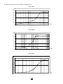
1
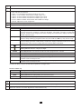
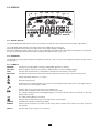
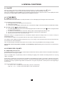
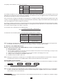
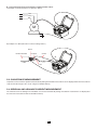
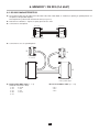
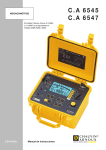
MEGOHMMETERS ENGLISH User’s manual C.A 6545 C.A 6547 Thank you for purchasing a C.A. 6545 or C.A. 6547 megohmmeter. To obtain the best service from your instrument: read this user manual carefully, comply with the precautions for use. WARNING, risk of DANGER! The operator must refer to this user’s manual whenever this danger symbol appears. Equipment protected by double insulation. WARNING! Risk of electric shock. The voltage on the parts marked with this symbol may be dangerous. For safety reasons, this symbol is displayed when such a voltage is generated. Earth. The CE marking indicates conformity with European directives, in particular LVD and EMC. The rubbish bin with a line through it indicates that, in the European Union, the product must undergo selective disposal in compliance with Directive WEEE 2002/96/EC. This equipment must not be treated as household waste. Definition of measurement categories: Measurement category IV corresponds to measurements taken at the source of low-voltage installations. Example: power feeders, counters and protection devices. Measurement category III corresponds to measurements on building installations. Example: distribution panel, circuit-breakers, machines or fixed industrial devices. Measurement category II corresponds to measurements taken on circuits directly connected to low-voltage installations. Example: power supply to electro-domestic devices and portable tools. PRECAUTIONS FOR USE This device is compliant with safety standard IEC 61010-2-030 and the leads are compliant with IEC 61010-031, for voltages up to 1000 V with respect to earth in category III. Failure to observe the safety instructions may result in electric shock, fire, explosion, and destruction of the instrument and of the installations. The operator and/or the responsible authority must carefully read and clearly understand the various precautions to be taken in use. Sound knowledge and a keen awareness of electrical hazards are essential when using this instrument. If you use this instrument other than as specified, the protection it provides may be compromised, thereby endangering you. Do not use the instrument on networks of which the voltage or category exceeds those mentioned. Do not use the instrument if it seems to be damaged, incomplete, or poorly closed. Before each use, check the condition of the insulation on the leads, housing, and accessories. Any item of which the insulation is deteriorated (even partially) must be set aside for repair or scrapping. Use personal protection equipment systematically. Use only the accessories delivered with the instrument. Respect the value and type of the fuse (see § 8.1.2) to avoid damaging the instrument and cancelling the warranty. Set the switch to OFF when the instrument is not in use. The battery must be charged before metrological tests. All troubleshooting and metrological checks must be performed by competent and accredited personnel. 2 CONTENTS 1. PRESENTATION........................................................................................................................................................................ 4 1.1. The megohmmeters........................................................................................................................................................ 4 1.2. The accessories (for the C.A 6547 only).......................................................................................................................... 4 2. DESCRIPTION........................................................................................................................................................................... 5 2.1. Casing............................................................................................................................................................................. 5 2.2. Display............................................................................................................................................................................. 7 3. MEASUREMENT FUNCTIONS................................................................................................................................................. 8 3.1. AC/DC voltage................................................................................................................................................................. 8 3.2. Insulation measurements................................................................................................................................................ 8 4. SPECIAL FUNCTIONS............................................................................................................................................................ 10 4.1. 2nd key ......................................................................................................................................................................... 10 4.2. V-TIME/ key.............................................................................................................................................................. 10 4.3. R-DAR-PI-DD / R(t) key................................................................................................................................................ 10 4.4. / ALARM key .......................................................................................................................................................... 13 4.5. u / SMOOTH key.......................................................................................................................................................... 13 4.6. pq key......................................................................................................................................................................... 13 4.7. SET-UP Function (device configuration)........................................................................................................................ 13 5. USE.......................................................................................................................................................................................... 17 5.1. Measurement procedure............................................................................................................................................... 17 5.2. Insulation measurement................................................................................................................................................ 17 5.3. Capacitance measurement........................................................................................................................................... 18 5.4. Residual and leakage current measurement................................................................................................................. 18 6. MEMORY / RS 232 (C.A 6547)............................................................................................................................................... 19 6.1. RS 232 Characteristics.................................................................................................................................................. 19 6.2. Recording/PLAYBACK of stored values (MEM/MR key)............................................................................................... 20 6.3. Printing measured values (PRINT/PRINT MEM key) (C.A 6547).................................................................................. 20 6.4. Printing with series-parallel adapter.............................................................................................................................. 22 7. SPECIFICATIONS.................................................................................................................................................................... 23 7.1. Reference conditions..................................................................................................................................................... 23 7.2. Characteristics per function ......................................................................................................................................... 23 7.3. Power Supply................................................................................................................................................................ 26 7.4. Environmental parameters............................................................................................................................................ 27 7.5. Construction specifications........................................................................................................................................... 27 7.6. Compliance with international standards...................................................................................................................... 27 7.7. Variations in operating range......................................................................................................................................... 28 8. MAINTENANCE....................................................................................................................................................................... 29 8.1. Servicing........................................................................................................................................................................ 29 8.2. Metrological check........................................................................................................................................................ 29 8.3. Repair............................................................................................................................................................................ 29 9. GUARANTEE........................................................................................................................................................................... 30 10. TO ORDER............................................................................................................................................................................. 31 10.1. Accessories................................................................................................................................................................. 31 10.2. Spare parts.................................................................................................................................................................. 31 3 1. PRESENTATION 1.1. THE MEGOHMMETERS The C.A 6545 and C.A 6547 megohmmeters are portable units, fitted into a rugged construction site casing with cover, operating on battery or line power. They are used to measure: voltages, insulation, capacitance. These megohmmeters help to ensure the safety of electrical installations and equipment. Their operation is controlled by microprocessor for the acquisition, processing, measurement display, storage and printing of results (C.A 6547). They offer a wide range of advantages such as: digital filtering of insulation measurements, automatic voltage measurement, automatic detection of the presence of AC or DC external voltage on terminals, before or during the measurements, which inhibits or stops the measurements, threshold programming, to trigger alarms using audible beeps, the timer for measurement time checks, protection of the device by fuse, with detection of defective fuses, operator safety by means of automatic discharge of the residual high voltage on the equipment tested, automatic power save mode of the device to save battery power, indication of battery charge condition, a large backlit LCD screen with a wide range of indicators making it very easy for the user to read. The C.A 6547 integrates the following additional functions: Memory (128 kb), real time clock and serial interface, PC control of the device (using PC software, optional), Printing in RS 232 or Centronics mode. 1.2. THE ACCESSORIES (FOR THE C.A 6547 ONLY) 1.2.1. PC SOFTWARE (OPTIONAL) This PC software is used for: recovering stored data, plotting the insulation resistance versus the test voltage application time, R(t), printing customised test protocols in accordance with user needs, creating text files to use spreadsheets (ExcelTM ...), configuring and controlling the unit via the RS 232, 1.2.2. SERIAL PRINTER (OPTION) This compact printer is used to print the measurement results directly in the field, whether stored or not. 1.2.3. SERIAL-PARALLEL ADAPTER (OPTION) The optional RS232/Centronics adapter converts the serial interface (RS232) into a parallel printer interface (Centronics), enabling direct printing of all measurements on A4-format office printers, without having to use a personal computer. 4 2. DESCRIPTION 2.1. CASING ➇ ➆ 110-230V 50/60 Hz 20 VA max INTERFACE ➅ SET-UP Var 50-5000V ➁ > 2500V 5000V 10T Ω 2500V 10T Ω FF 0.1A 380V-10kA 5x20mm ➂ 1000V 4T Ω 500V 2T Ω ➀ OFF V/ T IME SMOOTH ALARM PRINT R-DAR-PI-DD MEM 1000V CAT III ( 2500V ) 2nd MR PRINT MEM R(t) START/STOP C.A 6547 MEGOHMMETER ➄ 5 ➃ ➀ ➁ ➂ 3 safety terminals, Ø 4 mm, marked: "+", "G" and "-". ➃ ➄ 1 yellow START / STOP push button: start / stop of measurement. Access to terminal "G" protective fuse. 7-way rotary switch: OFF: switches off unit power 500 V - 2 TΩ: insulation measurement at 500 V, up to 2 TΩ 1000 V - 4 TΩ: insulation measurement at 1000 V, up to 4 TΩ 2500 V - 10 TΩ: insulation measurement at 2500 V, up to 10 TΩ 5000 V - 10 TΩ: insulation measurement at 5000 V, up to 10 TΩ Var. 50 - 5000 V: insulation measurement with variable test voltage SET-UP: adjustment of unit configuration 6 keys (C.A 6545) or 8 keys (C.A 6547) made of elastomer, each having a main function and a secondary function: 2nd Selection of the second function (in yellow Italics above each key). R-DAR-PI-DD Primary function: before the insulation measurements, selection of required measurement type: normal measurement, calculation of dielectric absorption ratio (DAR), calculation of polarisation index (PI) or Dielectric Discharge test DD. After or during the measurements, display of R, DAR, PI, DD and capacitance (µF). R(t) Secondary function: display/no display of intermediate values of insulation resistance, test voltage and time stamp, following a programmed time test (the V-TIME and pq keys may also be used). V / TIME Primary function: In insulation, display of elapsed time from the beginning of measurement, then of exact voltage generated. In MR (memory recall) mode, display of the date and time of the stored measurement, of the exact test voltage and of the memory address OBJ:TEST. Secondary function: activation/deactivation of “programmed time test” mode. Primary function: ON/OFF of display backlight. ALARM u SMOOTH Secondary function: activation/deactivation of alarms programmed in SET-UP. Primary function: Select a parameter for modification. Secondary function: ON/OFF for display smoothing during insulation measurement. p Primary function: increments the displayed flashing parameter. Browse the list of intermediate insulation results in the R(t) function. q Secondary function: decrements the flashing parameter displayed. Browse the list of intermediate insulation results in the R(t) function. If the p and q keys are pressed and held, the parameter changes faster. On the C.A 6547 only MEM MR PRINT PRINT MEM ➅ ➆ ➇ Primary function: storage of measured values. Secondary function: recall of stored data. Primary function: immediate printing of measurement result. Secondary function: printing of memory content. Backlit liquid crystal display. Socket for connection to AC network (direct operation on AC network/battery recharge). Male connector RS 232 serial interface connector (9-pin) for connection to a PC or printer (C.A 6547 only). On the C.A 6545, this connector is used for adjustments of the instrument only. 6 2.2. DISPLAY 0.1M 1M 10M 100M 1G 10G 100G 1T min sec MEM MR PI DARDD 2 nd OBJ. TEST DC VAC µA nA µF ALARM SMOOTH REMOTE 2.2.1. DIGITAL DISPLAY The main digital display indicates the values for insulation measurement values: resistance, DAR PI, DD or capacitance). The small digital display indicates the voltage measured or applied by the instrument. During the insulation measurement, the elapsed time or the output voltage is displayed. After the recording of a group of data (C.A 6547), the small display also indicates the date and time in MR (Memory recall) mode. It is also used to indicate the memory address using the OBJ:TEST number. (see § 2.2.3). 2.2.2. BARGRAPH The bargraph is active during insulation measurement (0.1 MΩ to 1 TΩ). It is also used, to indicate the battery charge, and the memory space. 2.2.3. SYMBOLS MEM/MR indicates the storage (MEM) or memory reading (MR) operations (C.A 6547). OBJ:TEST Memory address (C.A 6547): the number is displayed above, on the small digital display. COM Indicates that the instrument is sending data to the printer via the interface (C.A 6547). DAR/PI/DD indicates the mode chosen before the insulation measurement or the results of these measurements. Voltage generated dangerous, U > 120 Vdc. External voltage present. Activation of the "Programmed-time test" mode or, on the SET-UP position of the switch, clock adjustment (C.A 6547). Flashes for each sample recorded. 2 nd Indicates that the secondary function of a key will be used. Indicates that the battery is low and must be recharged (see § 8). The voltage is displayed on the small digital display for 2 seconds when the device is switched on. The main display indicates “bat”. The audio warning (buzzer) is activated. Indicates that the automatic power save mode function is deactivated. SMOOTH Smoothing of insulation measurement display. REMOTE Remote control via interface (C.A 6547). In this mode, all keys and the rotary switch are inactive, except the OFF position. FUSE -G- Indicates that the fuse of input “G” is defective. 7 3. MEASUREMENT FUNCTIONS 3.1. AC/DC VOLTAGE Any rotation of the switch on an insulation position sets the unit to automatic AC / DC voltage measurement. The voltage is measured continuously and indicated on the small display. The start of the insulation measurements is inhibited if an excessively high external voltage is present on the terminals, before pressing START. Also, if an excessively high parasitic voltage is detected during these measurements, they are automatically stopped and the voltage is indicated (see § 3.2). Switching between the AC and DC modes is done automatically, in AC mode the RMS value is indicated. 3.2. INSULATION MEASUREMENTS When the switch is rotated to an insulation position, the main display shows “tESt” and the small display shows the selected test voltage for a short time. If the test voltage is limited to a smaller value than selected, because of a test voltage limit set in SET-UP (see § 4.7.6), “LIM” is shown (instead of “tESt”) together with the actual voltage value. After that the main display shows “- - - - MΩ” and the small display shows the voltage present at the + and - terminals of the instrument. If, when the START key is pressed, the external voltage present at the terminals of the unit is higher than the value defined by the equation below, the insulation measurement is not triggered an audible warning signal sounds and the main display shows the message “> diSt” for a short time, then the instrument returns to automatic voltage measurement. Upeak > 0,4 x dISt x Un with: Upeak: peak or DC external voltage present on unit terminals dISt: coefficient defined in the set-up menu (adjustable to 0.03 - 0.10 - 0.20 - default value: 0.03) Un: test voltage chosen for insulation measurement If the external voltage at the terminals of the unit is less than the value defined previously, the insulation measurement is authorised. Pressing the START key immediately triggers the measurement. The value of the measurement is displayed on the main digital display and on the bargraph. There is a beep every 10 seconds to indicate that a measurement is in progress. If the voltage generated might be dangerous (> 120 V), the symbol is displayed. If, during the insulation measurements, an external voltage higher than the value defined by the relation below is detected, the measurement is aborted. The symbol flashes and the external voltage value is displayed on the small digital display. U peak > (dISt + 1.1) Un Note: Adjustment of the dISt factor optimises the measurement settling time. If there is no parasitic voltage present, the dISt factor may be adjusted to the smallest value (0,03) to obtain the shortest possible settling time for the measurement. If a significant parasitic voltage is present, the dISt factor may be increased so that the measurement is not interrupted or even made possible in the first place. This means optimisation of the settling time in the presence of the parasitic voltage. If the measurements are unstable, it is possible to use the SMOOTH function (see § 4.5). Pressing on the V-TIME key during the measurement alternately displays the measurement time and the exact voltage generated on the small display (see § 4.2). The stopping of the measurement is caused by pressing the STOP key. After the measurement stops, the main result remains displayed. It is possible to scroll through all the other results available on the main display using the R-DAR-PI-DD key. This key may also be used before the triggering of the measurement (see § 4.3). If the "Programmed time test" (see § 4.2 and 4.3). mode was selected, the R(t) key is used to access all the intermediate results stored automatically If the ALARM function is activated, a buzzer will sound as soon as the measurement exceeds or falls below the programmed threshold in the SET-UP configuration menu (see § 4.4). 8 Display of values after a measurement The indications below may be displayed: R-DAR-PI-DD key V-TIME key Small display Small display if the MR key is activated (C.A 6547) Resistance DAR PI DD 1 duration (min. sec) duration (min. sec) duration (min. sec) duration (min. sec) date, time, test voltage, OBJ:TEST date, time, test voltage, OBJ:TEST date, time, test voltage, OBJ:TEST date, time, test voltage, OBJ:TEST Current duration (min. sec) Capacitance 2 R(t) duration (min. sec) Main display last test voltage 1: The value of DD is displayed only one minute after the measurement stops. 2: The capacitance measurement (µF) is displayed only after the measurement stops and the circuit has been discharged. 9 4. SPECIAL FUNCTIONS 4.1. 2nd KEY This key is used to select the secondary functions of the function keys. It is always related to the 2nd symbol. This symbol disappears as soon as the selected function key is pressed, unless the q key is activated. In this case, it disappears only if the 2nd key is pressed again or if other function keys are pressed. This is used to rapidly decrement the parameters using the q key without having to press the 2nd key each time. 4.2. V-TIME/ KEY V-TIME primary function This key is used to show all available secondary information on the small display, both during and after measurement. In the insulation measurement function: Time elapsed since the beginning of the measurement, Measurement voltage, In memory recall mode (MR) (C.A 6547): date, time, measurement voltage, measurement duration and OBJ:TEST number. Secondary function (Programmed-time test) The small display shows the measurement duration programmed in the SET-UP, the symbol is ON. Pressing the START key starts the measurement. By default, the measurement lasts 30 minutes, but this value can be changed in the SET-UP menu. As soon as the measurement has started, the small display decrements the remaining time. When this time reaches zero, measurement stops. During the running of a programmed-time test, intermediate samples (resistance/voltage values as a function of time) are automatically stored. The time between samples is 30 s by default, but this value may be changed in the SET-UP menu. The samples may be displayed using the R(t) function (see § 4.3) as long as a new measurement has not been launched. They are erased at each new measurement. They are automatically stored with the final value of the resistance when using the MEM function (storage) (C.A 6547). If the position of the rotary switch is modified, or if the STOP key is pressed during the measurement, the measurement is aborted. 4.3. R-DAR-PI-DD / R(t) KEY R-DAR-PI-DD primary function The R-DAR-PI-DD key is used to calculate automatically the Polarisation Index (PI) and the Dielectric Absorption Ratio (DAR) or perform a Dielectric Discharge test (DD). These PI and DAR values are particularly useful for monitoring the ageing of the insulation of rotating machines or very long cables, for example. On this type of component, the measurement is disturbed at the beginning by parasitic current flows (capacitive load current, dielectric absorption current) which decrease with time. To measure exactly the representative leak current of the insulation, it is therefore necessary to perform long duration measurements, to by-pass the parasitic currents present at the beginning of measurements. Then the PI or DAR ratios are calculated: PI* = R 10 min / R 1 min (2 values to be noted during a 10-min. measurement) DAR = R 1 min / R 30 s (2 values to be noted during a 1-min. measurement) 10 The quality of the insulation is a function of the results. DAR PI Condition of insulation <1 <2 Insufficient or even dangerous < 1,6 <4 Good > 1,6 >4 Excellent < 1,25 For multilayer insulation, if one of the layers is defective but if all the others show strong resistance, the calculation of the PI and PAR ratios is not sufficient to show up this type of problem. It is therefore necessary to supplement the PI and DAR indications by a dielectric discharge test used to calculate the DD term. This test measures the dielectric absorption of heterogeneous or multilayer insulation while ignoring the parallel-surface leak currents. It consists of applying a test voltage for a period sufficient to electrically “charge” the insulation to be measured (a typical value is the application of a 500 V voltage for 30 minutes). An ordinary insulation measurement or a programmed-time test is done for the desired duration and at the desired test voltage. When ending the insulation measurement the test object is discharged fast and the capacitance is measured. After one minute the residual current through the test object is measured. The term DD is then computed from the equation below: DD = current measured after 1 minute (mA) test voltage (V) x capacitance measured (F) The indication of the insulation quality as a function of the resulting value is as follows: DD value Insulation quality 7 < DD Very bad 4 < DD < 7 Bad 2 < DD < 4 Doubtful DD < 2 Good insulation Note: The dielectric discharge test is particularly suited for the insulation measurement of rotating machines and in general for the insulation measurement of heterogeneous or multilayer insulation containing organic materials. Utilisation of the R-DAR-PI-DD function During or after a measurement, the R-DAR-PI-DD key is used to scroll through the values: DAR (if measurement > 1 min) PI 3 (if measurement > 10 min) DD can only be calculated 1 mn after the end of the insulation measurement and circuit discharge, and only if it was selected before beginning the measurement Capacitance in µF (only after the stopping of the measurement and the discharging of the circuit) Leakage current circulating in the installation in µA or nA Insulation resistance in MΩ or GΩ or TΩ Note: During the measurement, the DAR value is not available if DD was preselected before the measurement. During the measurement the value PI is not available if DAR or DD was preselected before the measurement. Automatic DAR or PI measurement: If the R-DAR-PI-DD key is actuated during the voltage measurement before the start of a measurement, the display is as follows: - - - - MΩ ↑ → DAR - - - - → PI - - - - → DD - - - - and the value of the input current (between terminals "+" and "-") is indicated. Note: The input current may be a depolarisation current resulting from an earlier insulation measurement. It is recommended to start a new DAR and PI measurement after the current has dropped to a negligible value (on the order of 100 pA) to avoid variations on these measurements. 3: For the PI calculation, the 10 and 1 minute times can be modified in the SET-UP menu, so to adapt to any normative changes or specific applications. 11 Depending on the choice (DAR, PI or DD), here is the measurement procedure: a) DAR: press START → the DAR symbol flashes and the display indicates “- - - -” as long as the calculation of the coefficient is impossible (t < 1 min). For example: DAR - - - - After 1 min. the measurement stops, the DAR symbol becomes steady and the main display automatically shows the DAR value if the calculation was possible. The R-DAR-PI-DD key may be used during and after the measurement to see the insulation measurement performed, but it does not provide the PI value, since the measurement did not last long enough. b) PI: press START → the PI symbol flashes and the display indicates “- - - -” as long as the calculation of the coefficient is impossible (t < 10 min). For example: PI - - - - After 10 min. the measurement stops, the PI symbol becomes steady and the main display automatically shows the PI value if the calculation was possible. During and after the measurement, the R-DAR-PI-DD key is used to display the DAR (after 1 min), the PI (after 10 min.) and the insulation measurement. c) DD: press START → the DD symbol flashes and the display indicates “- - - -” as long as the calculation of the coefficient is impossible (insulation-measurement time + 1 min.). For example: DD - - - - 1 min. after the measurement stops, the DD symbol becomes steady, the display automatically shows the value of DD if the calculation was possible. Therefore:if the measurement lasts 1 minutes if the measurement lasts 10 minutes and 1 minute after the end of the measurement → DAR → PI → DD Note: If, during the measurement of DAR, PI, or DD, whether automatic or not, there is a strong external disturbance, or if the insulation resistance exceeds the device’s measuring ranges, the measurement of DAR or PI is aborted and the following is shown on the display: DAR ou or PI In such case the measurement provides no result for DAR or PI. A capacitance parallel to the insulation resistance extends the settling times of the measurements. This can affect or even inhibit the measurement of DAR or PI (depending on the time set in SET-UP for recording the first resistance value). The following table shows typical values for the capacitance parallel to the insulation resistance, at which a successful DAR or PI measurement is still possible. The display of the DD value is: unknown (- - - -) if C < 1 nF or Idd < 100 pA known and flashing if 1 nF ≤ C < 10 nF and 100 pA ≤ Idd < 1 nA known and steady if C ≥ 10 nF and Idd ≥ 1 nA (with C = measured capacitance and Idd = current measured after 1 minute) Secondary function R(t) The R(t) key is used to access the intermediate insulation resistance values measured as a function of time, after a measurement in “Programmed-time test” mode (see § 4.2). The time between each stored samples is programmed in the SET-UP configuration menu. This function is also available on model C.A 6545 that has no RAM for the storage of measured data, or interface to recover this data from the instrument on a PC. After pressing the R(t) key, the instrument switches to display mode: the small display indicates a time of 00:30 (if the sampling frequency is 30 s) the main display indicates the corresponding value R. 12 The V-TIME key is used to alternate between time and voltage (on the small display), with the value R on the main display. The pq key is used to scroll through all the samples stored during the measurement. This makes it possible to note the elements for an R(t) and U(t) diagram. It is therefore possible to perform, on-site, an R(t) analysis with no printer or PC. A new press of the R(t) key, will exit the function. 4.4. / ALARM KEY Primary function This function is used to activate or deactivate the backlight. Secondary function ALARM Activation/deactivation of the ALARM function. The corresponding symbol is displayed when activated. If this function is active and the limit programmed in the SET-UP menu is exceeded or fallen below during the measurement, the ALARM symbol will flash and the buzzer (if activated) will sound continuously. It is possible to program a different limit for each test voltage, the limits will be stored even if the instrument is switched off. 4.5. u / SMOOTH KEY Primary function u Used to select a parameter for modification – the active parameter flashes. It may be modified using the pq key (see § 4.6). Secondary function SMOOTH Used to activate a digital filter for insulation measurements. It affects only the display (which is smoothed) and not the measurements. This function is useful in case of high instability of the displayed insulation values, caused by a strong capacitive component of the part to be tested, for example. The time constant for this filter is approximately 20 seconds. 4.6. pq KEY This function is used to modify the flashing parameters displayed, or to consult the R(t) values (see § 4.3). In general, two figures (day, month, hour, min., sec., OBJ:TEST) flash. The p and q functions have a "wraparound" mode: when the upper or lower modification limit is reached, the parameter to be modified automatically jumps to the other limit. . Primary function p: A brief press increments the displayed number by one unit. A longer pressure on this key will cause fast incrementation. Secondary function q: A brief press decrements the displayed number by one unit. A long press, will cause rapid decrementation. Contrary to all the secondary functions of the other keys, it is not necessary in this case to press the 2nd key each time to access the function q. The 2nd symbol remains displayed and therefore valid (for the function q only) as long as the user does not deactivate it by pressing the 2nd key again or another key. 4.7. SET-UP FUNCTION (DEVICE CONFIGURATION) This function, located on the rotary switch, is used to change the configuration of the device by accessing directly the parameters to be modified. After turning the rotary switch to the SET-UP position: all the segments of the display are activated for 1 second, the number of the software version is displayed the serial number of the device is displayed PUSH then appears on the small display and btn on the main display, to prompt you to press a key. The SET-UP function is then used to access directly the parameters to be modified, by pressing the corresponding key: After pressing a key, the figures or symbols corresponding to the function selected appear on the screen. The modifiable figures or symbols will flash. The normal modification procedure using the u and pq keys must be used. All the parameters are recorded immediately and permanently. 13 The following table defines the active keys in the SET-UP function and the corresponding display, with the possible adjustment ranges. Parameters to be modified Display Control key Test duration, in “Programmedtime test" mode 1nd and 2nd time for PI calculation Time between samples in “Programmed-time test” mode R-DAR-PI-DD main small symbols values tESt 30: 00 min. sec 01:00 - 59:59 first period (01:00) min: sec 00:30 - 59:59 00: 30 min: sec 00:05 - 30:00 second period (10:00) R(t) Limit for 500 V - 2 TΩ ALARM 500 kΩ 500 V ALARM < 30 k-2 TΩ and >< Limit for 1000 V - 4 TΩ ALARM (2 press) 1 MΩ 1000 V ALARM < 100 k-4 TΩ and >< Limit for 2500 V - 10 TΩ ALARM (3 press) 2.5 MΩ 2500 V ALARM < 300 k-10 TΩ and >< Limit for 5000 V - 10 TΩ ALARM (4th press) 5 MΩ 5000 V ALARM < 300 k-10 TΩ and >< Limit for Var-50/5000 V ALARM (5 press) 5 MΩ Set ALARM < 10 k-10 TΩ and >< Time nd rd th V-TIME Date (Europe version) V-TIME (2nd press) 17.03 Version: USA, Europe V-TIME (3 press) USA/Euro MEM then MEM (2 s) cLr Erase memory Selective deletion of memory Baud rd MEM then u and pq and FrEE / OCC MEM (2 s) PRINT 9600 Buzzer Auto cut-off (2nd press) 12:55 hour (00-23) minute (00-59) 2000 dd.mm.yyyy USA/Euro ALL MEM OBJ:TEST Number MEM 00 - 99 300 - 9600 or "parallel" bAUd On On / OFF On On / OFF (3rd press) then START DFLt SEt Dielectric test voltage (4th press) SEt 100 V V 40 - 5100 V Disturbance Limit voltage (5th press) 0.03 U dISt V 0.03 / 0.10 / 0.20 Automatic range (6th press) Auto rAnG Auto/1/2/3 Test voltage locking (7th press) oFF 1000 V On / OFF 40 - 5100 V Configuration by default The values shown in this table, in the “main display” and “small display” columns, are default values programmed at the factory. In case of mistaken modification, it is possible to restore them: see § 4.7.3. 14 4.7.1. MEMORY DELETION In SET-UP, press the MEM key: The MEM symbol flashes, ALL is shown flashing on the small display, The main display indicates cLR. To delete the entire memory, press again on the MEM key for 2 seconds: The MEM symbol is displayed steady, ALL is shown constant on the small display, The main display indicates FrEE. To delete the content of a specific OBJ:TEST: Select the number using keys u and pq, FrEE or OCC is shown on the main display, Press again on the MEM key for 2 seconds to delete: The OBJ:TEST is indicated on the small display, The main display indicates FrEE. 4.7.2. OUTPUT IN BAUDS (RS 232) In SET-UP, press the PRINT key: The main display indicates the output in bauds, i.e. 300, 600, 1200, 2400, 4800, 9600 or Parallel. On the small display, baud appears. The value may be modified using the keys p and q. The “Parallel” display means that the parallel mode is selected, to print on parallel printers via the serial/parallel adapter (RS 232-Centronics). 4.7.3. DEFAULT CONFIGURATION OF THE DEVICE In SET-UP, 3rd press on the key: The small display shows SEt, The main display shows DFLt (flashing). Press on START to reconfigure the device using the default parameters (see previous table). 4.7.4. VOLTAGE DISTURBANCE LIMIT In SET-UP, 5th press on the key: The small display indicates dISt, The main display shows 0.03U (flashing), Modify this value if necessary using the pq key (choice between: 0.10 - 0.20 - 0.03). Note: This adjustment provides the best compromise between the measurement settling time and the presence of external parasitic voltages (§ 3.2). If no parasitic voltage is present, this value will be chosen equal to 0.03 to obtain a rapid measurement settling time. 4.7.5. AUTOMATIC MEASURING RANGE In the SET-UP, 6th press on the key: The small display indicates rAnG, The main display indicates Auto. Use the pq key to choose a fixed (1, 2 or 3 on the main display) or automatic (Auto on the main display) measurement range Note: The fixed measurement ranges correspond to the following measurement current ranges: 1: 50 pA to 200 nA 2: 150 nA to 50 µA 3: 30 µA to 3 mA The choice of a fixed measurement range optimises the measurement settling time for a known insulation resistance. Example: Choice of range 1 for a measurement greater than 500 GΩ at 500 V. 15 4.7.6. TEST VOLTAGE LIMIT In the SET-UP, 7th press on the key: The small display indicates 1000 V, The main display indicates OFF, Choose On or OFF using key pq and modify if necessary the value of the voltage using key u then key pq. Note: This function limits the test voltage for the insulation measurement to the maximum value which is set here, if this function is enabled. This enables the device to be used by less experienced persons for specific applications (telephony, aerospace, etc.). This limit may be hidden by using the application software. Example: By choosing On and a test voltage limit of 750 V, the measurement will be performed at 500 V for the corresponding position on the rotary switch and at 750 V for all the other positions on the rotary switch (LIM appears for 3 seconds on the main display). 16 5. USE 5.1. MEASUREMENT PROCEDURE Start up the instrument by setting the switch to the desired measurement position. All the segments of the LCD screen are displayed, then the battery voltage. Connect the + and - leads to the measurement points. The input voltage is measured continuously and indicated on the small display. If an external voltage higher than the authorised limit value (see § 3.2) is present, the measurement will be inhibited. A press on START/STOP starts the measurement. Another press on START/STOP stops the measurement. The last result remains displayed until the next measurement or the rotation of the switch. If a voltage higher than the authorised limit value (see § 3.2) appears during all the measurements, the device will indicate this voltage on the small display using the flashing warning symbol and stop the measurement in progress. Note: A certain number of special functions may be used (see § 4). 5.2. INSULATION MEASUREMENT (See § 3.2) With this function, the instrument can measure insulation between 10 kΩ and 10 TΩ, according to the chosen test voltage (among 500 - 1000 - 2500 - 5000 V) or programmed voltage (between 40 V and 5100 V). Position the switch on "500 V-2 TΩ", or "1000 V-4 TΩ", or "2500 V-10 TΩ", or "5000 V-10 TΩ" or "Var 50-5000 V" Connect the device to the part to be tested. If the voltage present is higher than the authorised limit value (see § 3.2) the measurement will be inhibited. Start the measurement and note the results. It is possible to scroll through all the results on the main display using the R-DAR-PI-DD key (see § 4.3) or on the small display using the V-TIME key (see § 4.2). R(t) is used to access the intermediate values measured and stored at a rate set in SET-UP, in "Programmed-time test" mode. These samples are available until the start of another measurement or until the next rotation of the switch (see § 4.3) To measure high insulation values (> 1 GΩ), you are advised to use the "G" guard terminal to remove the influence of surface leakage currents. The guard terminal should be connected to a surface where surface leakage currents may flow via dust and humidity: for example, the insulation surface of a cable or transformer, between two measurement points. As soon as insulation measurements stop, the tested circuit is automatically discharged via an internal resistor of the device. Connection diagram for measurement of low insulation values (example of a motor) + M - 17 Connection diagram for measurement of high insulation values a) Example of a motor (reduction of capacitive effects) - M G + b) Example of a cable (reduction of surface leakage effects) Braid External insulator Insulator Guard G + - Cable Core 5.3. CAPACITANCE MEASUREMENT Capacitance measurement is performed automatically during the insulation measurement, and is displayed after the measurement stops and the discharge of the circuit, using the R-DAR-PI-DD key. 5.4. RESIDUAL AND LEAKAGE CURRENT MEASUREMENT The residual current circulating in the installation is measured automatically during an insulation measurement. It is displayed at the end of the measurement with the R-DAR-PI-DD key. 18 6. MEMORY / RS 232 (C.A 6547) 6.1. RS 232 CHARACTERISTICS The speed in bauds may be adjusted to 300, 600, 1200, 2400, 4800, 9600, or “Parallel” (for printing on parallel printers via the optional serial/parallel adapter). This adjustment is performed in the SET-UP menu (see § 4.7.2). Data format: 8 data bits, 1 stop bit, no parity, protocol Xon / Xoff. Connection to serial printer. Front view Front view 2 2 3 3 5 5 9-pin female connector to C.A 6547 9-pin male connector to serial printer Connection to a PC or a parallel printer. ➀ ➂ 9-pin connector to C.A 6547 9-pin connector to PC ➁ 25-pin connector to PC or serial-to-parallel adapter 25-pin connector Required links DB9 ➔ B25 (➀ → ➁) (standard null-modem cable): 1 ➔ 8 6 ➔ 20 2 ➔ 2 7 ➔ 5 3 ➔ 3 8 ➔ 4 4 ➔ 6 9 ➔ 22 5➔7 ■ Conversion DB25 ➔ DB9 (➁ 2➔3 3➔2 7➔5 19 → ➂): 6.2. RECORDING/PLAYBACK OF STORED VALUES (MEM/MR KEY) 6.2.1. PRIMARY MEM FUNCTION (STORAGE) This function is used to record results in the device’s RAM. These results can be recorded at an address identified by an object number (OBJ) and a test number (TEST). An object represents a “box” in which 99 tests can be stored. An object can thus represent a machine or an installation on which a number of measurements will be performed. 1.When the key is activated, the MEM symbol flashes and the small display indicates the next free OBJ:TEST, for example, 02:01. The main display indicates FrEE. It is always possible to modify the OBJ:TEST using the u and the pq keys. If the user selects an already occupied memory address, OCC appears on the main display. If a new OBJ is selected, TEST is set to 01. 2.By pressing the MEM key again, the results of the present measurement will be recorded in the selected memory address (whether occupied or not). The MEM symbol no longer flashes and remains displayed. The time and date of this recording are stored with the data already available (R, U, t). If the switch is turned before the second press of MEM, the record mode will be exited without the results being stored. 3.If a programmed-time test was performed, intermediate measurements (samples) are available (see § 4.3). They are automatically recorded under the same OBJ number: TEST as the final measurement. Memory space available This function is automatically activated when recording a result. Press once on MEM to obtain the next free OBJ:TEST; the indication of the bargraph is proportional to the free memory available. If the entire memory is free, all the segments are activated. If the entire memory is full, the left-hand bargraph arrow flashes. When the recording is completed, the bargraph disappears. 6.2.2. SECONDARY MR FUNCTION The MR function is used to recall data from the memory. When the key is activated, the MR symbol is displayed (not flashing). The small display indicates the last occupied OBJ:TEST, for example, 02:11. “11” above the TEST symbol is flashing, the normal modification procedure with keys u and pq must be used to select the desired OBJ:TEST. If a new OBJ is selected, TEST is automatically set to the largest stored number. The values at the address selected by OBJ:TEST are shown in the main display. Additional results can be viewed using the R-DAR-PI-DD key. The V-TIME key is active and gives access to date, time, voltage, duration and OBJ:TEST number of each stored measurement. If the recording selected by the OBJ:TEST number corresponds to a programmed-time test , the R(t) values can be accessed by pressing the R(t) key (see § 4.3). To exit the R(t) mode and return to the normal memory recall condition (OBJ:TEST), press the R(t) key again. To exit the MR function, press MR again or turn the switch. 6.3. PRINTING MEASURED VALUES (PRINT/PRINT MEM KEY) (C.A 6547) If you use a serial printer, choose the appropriate communication speed in the SET-UP menu, between 300...9600 bauds, then program the printer for the format used by the instrument (see § 6.1). If you use a parallel printer, you must adjust the speed to “Parallel” in SET-UP and use the series/parallel adapter sold optionally (connect in series the cable delivered + adapter + Centronics printer cable). Two print modes are available: Printing of the present measurement result (PRINT) Printing of stored data (PRINT MEM) 20 The COM symbol in the display indicates data transmission to the printer. 6.3.1. IMMEDIATE PRINTING OF THE MEASUREMENT (PRINT KEY) Following a measurement or after access to the MR mode (Memory Recall), the PRINT function is used to print the measurement results. As soon as the key is used, it prints: 1 group of measurements (U/R/DAR/PI/DD/date/time) for a normal test, the R(t) values if the “Programmed time test” function was activated. To stop printing, change the position of the rotary switch. Depending on the function used, the following models are obtained. Insulation Measurements CHAUVIN ARNOUX C.A 6547 Instrument number: 000 001 INSULATION RESISTANCE TEST PURPOSE: 01 TEST: 01 (printed only in MR mode) Description: .......................................... .............................................................. Date: ...................................31.03.1998 Starting time: ..............................14h55 Running time: ...... 15 min. 30 seconds. Temperature: ...................... °C .........°F Relative humidity: ............................. % Test voltage: ..............................1000 V Insulation resistance (R): .... 385 GOhm DAR: ............................................1.234 PI: ................................................2.345 DD: ....................................................... Capacitance: ....................................µF I residual: ..........................................nA Comments: ........................................... .............................................................. Date of next test: ................... /..../....... After a “Programmed time test” other results are printed (intermediate samples): TimeResistance Voltage 00: 30 35.94 GOhm 1005 V 01: 00 42.00 GOhm 1005 V 01: 30 43.50 GOhm 1005 V etc. A line for the signature of the operator appears at the end of printing. 6.3.2. PRINTING OF STORED DATA (PRINT MEM KEY) This is used to print the content of the unit’s RAM. The small display indicates 01: 01 for the OBJ: TEST number (print starting address). The main display indicates the last record in the memory (end print address). For example 12:06. “12” above OBJ symbol flashes and the normal modification procedure must be used (u and pq keys) to define the start/end of printing addresses. To exit without printing, change the position of the rotary switch. To start printing, press again on the PRINT key. To stop printing, change the position of the rotary switch. The printing of each data group is limited to the main results. 21 Example: CHAUVIN ARNOUX C.A 6547 Instrument number: 000 001 INSULATION RESISTANCE TEST PURPOSE: 01 TEST: 01 Description:........................................... .............................................................. Date: ...................................31.03.1998 Starting time: ..............................13h35 Running time:................. 16 min 27 sec Temperature:.......................... °C .... °F Relative humidity:.............................. % Test voltage:...............................5000 V Insulation resistance (R):..... 3.85 TOhm DAR:.............................................1.273 PI:.................................................2.382 DD:........................................................ Capacitance:.....................................µF I residual:...........................................nA Comments:............................................ Date of next test: ................... /..../....... INSULATION RESISTANCE TEST PURPOSE: 01 TEST: 02 Description:........................................... .............................................................. Date: ...................................31.03.1998 Starting time: ..............................15h10 Running time: ................ 15 min 30 sec Temperature:....................... °C .........°F Relative humidity:.............................. % Test voltage: ..............................1000 V Insulation resistance (R): .... 385 GOhm DAR: ............................................1.234 PI: ................................................2.345 DD:........................................................ Capacitance:.....................................µF I residual:...........................................nA Comments:............................................ .............................................................. Date of next test: ................... /..../....... A line for the signature of the operator appears at the end of printing. 6.4. PRINTING WITH SERIES-PARALLEL ADAPTER 1. 2. 3. 4. 5. Connect the RS232 null-modem cable to the C.A 6547 Connect this cable to the adapter, then connect the adapter to the printer cable. Turn on the printer. Turn on the C.A 6547 Set “Parallel” in SET-UP; for the baud rate setting, see § 4.7.2. CAUTION: This adapter is designed to be used with the C.A 6545 and the C.A 6547 and cannot be used with any other applications. 22 7. SPECIFICATIONS 7.1. REFERENCE CONDITIONS Influence quantities Reference values Temperature 23 ± 3 °C Relative humidity 45 to 55 % RH Supply voltage 9 to 12 V Frequency range DC and 15.3 to 65 Hz Capacitance in parallel on resistance 0 µF Electric field nil Magnetic field < 40 A/m 7.2. CHARACTERISTICS PER FUNCTION 7.2.1. VOLTAGE Characteristics Measurement range 1.0...99.9 V Frequency range 4 1000...2500 V 2501...4000 V DC and 15 ... 500 Hz Resolution 0.1 V Accuracy 1% +5 pt Input impedance 100...999 V DC 1V 2V 2V 1% +1pt 750 kΩ to 3 MΩ depending on measured voltage 4: Above 500 Hz, the small display indicates “- - - -” and the main display gives only a rough indication of the peak value of the measured voltage. Measurement category: 1000 V CAT III or 2500 V CAT I (transients ≤ 2.5 kV) 7.2.2. INSULATION RESISTANCE Method: Voltage-current measurement per IEC 61557-2 Nominal output voltage: 500, 1000, 2500, 5000 Vdc (or adjustable from 40 V to 5100 V) Adjustment step in variable mode: 10 V from 40 V to 1000 V 100 V from 1000V to 5100 V Off-load voltage: ≤ 1.02 x Un ± 2% (Un ± 2% in variable mode) Nominal current: ≥ 1 mAdc Short-circuit current: < 1.6 mA ±5% Charging current into capacitive component: 3 mAdc approximately when starting measurement Maximum acceptable voltage during measurement: Upeak = (1.1 + dISt) Un + 60V with dISt = 0.03 – 0.10 or 0.20 Measuring ranges: 500 V : 10 kΩ ... 1.999 TΩ 1000 V : 10 kΩ ... 3.999 TΩ 2500 V : 10 kΩ ... 9.99 TΩ 5000 V : 10 kΩ ... 9.99 TΩ Var 50 V ... 5000 V: to be interpolated between the fixed values above. 23 Accuracy Test voltage 500 V - 1000 V - 2500 V - 5000 V Specified measurement range 10...999 kΩ 1.000...3.999 MΩ 4.00...39.99 MΩ 40.0...399.9 MΩ 1 kΩ 10 kΩ 100 kΩ Resolution Accuracy ±5% + 3 pt Test voltage 500 V - 1000 V - 2500 V - 5000 V 400...999 MΩ Specified measurement 1.000...3.999 range GΩ Resolution 1 MΩ Accuracy 4.00...39.99 GΩ 40.0...399.9 GΩ 10 MΩ 100 MΩ 1000 V - 2500 V 5000 V 2500 V 5000 V 2.000... 3.999 TΩ 4.00... 9.99 TΩ 400...999 GΩ 1.000...1.999 TΩ 1 GΩ ±5% + 3 pt 10 GΩ ±15% + 10 pt Accuracy in variable mode To be interpolated between the values of the table above and per § 7.2.2. Measurement of DC voltage during insulation test Specified measurement range Resolution 40.0...99.9 V 100...1500 V 1501...5100 V 0.1 V 1V 2V Accuracy 1% + 1 pt Measurement of DC voltage during discharge phase of an insulation test Specified measurement range 25...5100 V Resolution 0.2% Un Accuracy 5% + 3 pt Typical sttling time for the measurement according to components tested (Udist = 0.03 Un) These values include the influences of the charging of the capacitive component, of the automatic range system and to the test voltage control. Test voltage 500 V 1000 V 2500 V 5000 V Load Non capacitive (unsmoothed measurement) With capacitance of 1 µF (smoothed measurement) 1 MΩ 3s 4s 100 GΩ 8s 40 s 1 MΩ 3s 4s 100 GΩ 8s 80 s 3 MΩ 3s 4s 100 GΩ 8s 90 s 5 MΩ 4s 16 s 100 GΩ 8s 120 s Typical discharge time for a capacitive component to reach 25 Vdc Initial voltage 500 V 1000 V 2500 V 5000 V Discharge time (C in µF) Cx3s Cx4s Cx4s Cx7s 24 Typical change curve for test voltages according to load Range 500 V V 600 500 400 300 200 100 MΩ 0 0,01 0,1 1 Range 1000 V V 1200 1000 800 600 400 200 0 0,01 0,1 1 10 MΩ Range 2500 V V 3000 2500 2000 1500 1000 500 0 0,01 0,1 1 25 10 MΩ Range 5000 V V 6000 5000 4000 3000 2000 1000 0 0,01 0,1 1 10 MΩ Capacitance measurement (after discharge of tested component) Specified measurement range 0.005...9.999 µF Resolution 10.00...49.99 µF 1 nF Accuracy 10 nF 10% +1 pt Leakage current measurement Specified measurement range 0.000 to 0.250 nA Resolution Accuracy 0.251 to 9.999 nA 10.00 to 99.99 nA 100.0 to 999.9 nA 1.000 to 9.999 µA 10.00 to 99.99 µA 100.0 to 999.9 µA 1000 to 3000 µA 10 pA 100 pA 1 nA 10 nA 100 nA 1 µA 1 pA 15% + 10 pt 10% 5% Calculation of terms DAR and PI Specified range 0.02...50.00 Resolution 0.01 Accuracy 5% + 1 pt Calculation of term DD Specified range 0.02...50.00 Resolution 0.01 Accuracy 10% + 1 pt 7.3. POWER SUPPLY The equipment power supply is obtained from: Rechargeable NiMh batteries - 8 x 1.2 V / 3.5 Ah External recharge: 85 to 256 V / 50-60 Hz 26 10% Minimum operating time (per IEC 61557-2) Test voltage 500 V 1000 V 2500 V 5000 V Nominal load 500 kΩ 1 MΩ 2.5 MΩ 5 MΩ 6500 5500 4000 1500 Number of 5-s measurements at nominal load (with 25-s pause between measurements) Average operating time Assuming 1-minute DAR measurements 10 times a day and 10 -minute PI measurements 5 times a day, the operating time would be 15 workdays or 3 weeks Recharging time 6 hours to recover 100% capacity (10 hours if the battery is completely run down) 0.5 hours to recover 10% capacity (charge life: 2 days approximately) Note: It is possible to recharge the batteries while performing insulation measurements provided that the values measured are greater than 20 MΩ. In this case, the recharging time is longer than 6 hours and depends on the frequency of the measurements. 7.4. ENVIRONMENTAL PARAMETERS Range of use -10 to 40°C, during battery recharging -10 to 55°C, during measurement 10 to 80% RH Storage: -40 to 70°C 10 to 90% RH Altitude: < 2000 m 7.5. CONSTRUCTION SPECIFICATIONS Overall dimensions of the unit (L x W x H): 270 x 250 x 180 mm Weight: approx. 4.3 kg 7.6. COMPLIANCE WITH INTERNATIONAL STANDARDS Electrical safety as per: EN61010-1, EN61557 Dual insulation Pollution level: 2 Measurement category: III Max. voltage relative to earth: 1000 V (2500 V in measurement category I) 7.6.1. ELECTROMAGNETIC COMPATIBILITY Emissions and immunity in an industrial setting compliant with EN61326-1 7.6.2. MECHANICAL PROTECTION IP 53 per EN60529 IK 04 per EN50102 27 7.7. VARIATIONS IN OPERATING RANGE Influence quantity Range of influence Quantity influenced 5 Influence Typical Maximum 2 pt 3 pt 9...12 V V MΩ < 1 pt < 1 pt Temperature -10...+55°C V MΩ 0.15%/10°C 0.20%/10°C Humidity 10...80% HR V MΩ (10 kΩ à 40 GΩ) MΩ (40 GΩ à 10 TΩ) 0.2% 0.2% 0.3% 1% +2 pt 1% +5 pt 15% +5 pt Frequency 15...500 Hz V 3% 0.5% +1 pt AC voltage superimposed on 0...20%Un MΩ 0.1%/% Un 0.5%/% Un +5 pt Battery voltage 0,3%/10°C +1 pt 1%/10°C + 2 pt 5: The terms DAR, PI, DD and the capacitance and leakage current measurements are included in the quantity “MΩ”. 28 8. MAINTENANCE Except for the fuse, the instrument contains no parts that can be replaced by personnel who have not been specially trained and accredited. Any unauthorized repair or replacement of a part by an “equivalent” may gravely impair safety. 8.1. SERVICING 8.1.1. BATTERY RECHARGE If the symbol appears, it is necessary to recharge the battery. Connect the unit to the AC network using connector ➅, the unit will automatically switch to battery charge and the symbol will blink: bAt on the small display and chrG on the main display means fast charging in progress. bAt on the small display and chrG flashing in the main display means slow charging (the fast charge will begin when the temperature conditions are appropriate). bAt on the small display and FULL in the main display means that charging is completed. The battery must be replaced by Manumesure or by a repairer approved by CHAUVIN ARNOUX. Changing the battery entails the loss of stored data. Pressing on the MEM / MR key then causes the display of “OFF”. Proceed with a complete deletion of the memory in the SET-UP menu (see § 4.7.1) to be able to use the MEM and MR functions again. 8.1.2. REPLACING THE FUSE If FUSE -G- appears on the digital display, you must change the fuse accessible on the front panel after checking that none of the terminals is connected and that the switch is on OFF. For safety reasons this fuse must always be replaced by an identical model. Exact type of fuse (printed on the front panel label): FF -0.1 A -380 V -5 x 20 mm -10 kA. Note: This fuse is in series with a 0.5 A / 3 kV internal fuse active only in case of a major fault in the unit. If after changing the fuse on the front panel, the display still indicates FUSE - G -, the unit must be returned for servicing (see § 8.3). 8.1.3. CLEANING Disconnect the unit completely and turn the rotary switch to OFF. Use a soft cloth slightly moistened with soapy water. Rinse with a wet cloth and dry quickly with a dry cloth or forced air. Do not use alcohol, solvents or hydrocarbons. 8.1.4. STORING If the instrument is left unused for a long time (more than two months), fully charge the instrument before using it again. 8.2. METROLOGICAL CHECK Like all measuring and testing devices, this instrument must be checked regularly. This instrument should be checked at least once a year. For checks and calibrations, contact one of our accredited metrology laboratories (information and contact details available on request), at our Chauvin Arnoux subsidiary or the branch in your country. 8.3. REPAIR For all repairs before or after expiry of warranty, please return the device to your distributor. 29 9. GUARANTEE Except as otherwise stated, our warranty is valid for twelve months starting from the date on which the equipment was sold. Extract from our General Conditions of Sale provided on request. The warranty does not apply in the following cases: Inappropriate use of the equipment or use with incompatible equipment; Modifications made to the equipment without the explicit permission of the manufacturer’s technical staff; Work done on the device by a person not approved by the manufacturer; Adaptation to a particular application not anticipated in the definition of the equipment or not indicated in the user’s manual; Damage caused by shocks, falls, or floods. 30 10. TO ORDER C.A 6545 Megohmmeter ........................................................................................................................................... P01139701 C.A 6547 Megohmmeter ........................................................................................................................................... P01139702 Delivered with bag containing: 1 cable DB9F-DB9F (C.A 6547) 1 adapter DB9M-DB9M (C.A 6547) 2 x 3 m safety leads, fitted with a HV plug and a HV alligator clip (red and blue) 1 x 3 m guarded safety lead, fitted with a HV rear pick up plug and a HV alligator clip (black) 1 2-m mains power lead 1 cable with rear pick up plug, 0.35 m 8 simplified user’s manuals (one per language) 8 user’s manuals on CD (one per language) 10.1. ACCESSORIES PC software (C.A 6547) ..............................................................................................................................................P01101938A Serial printer (C.A 6547) ..............................................................................................................................................P01102903 Serial parallel adapter (C.A 6547) ................................................................................................................................P01101941 Set of 2 HV cables with safety connector ∅4mm (red/guarded black) 3m .................................................................P01295231 Set of 2 alligator clips (red/black) ................................................................................................................................P01295457Z Set of 2 test contact tips (red/black) ...........................................................................................................................P01295458Z HV cable with safety connector ∅4mm (blue) 3m + alligator clip (blue) .....................................................................P01295232 HV cable with alligator clip, blue, 8 m long .................................................................................................................P01295214 HV cable with alligator clip, red, 8 m long ...................................................................................................................P01295215 HV cable with alligator clip and earth pick up plug, 8 m long .....................................................................................P01295216 HV cable with alligator clip, blue, 15 m long ...............................................................................................................P01295217 HV cable with alligator clip, red, 15 m long .................................................................................................................P01295218 HV cable with alligator clip and earth pick up plug, 15 m long....................................................................................P01295219 10.2. SPARE PARTS 3 HV cables (red + blue + guarded black) - 3 m .........................................................................................................P01295220 0.35 m cord with rear pick up plug .............................................................................................................................P01295221 N° 8 bag for accessories .............................................................................................................................................P01298061A Fuse FF 0.1 A - 380 V - 5 x 20 mm - 10 kA (set of 10) ................................................................................................P03297514 Battery 9.6 V - 3.5 AH - NiMh .....................................................................................................................................P01296021 RS 232 cable to PC DB 9F - DB 25F x2 .....................................................................................................................P01295172 RS 232 cable to printer DB 9F - DB 9M N°01 .............................................................................................................P01295173 Mains power supply cable 2P .....................................................................................................................................P01295174 31 02 - 2015 Code 689439D02 - Ed. 3 DEUTSCHLAND - Chauvin Arnoux GmbH Ohmstraße1 - 77694 Kehl / Rhein Tel: (07851) 99 26-0 - Fax: (07851) 99 26-60 SCHWEIZ - Chauvin Arnoux AG Moosacherstrasse 15 - 8804 AU / ZH Tel: 044 727 75 55 - Fax: 044 727 75 56 UNITED KINGDOM - Chauvin Arnoux Ltd Unit 1 Nelson Ct - Flagship Sq - Shaw Cross Business Pk Dewsbury, West Yorkshire - WF12 7TH Tel: 01924 460 494 - Fax: 01924 455 328 中国 – 上海浦江埃纳迪斯仪表有限公司 上海市虹口区祥德路381号3号楼3楼 Tel: +86 21 65 21 51 96 - Fax: +86 21 65 21 61 07 ITALIA - Amra SpA Via Sant’Ambrogio, 23/25 - 20846 Macherio (MB) Tel: 039 245 75 45 - Fax: 039 481 561 ESPAÑA - Chauvin Arnoux Ibérica S.A. C/ Roger de Flor, 293 - 1a Planta - 08025 Barcelona Tel: 90 220 22 26 - Fax: 93 459 14 43 ÖSTERREICH - Chauvin Arnoux Ges.m.b.H Slamastrasse 29/2/4 - 1230 Wien Tel: 01 61 61 9 61-0 - Fax: 01 61 61 9 61-61 MIDDLE EAST - Chauvin Arnoux Middle East P.O. BOX 60-154 - 1241 2020 JAL EL DIB (Beirut) - LEBANON Tel: (01) 890 425 - Fax: (01) 890 424 SCANDINAVIA - CA Mätsystem AB Sjöflygvägen 35 - SE 18304 TÄBY Tel: +46 8 50 52 68 00 - Fax: +46 8 50 52 68 10 USA - Chauvin Arnoux Inc - d.b.a AEMC Instruments 200 Foxborough Blvd. - Foxborough - MA 02035 Tel: (508) 698-2115 - Fax: (508) 698-2118 http://www.chauvin-arnoux.com 190, rue Championnet - 75876 PARIS Cedex 18 - FRANCE Tél. : +33 1 44 85 44 85 - Fax : +33 1 46 27 73 89 - [email protected] Export : Tél. : +33 1 44 85 44 38 - Fax : +33 1 46 27 95 59 - [email protected]