1
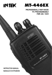
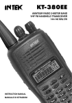
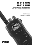
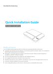
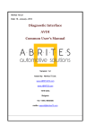
KT-380EE
DX-174S 2-WAY RADIO VHF FM
PROFESSIONAL TRANSCEIVER
136-175 MHz 5W
INSTRUCTION MANUAL
MANUALE DI ISTRUZIONI
Declaration of Conformity
EC Certificate of Conformity
(to EC Directive 99/5-89/336-93/68-73/23)
DECLARATION OF CONFORMITY
With the present declaration, we certify that the following products :
INTEK DX-174S
comply with all the technical regulations applicable to the above mentioned products
in accordance with the EC Directives 73/23/EEC, 89/336/EEC and 99/5/EC.
Type of product :
Details of applied standards :
PMR VHF transceiver
EN 300 086 -1/-2, EN 301 489-1-5
EN 60065
Manufacturer :
INTEK S.R.L.
Via G. Marconi, 16
20090 Segrate, Italy
Tel. 39-02-26950451 / Fax. 39-02-26952185
E-mail : [email protected]
Notified Body :
EMCCert Dr. Rasek
Boelwiese 5, 91320 Ebermannstadt
Germany
Identification Number : 0678
Contact Reference :
Armando Zanni
Tel. 39-02-26950451 / Fax. 39-02-26952185
E-mail : [email protected]
Segrate, 29/03/2007
dr. Vittorio Zanetti
(General Manager)
NOTICE !
It is recommended to carefully read this owner’s manual before using the product. This will also help the user to
prevent using the radio in violation of the regulations valid in the country where the product is used, as well as to
avoid any possible interferences with other services.
0678
RoHS
2002/95/EC
Index . . . . . . . . . . . . . . . . . . . . . . . . . . . . . . . . . . . . . . . . . . . . . . . . . . . . . . . . . . . . . . . . . . . 1
Notice . . . . . . . . . . . . . . . . . . . . . . . . . . . . . . . . . . . . . . . . . . . . . . . . . . . . . . . . . . . . . . . . . . . 1
General information . . . . . . . . . . . . . . . . . . . . . . . . . . . . . . . . . . . . . . . . . . . . . . . . . . . . . . . 2
Unpacking and checking parts . . . . . . . . . . . . . . . . . . . . . . . . . . . . . . . . . . . . . . . . . . . . . . 3
Supplied accessories . . . . . . . . . . . . . . . . . . . . . . . . . . . . . . . . . . . . . . . . . . . . . . . . . . . . . . 3
Preliminary Steps . . . . . . . . . . . . . . . . . . . . . . . . . . . . . . . . . . . . . . . . . . . . . . . . . . . . . . . 4-6
Getting acquainted with the product . . . . . . . . . . . . . . . . . . . . . . . . . . . . . . . . . . . . . . . 7-10
Getting started . . . . . . . . . . . . . . . . . . . . . . . . . . . . . . . . . . . . . . . . . . . . . . . . . . . . . . . . . . 10
Menu Operation . . . . . . . . . . . . . . . . . . . . . . . . . . . . . . . . . . . . . . . . . . . . . . . . . . . . . . . 11-13
Menu Shortcut Keys . . . . . . . . . . . . . . . . . . . . . . . . . . . . . . . . . . . . . . . . . . . . . . . . . . . . . . 13
Self Programming Mode . . . . . . . . . . . . . . . . . . . . . . . . . . . . . . . . . . . . . . . . . . . . . . . . 14-17
Specifications . . . . . . . . . . . . . . . . . . . . . . . . . . . . . . . . . . . . . . . . . . . . . . . . . . . . . . . . . . . 18
Optional accessories . . . . . . . . . . . . . . . . . . . . . . . . . . . . . . . . . . . . . . . . . . . . . . . . . . . . . 18
Notes . . . . . . . . . . . . . . . . . . . . . . . . . . . . . . . . . . . . . . . . . . . . . . . . . . . . . . . . . . . . . . . 40-41
NOTICE !
This transceiver has been factory programmed, in order to use the product immediately after
purchase. The programming includes the activation of channels/frequencies in the VHF FM
PMR Band, according to the technical rules in force for the use of this band.
NOTICE !
This transceiver is programmable via PC, using the dedicated software and the PC interface
cable (optional items). Any programming or modification of the original default setting must be
made by a specialised technician or by an authorised service centre. Some functions of this
transceiver might be programmed in violation of the technical rules in force for the use of the
VHF FM band. It is the user’s responsibility to check that any modification to the programming
will be done in compliance with the current regulations. Any modification to the product,
alteration of the internal circuit, of the external structure of the radio or any programming in
violation of the current regulations will automatically void the product certification and your right
to use the product. INTEK S.R.L. declines any responsibility concerning any modification of the
product, made by the user or by a third party, after delivery of the product.
-1-
English
Index - Notice
General Information
English
Thank you !
Thank you for choosing INTEK for your PMR radio applications. This user friendly transceiver will
provide you with clear and reliable communications and will keep your professional activities at peak
efficiency. This transceiver incorporates the latest and most advanced technology, so you will be
pleased with its quality and its technical features.
Important notice !
The use of VHF FM transceivers is subject to the regulations applied in the country where the product
has to be used. As regulations are usually subject to possible modifications, please check the current
regulations in your country with your dealer or local supplier. INTEK does not take any responsibility for
illegal use and operation of this product not in accordance with the regulation of the country where the
product is used.
Safety notice
The user must know and understand the common risks related to the use of transceivers. Do not use
the transceiver in environments at risk of explosion (where there are gas, dusts, smokes, etc.). Do not
use the transceiver in service areas or fuel stations, on board aircrafts, etc.
Cautions
Please observe the following precautions, in order to avoid causing fire, personal injuries or damage to
the radio:
It is suggested that each transmitted message lasts a few minutes only, since very long
transmissions at the maximum transmitter RF output power may overheat the transmitter.
Do not alter or modify in any way your transceiver.
Do not expose the transceiver for a long time to direct sunlight and do not place it close to
heat sources.
Do not expose the transceiver to excessively dusty or damp places, do not place it on
unstable surfaces.
In case of anomalous smell or smoke that leaks out from the transceiver, turn it off immediately
and remove the battery pack. Please contact an authorised service center.
Please do not dispose off used battery with common garbage. Please use the dedicated
disposal containers.
-2-
Unpacking and checking parts
Carefully unpack the product. Please identify all the parts listed below, before wasting the packaging. If
any part is missing or if the packaging shows any damage, please contact your dealer immediately.
Supplied accessories
Rubber flexible antenna with SMA connector
7.2V 1200mAh Li-Ion Rechargeable Battery Pack
Electronic Quick Desk Charger
Belt Clip
Speaker-microphone Jack Cover
User Manual
Rubber flexible antenna
with SMA connector
Quick Desk Charger
Li-Ion Battery Pack
SP
C
MI
Belt Clip
Speaker-microphone
Jack Cover
-3-
User Manual
English
Unpacking and Checking Parts - Supplied Accessories
Preliminary Steps
English
Battery charging
Connect the 230VAC adaptor charger to the desk type battery charger
and to a 230VAC outlet. The Red Led will flash to confirm that the charger
is powered.
Insert the empty battery or the transceiver with the battery pack in the
battery charger. Please make sure that the charging contacts of the radio
are connected with the charging contacts of the charger cradle. The Red
Led will light then the device is ready to begin the charging process. The
charging time depends on the battery condition and capacity). When the
charging process has finished, the Red Led lights off and the Green Led
will light. Remove the battery pack or the transceiver from the battery
charger and disconnect it from the AC outlet.
Warning !
The battery is supplied empty and it has to be fully recharged before use.
Some complete cycles of charge/discharge will be necessary in order for the battery to reach a
peak efficiency level.
Please do not charge the battery again when it has just been charged. Otherwise, you may
damage the battery or reduce its life.
The battery charger does not switch OFF automatically when charging is complete, therefore
please remove battery or radio from the charger cradle and disconnect it from the AC outlet.
Do not recharge battery for more than 8 hours, in order to avoid battery overheating.
To install the battery
Please align the two battery slots with the fit runner on the lower side of
the transceiver.
Press the battery downward untill the locker placed on the rear side of the
radio hooks and fastens the battery.
-4-
English
Preliminary Steps
To remove the battery
To remove the battery, press the battery locker placed on the rear side of
the radio and slide the battery away from the radio.
Warning !
Please do not waste used batteries into the environment and do not trash them with the common
garbage. Please use the dedicated case for the collection of used up batteries at your supplier.
Do not attempt to open or remove the battery casing.
Do not short the battery terminals or throw the used batteries into fire.
Installing the antenna
Connect the antenna to the antenna connector located on the top panel of
the radio. Gently turn the antenna clockwise until locked.
Warning : Do not touch the antenna and do not move it close to a
microphone cable during transmission, as this might cause malfunction
and damage to the radio.
To install / to remove the belt clip
If necessary, attach the belt clip to the tranceiver, making it slide along the
fit runner placed on the rear side of the battery untill the lock will hook. To
remove the belt clip press the lock and slide the belt clip away from
the battery.
-5-
Preliminary Steps
English
Install the external earset-microphone jack rubber cover.
If an external earset-microphone is not used, please install the earsetmicrophone jack rubber cover.
Install the earset-microphone jack rubber cover, by matching the three
rubber tabs with the holes on the radio, as showed on the drawing.
If the earset-microphone jack rubber cover is removed, radio will not be
splash proof.
To install the external microphone (optional)
To install the external microphone, remove the protection cover of the
external microphone/speaker jack. This cover ensures the watertight
integrity of the transceiver (spray-guard) that will not be ensured after its
removing. Insert the connector of the external microphone into the
right jack.
In order to avoid mulfunction or damage to the transceiver, use only
original microphones. Using non original accessories will authomatically
void the warranty.
Warning !
If an external earset-microphone is used, radio will not be splash proof.
-6-
English
Getting Acquainted with the Product
GETTING ACQUAINTED WITH THE PRODUCT
2
1
3
13
12
14
17
11
10
15
4
16
5
9
6
8
18
7
1.
Antenna
Rubber flexible antenna with SMA connector.
2.
Rotary Switch
Frequency, channel and functions selector.
3.
Power ON switch and volume control
Switch on the transceiver turning the knob clockwise or counterclockwise to switch it off.
To increase the volume, turn the knob clockwise or counterclockwise to decrease it.
4.
LCD Display
Backlighted Dot Matrix LCD Display, provides clear reading and full information on every function
and status of the radio
5.
Menu Key
It scrolls and selects the menu functions.
6.
EXIT Key
Exits any status to stand-by status quickly.
7.
Keypad
Numeric Keypad.
8.
C (Clean) Key
Function key to quickly clean up or exit several functions of the radio.
-7-
Getting Acquainted with the Product
English
9.
FUN Key
Function key to quickly access several functions of the radio.
10.
UP/DOWN Keys
Channels and menu operation selection keys.
11.
Microphone
Built-in microphone.
12.
Speaker
Built-in speaker.
13.
RX/TX LED Indicator
The LED indicator will light in green colour when the radio is receiving a signal and in red colour
during transmission.
14.
PTT key (Push-To-Talk)
To transmit, press and keep pressed the PTT key (14), then speak into the microphone with your
normal voice. To receive release the PTT key (14).
15.
LAMP Key
Rubber key to switch ON and OFF the LCD and keypad backlight function.
16.
MONITOR Key
Press this key to open the Squelch and release it to close the Squelch.
17.
External earset-microphone jack rubber cover
This cover protects the external earset-microphone jack and makes the radio splash proof.
18.
Desktop Charger Contacts
-8-
English
Getting Acquainted with the Product
LCD DISPLAY
A
B
C
D
E
F
G
H
U
I
75
5
25
T
L
M
S
R
Q
P
O
N
A.
Signal Digital Bar Meter
Indicates the received signal strenght in the receive mode.
B.
CT Indication
The CT indication is lighted when the CTCSS function is enabled.
C.
T Indication
Not available on this model.
D.
DCS Indication
The DCS indication is lighted when the DCS function is enabled.
E.
+ - Indication
Not available on this model.
F.
- Indication
Not available on this model.
G.
R Icon
The R icon is lighted when the Reverse function is enabled.
H.
Battery Level Indicator
It shows the current battery level condition.
I.
CTCSS / DCS Code Number
It shows the CTCSS and DTS Codes setting.
L.
Stop Scanning Icon
The channels scanning indicator is lighed when the scanning stops.
M.
MONITOR Icon
This icon is lighted when the Monitor key is pressed.
N.
Keypad Lock Icon
The Lock icon is lighted when the keypad lock function has been enabled.
-9-
Getting Acquainted with the Product - Getting Started
English
O.
VOX Indication
The VOX icon is lighted when the VOX function has been enabled.
P.
Frequency Reading (25-5-75).
It shows the KHz decimal figures of the frequency.
Q.
RF Digital Meter
It indicates the transmitter RF output power.
R.
Dot Matrix Indication
It provides full information on channel, frequency and all enabled functions.
S.
H Icon
The H icon is lighted when the transmitter is in HIGH POWER mode.
T.
S Icon
The S icon is lighted when the automatic channel/frequency scan function has been enable.
The S icon will flash if a signal is detected on a channel.
U.
F Icon
Not available on this model.
GETTING STARTED
Power ON
Switch on the transceiver turning the Power/Volume knob (3) clockwise until you hear a click, the
transceiver now is in stand-by mode.
Volume adjustment
To adjust the volume, turn the volume knob (3) while using the MONITOR (16) key to listen to the
background noise of the channels.
Channel/frequency selection
Select the desired channels, using the UP/DOWN (10) keys or the channels selector (2).
Transmission
In order to transmit, press the PTT (14) key and speak with your normal voice, keeping the microphone
at about 4 cm from your mouth. The LED indicator (13) will light in red color. Release the PTT (14) key
at the end of transmission.
Receiving
Release the PTT (14) key and properly adjusting volume, you will be able to receive the incoming signals.
When receiving a signal, the LED indicator (13) will light in green colour.
- 10 -
MENU OPERATION
In stand-by status, press FUN (9) key to enter the menu.
Press the UP/DOWN (10) keys to choose menu items.
1.
Channel Mode / Frequency Mode
CHANNEL MODE
Press the UP/DOWN (10) keys or use the rotary switch (2) to choose desired channel.
SCAN ---> T->R (reverse frequency) ---> FREQ (Non available) ---> KEYBO (choose
keyboard lock mode) ---> LED (indicator setup) ---> BEEP (warning sound switch setup) ---> POW (RF
output power HI/LOW) ---> SQL (voice level setup) ---> TOT (emission timing setup) ---> VOX (VOX
sensitivity setup) ---> STEP (channel spacing setup).
MODE
SCAN ---> CT/DCS ---> CHANL (switch to channel mode) ---> KEYBO (choose keyboard lock mode) --->
LED (indicator setup) ---> BEEP (warning sound switch setup) ---> POW (RF output power HI/LOW) --->
SQL (voice level setup) ---> TOT (emission timing setup) ---> VOX (VOX sensitivity setup) --->
STEP (channel spacing setup).
2.
Key Function in the Menu Mode
Function Key (9) : enter the menu set-up status
C Key (8) : exits the upper menu or quit menu set-up status
UP/DOWN Keys (10) : choose items
Menu/Confirmation Key (5) : confirm item choice or parameter
EXIT Key (6) : exits any status to stand-by status quickly.
SCAN : scanning
In the stand-by status, press the FUN (9) key to display scanning indicator, and when the LCD Display
shows SCAN ?, press the MENU/CONFIRMATION (5) key to start scanning. If signals exist in one
channel/frequency, the channel/frequency will be displayed. Then press the MENU/CONFIRMATION (5)
key, the Two-Way Radio will stop scanning and remain at the current channel/frequency or else, it will
start scanning for the next channel/frequency after 2 seconds.
T->R (reverse frequency)
In the channel mode, when dual frequency is used to start reverse frequency function, the receiving
frequency and emission frequency will interchange. In the CHANNEL MODE press the FUN (9) key then
press the UP/DOWN (10) keys. When the LCD display shows T->R ?, press the
MENU/CONFIRMATION (5) key to confirm.
- 11 -
English
Menu Operation
Menu Operation
English
CT/DCS (CTCSS / DCS selection)
In the stand-by status, press the FUN (9) key to enter menu page, then press the UP/DOWN (10) keys to
confirm (you will see CT/DCS). Then press the MENU (5) key to enter. Press the UP/DOWN (10) keys to
choose CTCSS or DCS. Press the MENU (5) key to enter the chosen item. Press the UP/DOWN (10)
keys to set up CTCSS or DCS code. When DCS is chosen, press the FUN (9) key to choose forward or
reverse direction, and press the MENU/CONFIRMATION (5) key to complete set-up.
CHANL : switch from frequency mode to channel mode
In the stand-by status, press the FUN (9) key and then numeric key 3 to switch to channel mode.
Alternatively, press the FUN (9) key to find. When the display shows CHANL ?, press the UP/DOWN
(10) keys to switch. (confined to frequency mode only)
KEYBO : Keyboard lock setup
In the stand-by status, press the FUN (9) key and then the UP/DOWN (10) keys to find, and when the
display shows KEYBO?, press the MENU/CONFIRMATION (5) key to enter. You will see two options
available, AUTO and MANUAL.
AUTO: automatic locking
When this option is chosen, the keyboard will be locked automatically when no operation is performed.
MANUAL: manual locking
When this option is chosen, the keyboard cannot be locked automatically.
LED : light setup
In the stand-by status, press the FUN (9) key and then the UP/DOWN (10) keys, and when the display
shows LED ?, press the MENU/CONFIRMATION (5) key to enter. You will see three options available:
AUTO, MANUAL and ON. Press the MENU/CONFIRMATION (5) key to select the desired item.
AUTO: When this option is chosen, the display light will be turned on once you press the key.
MANUAL: When this option is chosen, the display light will not be turned on automatically.
You have to operate the side key manually to use light.
ON: When this option is chosen, the display light will be turned on all the time. The light will be on
without any operation.
BEEP : warning sound setup
In the stand-by status, press the FUN (9) key and then the UP/DOWN (10) keys, and when the display
shows BEEP ?, press the MENU (5) key to enter. Press the UP/DOWN (10) keys, and you can see ON
and OFF in turns. You can choose sound ON or OFF by pressing the MENU/CONFIRMATION (5) key.
POW : RF output power setup
In the stand-by status, press the FUN (9) key and then the UP/DOWN (10) keys, and when the display
shows POW ?, press the MENU (5) key to enter. Press the UP/DOWN (10) keys, and you can see H
and L in turns. You can choose high / low power by pressing the MENU/CONFIRMATION (5) key.
- 12 -
SQL : Squelch level setup
In the stand-by status, press the FUN (9) key and then UP/DOWN (10) keys, and when the display shows
SQL ?, press the MENU/CONFIRMATION (5) key to enter. Press the UP/DOWN (10) keys to choose the
desired squelch level and confirm the selection by pressing the MENU/CONFIRMATION (5) key.
TOT : Emission Timing Setup
In the stand-by status, press the FUN (9) key and then the UP/DOWN (10) keys, and when the display
shows TOT ?, press the MENU/CONFIRMATION (5) key to enter. Press the UP/DOWN (10) keys to set
up emitting time limit. The time unit is in seconds. Press the MENU/CONFIRMATION (5) key to confirm
the selection.
VOX : VOX Level Setup
In the stand-by status, press the FUN (9) key and then the UP/DOWN (10) keys, and when the display
shows VOX ?, press the MENU/CONFIRMATION (5) key to enter. Press the UP/DOWN (10) keys to
set up the desired VOX level and press the MENU/CONFIRMATION (5) key to confirm the selection.
STEP : Channel Spacing Setup
In the stand-by status, press the FUN (9) key to enter the menu mode, then press the UP/DOWN (10)
keys and when the LCD shows STEP ?, press the MENU/CONFIRMATION (5) key to enter.
Press the UP/DOWN (10) keys to select the desired channel spacing and press the
MENU/CONFIRMATION (5) key to confirm the selection.
MENU SHORTCUT KEYS
Press the FUN (9) key, then press the numeric key to enter appropriate items. This shortcut function is
same as the items of menu, but they more easy to operate the Two Way Radio.
FUN + 1
FUN + 2
FUN + 3
FUN + 4
FUN + 5
FUN + 6
FUN + 7
FUN + 8
FUN + 9
FUN + 0
Enter the channel/frequency scanning.
Switches ON/OFF the Reverse Frequency function and exits stand-by status
Not available
The way of keyboard locking (auto/manual) set-up.
LED light set-up.
Warning sound setup.
High/Low RF output power setup.
Squelch level setup.
Emission timing setup.
Swithes on the VOX function and VOX level setup.
FUN + *
FUN
Keyboard Lock/Unlock
- 13 -
English
Menu Operation - Menu Shortcut Keys
Specifications - Optional Accessories
English
SPECIFICATIONS
General
Frequency
Channels
Channel spacing
DC input voltage
Operating temperature
Dimensions
Weight
136.000 - 174.9875 MHz
80
12.5, 25 KHz
7.2 VDC
-20/+55°
mm 58 x 120 x 35
235 gr. (with battery and antenna)
Receiver
Sensitivity (12dB Sinad)
Selectivity
Intermodulation
Audio output
0.16 µV
65dB
60dB
500mW
Transmitter
RF output power
Modulation
Spurious & Harmonics
Maximum deviation
Frequency Stability
5W / 1W
FM
in compliance with the R&TTE regulations
≤ ±2.5KHz
±2.5ppm
OPTIONAL ACCESSORIES
-
KME-315
KME-614
KME-801
KME-100A
KME-200A
KME-H115
KST-301
CDDX-174S
External Earset-Microphone with tie clip
External Earset-Microphone with adjustable ear hook
External Earset-Microphone for security and bodyguard
External Earset-Microphone with tie clip
External Earset-Microphone with flexible boom mic and tie clip
External Speaker-Microphone (light duty)
External Speaker-Microphone (heavy duty)
Programming Kit (PC interface cable and software CD)
User Information
in accordance with art. 13 of the Legislative Decree of 25th July 2005, no. 15 ”Implementation of Directives 2002/95/EC, 2002/96/EC and
2003/108/EC, relative to reduction of the use of hazardous substances in electrical and electronic equipment, in addition to waste disposal”.
The crossed bin symbol shown on the equipment indicates that at the end of its working life the product must be collected
separately from other waste.
The user must therefore take the above equipment to the appropriate differentiated collection centres for electronic and
electro technical waste, or return it to the dealer when purchasing a new appliance of equivalent type, in a ratio of one to one.
Appropriate differentiated waste collection for subsequent recycling, treatment and environment-friendly disposal of the
discarded equipment helps to prevent possible negative environmental and health effects and encourages recycling of the
component materials of the equipment.
Illegal disposal of the product by the user will be punished by application of the administrative fines provided for by the legislative
decree no. 22/1997 (article 50 and following of the legislative decree no. 22/1997).
- 18 -