1
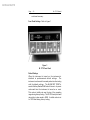
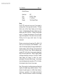
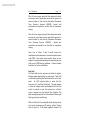
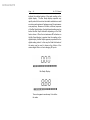
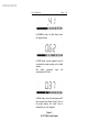
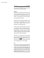
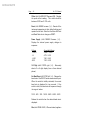
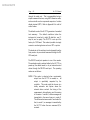
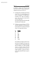
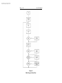
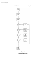
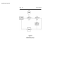
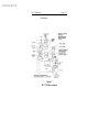
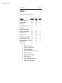
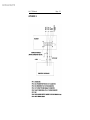
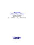
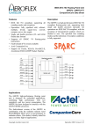
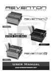
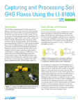
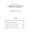
Archived 4/2/10
HI-1710
Microwave Measurement System
User's Manual
Copyright
Manual #600032
© 2000 by Holaday Industries, Inc.
2/00
$25.00
Archived 4/2/10
Revision Record
Manual #600032
HI-1710 Microwave Measurement System
Revision
G
Description
Reformatted
Date
2/00
Archived 4/2/10
TABLE OF CONTENTS
1.0 DESCRIPTION . . . . . . . . . . . . . . . . . . . . . . . 1
Introduction . . . . . . . . . . . . . . . . . . . . . . . . 1
2.0 HIn1710 SPECIFICATIONS . . . . . . . . . . . . . 3
Error Analysis . . . . . . . . . . . . . . . . . . . . . . . 4
Calibration . . . . . . . . . . . . . . . . . . . . . . . . . 5
3.0 ACCEPTANCE . . . . . . . . . . . . . . . . . . . . . . 5
Introduction . . . . . . . . . . . . . . . . . . . . . . . . 5
Unpacking and Acceptance . . . . . . . . . . . . . 5
4.0 OPERATIONS . . . . . . . . . . . . . . . . . . .
Start Up . . . . . . . . . . . . . . . . . . . . . . .
Front Panel Settings . . . . . . . . . . . . . .
Default Settings . . . . . . . . . . . . . . . . .
Range . . . . . . . . . . . . . . . . . . . . . . . .
Filter . . . . . . . . . . . . . . . . . . . . . . . . .
Peak Hold . . . . . . . . . . . . . . . . . . . . .
Alarm Set . . . . . . . . . . . . . . . . . . . . .
Zero . . . . . . . . . . . . . . . . . . . . . . . . .
Over Range . . . . . . . . . . . . . . . . . . . .
Shift Functions . . . . . . . . . . . . . . . . . .
Bias . . . . . . . . . . . . . . . . . . . . . .
Offset . . . . . . . . . . . . . . . . . . . .
Reset . . . . . . . . . . . . . . . . . . . . .
Power Supply . . . . . . . . . . . . . . .
3/4 Digit . . . . . . . . . . . . . . . . . . .
Set Baud Rate . . . . . . . . . . . . . . .
Stim . . . . . . . . . . . . . . . . . . . . .
Using the HI-1710 . . . . . . . . . . . . . . . .
Analog Outout . . . . . . . . . . . . . . . . . .
Digital (RS-232) Input/Output . . . . . . . .
Error Messages . . . . . . . . . . . . . . . . . .
Connection and Operation of the RS-232
Serial Data Port . . . . . . . . . . . . . . . . . .
.
.
.
.
.
.
.
.
.
.
.
.
.
.
.
.
.
.
.
.
.
.
.
.
.
.
.
.
.
.
.
.
.
.
.
.
.
.
.
.
.
.
.
.
.
.
.
.
.
.
.
.
.
.
.
.
.
.
.
.
.
.
.
.
.
.
. 9
. 9
10
10
11
12
13
16
16
17
17
17
18
18
18
18
18
18
19
20
21
26
. . . 27
Archived 4/2/10
5.0 THEORY OF OPERATION . . . . . . . . . . . . . . 35
6.0 TEST AND TROUBLESHOOTING
Error Codes . . . . . . . . . . . . . .
Checks and Adjustments . . . . .
Chip Revisions . . . . . . . . . . . .
Replacement Parts . . . . . . . . . .
.
.
.
.
.
.
.
.
.
.
.
.
.
.
.
.
.
.
.
.
.
.
.
.
.
.
.
.
.
.
.
.
.
.
.
.
.
.
.
.
.
.
.
.
.
41
41
43
45
46
APPENDIX A
RS-232 Command Set . . . . . . . . . . . . . . . . 49
APPENDIX B
RS-232 Connections . . . . . . . . . . . . . . . . . 51
APPENDIX C
Zero Receptacle . . . . . . . . . . . . . . . . . . . . 53
Archived 4/2/10
Limited Warranty
Holaday Industries, Inc. warrants each model HIn1710
Microwave Measurement System to be free from defects in
material and workmanship for a period of one year from the date
of shipment to the purchaser. This warranty extends to the
original purchaser only, and does not apply to the batteries or to
any products or parts subject to misuse, neglect, accident,
unauthorized service or abnormal conditions of operation.
In the event an instrument covered by this warranty fails,
Holaday Industries, Inc. will, without charge, repair and
recalibrate the instrument if returned to their factory within one
year of the original purchase-provided that Holaday Industries'
examination discloses, to its satisfaction, that the product is
defective. Holaday Industries, Inc., may, at its option, replace
the product in lieu of repair. If the defect was caused by misuse,
neglect, accident, unauthorized service or abnormal conditions of
operation, repairs will be billed at a nominal cost. In such cases,
an estimate will be provided before work is started, if requested
by the purchaser.
For warranty service, contact Holaday Industries, Inc. Provide
the serial number of the instrument and complete details
regarding the failure mode. You will then be given either service
information or shipping instructions. Return the instrument to
the factory, transportation prepaid. Repairs will be made at the
factory and the instrument will be returned to you, transportation
prepaid. Holaday Industries, Inc., assumes no responsibility for
loss of, or damage to, products in transit.
Warning!
EXTREME CAUTION IS ADVISED WHEN WORKING IN
ENVIRONMENTS WHERE HIGH-INTENSITY ELECTROMAGNETIC
FIELDS MAY EXIST AND WHERE CONTACT WITH HIGH VOLTAGE
OR HIGH CURRENT CIRCUITS OR APPARATUS IS POSSIBLE.
ACCIDENTAL CONTACT WITH OBJECTS OR CIRCUITS OPERATING
AT HIGH VOLTAGES OR HIGH CURRENTS CAN BE LETHAL!
HOLADAY INDUSTRIES, INC. ASSUMES NO LIABILITY FOR ANY
DAMAGES OR PERSONAL INJURY WHICH MAY RESULT FROM
Archived 4/2/10
HIn1710 Manual
Page — 1
1.0 DESCRIPTION
Introduction
The HI-1710 Microwave Measurement System is
designed to operate from standard 50/60 Hz. 115 or
230 VAC power. The circuitry is powered by a regulated
supply with normal industrial transient protection devices.
The push button power switch located on the front panel
of the instrument turns the instrument on and off. The
instrument provides four different time response
characteristics which allows standard hand scan
measurements according to CDRH Performance Standard
for Microwave Ovens, CFR 1030.10 as well as the
potential for faster scanning similar to that of automated
scanning systems. The instrument is calibrated for
measurement in the 2450 MHz ISM band only. The
instrument is shielded with the necessary isolating and
attenuating devices to provide immunity to stray leakage
of microwave energy.
The diode detection array of eight hot carrier diodes is
housed in the large end of the plastic probe assembly.
This antenna array has the unique feature of being able to
sum microwave electric fields of any plane perpendicular
to the axis of the probe. The antenna lobe is also very
broad, making the instrument easy to use when
measuring leakage around an oven door. The cone
spacer is designed to provide 5 cm spacing (as required
by the CDRH performance standard) from the tip of the
probe cone to the center of the array. The shape of the
cone provides minimum perturbation of the electric field
impinging on the diode array. The probe is attached
permanently to the pre-amplifier assembly by a 9 foot
shielded cable. Each detection probe and amplifier
assembly is calibrated as a unit and can be used
interchangeable with any HI-1710 Readout. The digital
Archived 4/2/10
Page — 2
HIn1710 Manual
indicator reads with two or three decimal place resolution
from zero to 10 mW/cm2. Temporary over-exposure to
microwave fields up to 2000 mW/cm2 will not cause
probe burn-out or damage the instrument or its
calibration.
Four ranges with full scale indications of 1, 2, 5, and 10
mW/cm2 or auto-range can be selected from the front
panel. With the instrument set to auto-range, the
microprocessor controller will select the best range for
each measuring condition.
Selecting the range,
determines the full scale setting of the bar graph display
located below the digital readout to give a continuous
analog indication of the leakage level being measured.
The audio alarm circuit can be set to any level up to 10
mW/cm2. Whenever the level of the microwave leakage
exceeds the preselected value, the audio alarm will
sound, alerting the operator that the chosen level has
been exceeded.
Archived 4/2/10
HIn1710 Manual
Page — 3
2.0
HIn1710 SPECIFICATIONS
1.
Calibrated at 2450 MHz. for use in the ISM band.
2.
Four ranges: 0-1, 0-2, 0-5, 0-10 mW/cm2.
3.
Response Characteristics (0 to 90% of final value
for step input):
F1 - 1.2 seconds (2 stage Butterworth filter, Fc =
0.5 Hz.)
F2 - Less than 0.5 second (2 stage Butterworth
filter, Fc = 0.5 Hz.)
F3 - Four Pole Butterworth filter, Fc = 0.45 Hz.
F4 - Four Pole Butterworth filter, Fc = 0.90 Hz.
4.
Maximum Power Density 2.0 Watts/cm2 (2000
mW/cm2)
5.
Power: 115/230
selectable)
6.
Operating Temperature: 15/ - 40/ Celsius
7.
Dimensions:
11
(280x204x165mm)
8.
Probe Length: 12 inches (305 mm)
Cable Length: 9 feet (2.74 meters)
9.
Shipping weight: 15 pounds (6.8 KG)
VAC
x
50-60
8
Hz.
x
6.5
(switch
high
Archived 4/2/10
Page — 4
Error Analysis
HIn1710 Manual
1.0 mW/cm2
Absolute Calibration
+0.30 dB
Precision
±0.13
Linearity and AM response
±0.15
Frequency Response1
±0.04
Near field response
±0.29
Polarization1
±0.21
Pattern
+0/-0.11
Temperature
+0.46/-0.15
Supply Voltage
±0.01
RFI1
±0.01
Overload
±0.01
Drift1
±0.04
________________
-1.098/+1.498
dB
note 1: values are combined in an RMS manner
Archived 4/2/10
HIn1710 Manual
Page — 5
Calibration
Each Probe/preamp assembly is calibrated by placing the
probe in a known 2450 MHz field. Calibration is
performed at a standard temperature of 75 degrees
Fahrenheit in an anechoic chamber, utilizing a slot
radiator. A CW field is generated using a crystal
controlled solid state source. The power monitoring
system is the HI-2795 Calibration Comparison System.
The calibration field level is established using a reference
survey meter with CDRH calibration correction factors.
All ranges are calibrated at mid-scale.
Archived 4/2/10
Page — 6
HIn1710 Manual
Archived 4/2/10
HIn1710 Manual
3.0
Page — 7
ACCEPTANCE
Introduction
This section contains information on unpacking and
acceptance of the HIn1710.
Unpacking and Acceptance
Step 1. Upon delivery of your order, inspect the
shipping container(s) for evidence of damage.
Record any damage on the delivery receipt
before signing. In case of concealed damage or
loss, retain the packing materials for inspection
by the carrier.
Step 2.
Remove the instrument from its shipping
containers. Save the boxes and any protective
packing materials for future use.
Step 3.
Check all materials against the packing list to
verify that the equipment received matches that
which was ordered.
If you find any
discrepancies, note them and call Holaday
Customer Service (952-934-4920) for further
instructions.
Be sure that you are satisfied with the contents of your
order and the condition of your equipment before
installing the instrument.
Archived 4/2/10
Page — 8
HIn1710 Manual
Archived 4/2/10
HIn1710 Manual
Page — 9
4.0 OPERATION
Start Up
(The instrument should not be used without spacer cone
in place.)
1.
Insert the probe/preamp tube into the receptacle in
the HI-1710 front panel with the power OFF. The
preamp tube must be oriented with the locating
screw facing up. Be sure that the pins are securely
mated with the socket in the instrument front panel.
Note that the preamp tube is inserted into the probe
opening such that the indicator arrow on the brass
tube is aligned with the edge of the grounding ring.
2.
Check that the input voltage select switch (located
on the rear panel of the unit) is set to the proper
voltage level. Connect theinstrumentto the AC
supply line.
3.
Power is applied to the system by depressing the
power switch located in the upper right corner of
the instrument front panel. When the power is first
turned on, the microprocessor performs a series of
self-tests on the measuring circuitry of the meter.
Refer to section 6.0 (Test and Trouble Shooting) for
more information.
When the initial tests are
complete, the system is in its default mode and
ready for operation.
4.
Check the spacer cone for damage, discoloration, or
contamination. Accuracy will be affected by cone
wear or damage or by contamination by metallic
particles which may become imbedded in the cone.
Replace the cone if necessary. Replace the cone
only with a Holaday Industries replacement cone for
Archived 4/2/10
HIn1710 Manual
Page — 10
continued accuracy.
Front Panel Settings
Refer to figure 1
Figure 1
HI-1710 Front Panel
Default Settings
When the instrument is turned on, the instrument is
initialized to pre-determined default settings.
The
instrument can be used for normal production line testing
with the default settings. The ALARM SET POINT is
saved in Battery Backed RAM and will return to its preset
value each time the instrument is turned on or reset.
This value is initially set near the top of the operating
range during factory testing. The RS-232 serial port baud
rate setting is also saved in RAM. Its initial value is set
to 1200 baud during factory testing.
Archived 4/2/10
HIn1710 Manual
Page — 11
Default Settings:
Peak Hold
Filter
Range
Display
-
OFF
FILTER 1 (Slow)
0-1 mW/cm²
Two Decimal Places
Range
The HI-1710 can be set to any one of four ranges by
pressing either of the range select switches. The range
affects only the Bar Graph Display and the Analog
Output; the digital display will always indicate any value
between zero and 10 mW/cm2. Pressing the right range
switch (>) changes the instrument to the next higher
range; each depression of the switch moves one range.
Pressing the left range switch moves the range
downward.
Moving one step beyond range four (10 mW/cm2 full
scale), sets the instrument to AUTO-RANGE. In this
mode, the instrument adjusts the range automatically for
the best reading. With no RF input, the instrument will
shift to the 0-1 mW/cm2 scale. When the displayed value
exceeds 95% of full scale, the instrument automatically
selects the next higher scale. While the digital reading
will always indicate any value up to 10 mW/cm2, the Bar
Graph display will change to reflect the correct
percentage of the newly selected range. In auto-range,
when the displayed value drops below 30% of full scale,
the instrument selects the next lower range.
Note: When using the Auto-Range feature and Peak Hold
together, the highest range selected is locked in. This is
because the peak segment on the Bar Graph display is
located as a proportion of the highest auto-selected
range. When the instrument is zeroed, the auto-range
Archived 4/2/10
Page — 12
HIn1710 Manual
will reset to the lowest range (1 mW/cm2).
The range selection switches feature wrap-around
operation which means that when the instrument is in its
lowest range and the left or lower range (<) switch is
pressed, the instrument will move to the auto-range
setting. When the instrument is in auto-range and the
right or increase range switch (>) is pressed, the
instrument will move to the 1 mW/cm2 setting.
Filter
The HI-1710 is internally programmed with four response
times (filters). This digital filtering changes the way the
instrument responds to rapidly changing RF or leakage
levels. Refer to section 5.0 (Theory of Operation). Filters
are selected by pressing the right or left filter select
switches located beneath the filter selection indicating
LEDs on the front panel.
Filter 1 is equivalent to the "SLOW" response mode on
analog meters. This is the default setting and is the
setting used for most hand scanning of microwave ovens.
This setting responds more slowly to rapidly changing RF
or leakage levels and tends to average the response to
peak levels caused by oven mode stirring devices. This
response characteristic is designed to meet the CDRH
requirement that an instrument respond to a step CW
microwave input to 90% of its steady state reading
within a maximum of three seconds while still providing
maximum smoothing of RF peaks.
Filter 2 is equivalent to the "FAST" response mode on
analog meters. The filter selection is used for observing
rapid variations in RF leakage and evaluating the effect of
stirrer modulation on leakage.
Archived 4/2/10
HIn1710 Manual
Page — 13
Filter 3 is a four stage, eight pole filter designed for faster
scanning of ovens having slow mode stirrer speeds in a
manner similar to that used by Automatic Microwave
Oven Scanning Systems (AMOSS). Special test
procedures are required to use this filter for compliance
testing.
Filter 4 is a four stage, eight pole filter designed for faster
scanning of ovens having faster mode stirrer speeds in a
manner similar to that used by Automatic Microwave
Oven Scanning Systems (AMOSS).
Special test
procedures are required to use this filter for compliance
testing.
Note: Use of Filters 3 and 4 would require the
development and submission of a revised compliance plan
with CDRH. Such a plan would need to show an error
analysis of sample data comparing the proposed scan rate
with current CDRH testing guidelines. Contact Holaday
Industries for further information.
Peak Hold
The Peak Hold function captures and holds the highest
leakage reading displayed by the instrument. Peak Hold
is activated by pushing the Peak Hold switch on the front
panel.
An LED indicator lights to show that the
instrument is in the Peak Hold mode. The peak reading
is stored as a digital value and displayed until the Zero
switch is pushed to reset the instrument or until the
probe is inserted into the optional Zero Chamber. The
peak reading displayed is the value obtained following all
filtering and signal conditioning.
While in Peak Hold, the analog Bar Graph display shows
the current instantaneous RF reading, without filtering
(refer to figure 2). A Bar Graph segment remains lit to
Archived 4/2/10
HIn1710 Manual
Page — 14
indicate the relative location of the peak reading on the
digital display. The Bar Graph display responds very
rapidly and will show stirrer/turntable modulation as well
as minima and maxima of leakage around the microwave
oven periphery. Because of the fast, unfiltered, response
of the Bar Graph display, the digital peak reading may lag
behind the Bar Graph indication depending on the filter
factor chosen. When the instantaneous RF indication on
the Bar Graph display is greater than the reading on the
digital display, the Bar Graph segment proportional to the
digital reading is dark. In this way the Peak Hold mode of
the meter can be used to observe the effects of the
various digital filters on fast changing RF inputs.
Bar Graph Display
Two end segments are always lit to define
the scale.
Archived 4/2/10
HIn1710 Manual
Page — 15
In NORMAL mode, the Bar Graph tracks
the digital display.
In PEAK mode, a single segment stays lit
to indicate the peak reading on the digital
display.
Bar
Graph
segments
track
the
instantaneous RF level.
In PEAK mode, when the instantaneous RF
level exceeds the filtered “peak” level on
the digital display, the “peak” level is
indicated by an unlit segment.
Figure 2
HI-1710 Bar Graph Display
Archived 4/2/10
Page — 16
HIn1710 Manual
In the normal (non-PEAK HOLD) mode, the Bar Graph
display follows the filtered display reading.
Alarm Set
The HI-1710 has an audible alarm feature to indicate that
the measured leakage has exceeded a preset level. The
Alarm Set function is controlled by two front panel touch
switches. The upper switch raises the set point and the
lower switch lowers the set point.
Pressing either switch momentarily displays the current
alarm set point on the digital display as well as causing
the Bar Graph to display the alarm set point as a
percentage of the current range setting.
If either switch is pressed continuously, the alarm set
point will begin to increase or decrease depending on the
switch activated. The rate at which the set point
changes increases as the switch continues to be pressed.
To slow the change rate for precise settings, momentarily
release the switch and then activate again.
The alarm is set to the high end of the scale at the
factory. Note that the alarm will sound only when the
displayed RF value exceeds the alarm setting, e.g. if the
alarm is set at 4.99 mW/cm2, the alarm will only sound
when the displayed RF level is 5.00 or greater.
Zero
The zero switch subtracts the current offset reading from
the probe from the currently displayed RF reading. This,
in effect, subtracts a number from itself resulting in zero.
It is important to note there must be no RF present in the
vicinity of the probe when the zero switch is activated.
Doing so will cause an inaccurate zero. The zero will drift
as the instrument's electronic circuitry and diodes warm
Archived 4/2/10
HIn1710 Manual
Page — 17
up to normal operating temperature. There will also be
small variations as the ambient temperature changes
during the day. For these reasons, the zero point of the
instrument must be reset periodically.
In addition, the bias and offset readings are checked
against preset internal limits each time the zero switch is
activated. If the limits are exceeded, an error message is
displayed. Zeroing the instrument in a sufficiently high
RF field or zeroing the instrument with the probe removed
will also cause an error. These tests measure the
performance characteristics of the probe and serve as
failure indicators.
Over Range
If the unfiltered RF signal from the probe exceeds 20
mW/cm2 or the filtered RF signal exceeds 10 mW/cm2,
the over range indicator will turn on. The over range
indication is latched to indicate that a signal has
exceeded the measuring capabilities of the system. The
over range condition is reset when the instrument is rezeroed.
Shift Functions
Several additional performance indicators and settings are
available at the front panel through the use of shifted
touch switches. To indicate a shifted function, press and
hold the zero switch while activating one of the shifted
switches. Note that some shifted switches are not
marked on the front panel.
Bias (shift ALARM SET Increase [v]) - Displays the
probe bias reading. This value should be between
0.300 and 0.4.00 volts.
Archived 4/2/10
Page — 18
HIn1710 Manual
Offset (shift ALARM SET Decrease [w]) - Displays
the probe offset reading. This value should be
between 0.005 and 0.100 volts.
Reset (shift RANGE Increase [>]) - Resets all the
instrument parameters to their default settings and
repeats the self-test. Note that the Alarm Set Point
and Baud Rate do not change on RESET.
Power Supply (shift RANGE Decrease [<]) Displays the internal power supply voltages in
sequence:
Voltage
+4.000
+5
+8.00
-8.00
Acceptable Range
3.995 - 4.005
4.75 - 5.25
7.60 - 8.40
7.92 - 8.08
3/4 Digit (shift FILTER right [>]) - Alternately
selects 3 or 4 digit display (two or three decimal
places).
Set Baud Rate (shift FILTER left [<]) - Changes the
baud rate of the RS-232 serial communication port.
When the switch is initially activated, the current
baud rate is displayed for two seconds. If the
switch is held, the baud rate will sequence through
its range of values:
1200 - 600 - 300 - 19.2K - 9600 - 4800 - 2400
Release the switch when the desired baud rate is
displayed.
Stim (shift PEAK HOLD) - When activated, applies a
Archived 4/2/10
HIn1710 Manual
Page — 19
dc voltage to the input of the RF signal circuitry.
The displayed reading should be between 2.44 and
4.88. Readings outside this range indicate a fault in
the HI-2623 probe/preamp.
Using the HI-1710
Allow the instrument to warm up for at least 10 minutes
for specified accuracy and stability.
Set the operating settings according to the test needs.
For normal tests or a good beginning point, use the
default conditions. Zero the instrument before beginning
the test. With the oven operating with a suitable load,
move the probe across the oven surfaces keeping the
probe axis (handle) perpendicular to the potential leak
area.
Note: Check the spacer cone for damage, discoloration,
or contamination. Accuracy may be affected by cone
wear or damage or by contamination by metallic particles
which may become imbedded in the cone. Replace the
cone if necessary. Replace the cone only with a Holaday
Industries replacement cone for continued accuracy.
Refer to section 6.0 (Test and Troubleshooting) for part
numbers.
Hold the probe by the red handle only to avoid potential
interference and keep other parts of the body and the
probe cord away from the immediate vicinity of the probe
head.
The analog Bar Graph display may be used to determine
areas of highest leakage. In the normal ( non-Peak Hold)
mode the Bar Graph display will track the displayed
digital value and respond to the filtered RF signal. When
the instrument is operated in the Peak Hold mode, the Bar
Archived 4/2/10
Page — 20
HIn1710 Manual
Graph display is not filtered and responds very rapidly to
changes in RF intensity. The Peak Hold mode may be
used, while scanning, to capture the area of highest
leakage while the Bar Graph will continuously display
instantaneous variations in leakage.
Changing the filter selection to F2 will decrease the
response time of the system. This will more effectively
show the effect of rapid variations in RF levels due to
mode stirrers or other modulating devices. In both the F1
and F2 filter positions, the response time meets the
CDRH (US Government) requirement for RF measuring
instrument response times while the F1 response
characteristic provides maximum smoothing of RF
variations.
Note: Do not use filter selection F3 and F4 for US
compliance testing without prior approval of CDRH.
Contact Holaday Industries for further information.
After the test is completed and the RF reading recorded
the instrument should be zeroed by activating the ZERO
switch before the next test. The zero point may
gradually drift over long periods. Re-zero the instrument
before beginning a test.
Analog Output
An analog output is available on the rear panel of the HI1710. This is the BNC receptacle just to the right of the
25 pin RS-232 receptacle. The analog output is a dc
voltage varying from zero to four (0-4) volts proportional
to the full scale range setting of the instrument. For
example, with the instrument on range 2 (0-2 mW/cm2),
a leakage value of 2 mW/cm2 will have an analog signal
of 4 VDC and a 1 mW/cm2 value will have a signal of 2
VDC. On range 4 (0-10 mW/cm2), the four (4) volt
Archived 4/2/10
HIn1710 Manual
Page — 21
analog output signal will indicate 10 mW/cm2.
Figure 3
HI-1710 Rear Panel
Important: The resistance of the external load connected
to the analog output receptacle should not be less than
5000 ohms.
Digital (RS-232) Input/Output
A full, two-way RS-232 serial data port is provided as
standard equipment on the HI-1710. External devices are
connected through the standard 25 pin RS-232
receptacle at the rear of the instrument. These external
devices can monitor and/or control the HI-1710. Refer to
Appendix B for pin designations.
With the serial data port, all functions normally accessed
by the touch switch inputs can be controlled externally
and all data normally displayed can be transmitted
Archived 4/2/10
Page — 22
HIn1710 Manual
through the serial port. This is accomplished using a
simple command structure, using ASCII character codes,
and a controller such as a personal computer of a video
display terminal (VDT). Refer to Appendix A for a list of
control codes.
The default mode of the HI-1710 generates a formatted
test summary.
The default conditions (when the
instrument is turned on) is eight (8) data bits, one (1)
stop bit, and no parity. The HI-1710 is set up at the
factory for 1200 baud. This makes it possible to simply
connect a monitoring device such as a VDT or printer.
The baud rate of the serial port can be changed from the
front panel or by an external command through the RS232 serial port.
The RS-232 serial port operates in one of four modes.
The particular mode is selected either by the HI-1710 on
power-up (the default mode) or by an external control
device through the RS-232 serial port. The operating
modes are as follows:
MODE 0 This mode is selected when no automatic
output from the HI-1710 is needed, ie., all
output is specifically requested by the
controller. This mode might be chosen in a
totally automatic test system where the
external device controls the timing of the
measurement, data gathering, and the zeroing
of the meter. In mode 0, status messages are
transmitted in the same form as in mode 2.
The difference between mode 0 and mode 2 is
that, in mode 0, no message is transmitted by
the HI-1710 when the zero command (Z) is
received.
Archived 4/2/10
HIn1710 Manual
Page — 23
MODE 1 In mode 1, the HI-1710 continually sends the
RF reading through the RS-232 serial port. This
mode transmits data at a high rate and can only
be used at baud rates of 4800 and above. The
instrument sends data at a rate of 45 Hz., the
same rate at which the probe is sampled. The
controlling device must be able to receive a
serially transmitted 4 digit number 45 times a
second. Mode 1 might be used in the
laboratory to investigate the effects of different
filter constants and scan rates. The output
from the HI-1710 in mode 1 is a four digit
ASCII string with the form X.XXX.
MODE 2 Mode 2 is the power - on default mode. In this
mode the HI-1710 sends a preformatted report
through the RS-232 serial port each time the
instrument is zeroed. This format is most useful
when using the Peak Hold mode. With this
configuration, a serial input printer setup to
print adhesive backed labels can be connected
to the RS-232 serial port of the HI-1710. After
scanning an oven, the meter is zeroed. On
zeroing, a ticket is printed with the maximum
leakage observed as well as several system test
parameters. The output is formatted for a
standard 15/16 x 3 inch label. Line feed (LF)
characters are transmitted following the
formatted data to advance one additional label
space with each formatted output. By printing
the report on every other label, the labels can
be removed from the backing more
conveniently.
Archived 4/2/10
HIn1710 Manual
Page — 24
The status message formats for modes 0,1,
and 2 are as follows:
SO: DIGITS = V/AUTO RNG WWW/PEAK
HOLD XXX/YY RNG/PRINT MODE Z
Where V is 3 or 4, WWW is ON or OFF,
XXX is ON or OFF, YY is IN or OUT, Z is
0,1,2
S1: ALARM----X.XX
S2: SCALE----X
S3: FILTER - X / Y STAGES Z.ZZ HZ CUT OFF
Refer to the S3 command in later in this
section (Connection and Operation of the
RS-232 Serial Data Port) for a full
description of the filter messages.
S4: BIAS --- X.XXX
S5: OFFSET --- X.XXX
S6: STIM --- X.XX
S7: 4 VOLTS - X.XXX
5 VOLTS - X.XXX
8 VOLTS - X.XXX
-8 VOLTS - X.XXX
S8: RDNG OK - X.XX
(sends three decimal places [X.XXX] when
in four digit display mode)
Archived 4/2/10
HIn1710 Manual
Page — 25
MODE 3 Mode 3 changes the output format of the
status messages (S0-S8). The transmitted
messages are shortened for easier adaptation to
a computer interface program.
The zero
command does not transmit a formatted report
as in mode 2. In mode 3 the transmitted status
messages end with only a carriage return (CR)
terminator. In modes 0,1, and 2, the messages
end with a carriage return and a line feed
(CR/LF).
The status message format for mode 3 is as
follows:
S0: XXXXX
First digit = 3 or 4 for number
of digits displayed and
transmitted.
Second digit = 0 or 1 for
Auto-Range off or on.
Third digit = 0 or 1 for Peak
Hold off or on.
Fourth digit = 0 or 1 for in
range or over range.
Fifth digit = 0, 1, 2, or 3 for
operating mode.
S1: X.XX
Alarm trigger point (X.XXX
when in four digit mode).
S2: X
Range number 1-4.
S3: XXX.XX
First digit = filter number (14)
Second digit = number of
filter stages.
Digits 3-6 = filter cutoff
Archived 4/2/10
HIn1710 Manual
Page — 26
frequency.
Example:120.50
Filter 1Two stages Cutoff
frequency 0.50 Hz.
S4: X.XXX
Bias voltage.
S5: X.XXX
Offset - milliwatts.
S6: X.XX
Stim test value (X.XXX in four
digit mode).
S7: X.XXX
X.XXX
X.XXX
X.XXX
4 volt power supply level.
5 volt power supply level.
8 volt power supply level.
-8 volt power supply level.
Note: A carriage return (CR) is sent after
each value. A line feed (LF) is not sent.
S8: X.XX
RF reading (X.XXX in four
digit mode).
Error Messages
In any mode, an invalid command will produce an error
message ENTRY ERROR -- PLEASE RETRY. In addition,
the following error messages will be transmitted if, during
the self-test, an out of specification condition is detected.
Message format:
"MESSAGE" RDG. IS --> XXXX RDG.. SHOULD BE -> XXXX
Archived 4/2/10
HIn1710 Manual
Page — 27
In this message, XXXX is the raw count output from the
A/D converter and the messages are:
X VOLT SUPPLY TOO LOW
"x" is 4, 5, or 8
X VOLT SUPPLY TOO HIGH
"x" is 4, 5, or 8
NEG. 8 VOLT SUPPLY TOO LOW
NEG. 8 VOLT SUPPLY TOO HIGH
OFFSET VOLTAGE TOO LOW
OFFSET VOLTAGE TOO HIGH
BIAS VOLTAGE TOO LOW
BIAS VOLTAGE TOO HIGH
CANNOT CAL. LOW ANALOG OUTPUT
CANNOT CAL. HIGH ANALOG OUTPUT
STACK OVERFLOW
MISSED INTERRUPT INTERVAL
STIM TEST TOO LOW
STIM TEST TOO HIGH
TIMEOUT WAITING FOR CHARACTER
Refer to section 6.0 (Test and Troubleshooting) for
descriptions of the error codes displayed on the digital
display.
Connection and Operation of the RS-232 Serial Data Port
Refer to Appendix A for a listing of the HI-1710 serial
data port commands.
Connect the device as shown in the appendices. The
HI-1710 serial data port is configured for eight (8) data
bits and one (1) stop bit.
Commands are sent to the HI-1710 using capital letters
and numbers with no spaces. A command is completed
with a Carriage Return (CR). The HI-1710 has a 32
character buffer, therefore, groups of commands can be
sent, eg., a complete test setup. When sending a group
Archived 4/2/10
HIn1710 Manual
Page — 28
of commands, a carriage return (CR) must be sent
between each command in the group. Following are the
commands that can be sent to the HI-1710:
A
Auto-Range select. This command is of the form A#
where # is 0 or 1. A1 turns the Auto-Range on, A0
turns the Auto-Range off. The default mode is
Auto-Range off (A0). When the Auto-Range is
active, a short tone will be heard when the
instrument changes range.
Note: the Auto-Range setting will only affect the Bar
Graph display and the analog output.
B
The Baud rate is preset at the factory to 1200. The
rate can be changed either from the front panel or
by the B command. This command is of the form B#
where # is a two digit number as follows:
#
30
60
12
24
48
96
19
Baud Rate
300 Baud
600
1200
2400
4800
9600
19,200
After the baud rate is changed on the HI-1710, the
baud rate must be changed on the external device
to match the new HI-1710 baud rate. When baud
rates are incorrectly set, a VDT may display
nonsense or non-printing characters. Note that
when the B command is sent, the baud rate is
changed immediately. The Baud rate setting is
saved in battery backed RAM when the power is
turned off.
Archived 4/2/10
HIn1710 Manual
Page — 29
D
Sets the display to 3 or 4 digits (2 or 3 digits to the
right of the decimal point). This command is of the
form D# where # is 3 or 4. In the three digit mode,
the fourth digit is rounded and not displayed. Also,
the alarm and the stim reply (see the S commands)
to the status commands are returned in three digits.
Note: In the four digit mode, some least significant
bit noise will be seen, resulting in the least
significant digit changing.
E
When the baud rate has been properly set on both
the HI-1710 and on the external device,
communication may be established. If the external
device is in a full duplex mode, the HI-1710 can be
set to echo commands. In full duplex, an external
device (usually a VDT) does not print characters
entered on its own keyboard, but only displays what
is received through its serial data port. The HI-1710
ECHO is turned on by the E command in the form
E# where # is 0 or 1. The default condition is 0
(echo off). By sending E1 the echo is turned on. In
this condition, keyboard entries on the VDT will also
be displayed on the VDT screen. The echo mode
can be used when marginal transmission conditions
exist or when the HI-1710 is connected to a full
duplex terminal which required that the characters
be re-transmitted.
F
Filter selections are changed using the F command.
This command is of the form F# where # is 1,2,3,
or 4. The filter commands correspond to the F1-F4
filters selected from the front panel of the
instrument.
I
System reset (Initialize) command. This command
resets the system and performs the turn on self-test
Archived 4/2/10
HIn1710 Manual
Page — 30
sequence. This command has the same effect as
turning the instrument off then on again.
M
The mode command sets the output format of the
RS-232 port. The command is of the form M#
where # is 0,1, 2, or 3. The modes are described
earlier in this section.
0
Print mode OFF
1
Prints (sends) continuous readings to the
RS-232 serial port.
2
Prints summary ticket (outputs formatted data
to the RS-232 serial port). This is the default
mode.
3
Does not print summary ticket when instrument
is zeroed. Sends summary messages designed
for easier reading by an external control
computer.
P
The P command selects the Peak Hold mode. The
command is of the form P# where # is 0 or 1. P0
sets the Peak Hold mode to OFF; P1 sets the mode
to ON. The default mode is OFF (P0).
Q
The Q command turns the audible alarm off and on.
The command is of the form Q# where # is 0 or 1.
Q0 turns the alarm off; Q1 turns the alarm on. The
default mode is ON (Q1)
Archived 4/2/10
HIn1710 Manual
R
The R command sets the range of the instrument.
The form of the command is R# where # is 1, 2, 3,
or 4. The numbers correspond to the front panel
ranges 1-4 as follows:
Range #
1
2
3
4
S
Page — 31
Range
0-1 mW/cm2
0-2 mW/cm2
0-5 mW/cm2
0-10 mW/cm2
The S command can be used to query the HI-1710
as to its status. The form of the S command is S#
where # is a one digit number as follows (refer to
mode 3 earlier in this section for further
information):
0
Send System Status - A line of data is returned
from the HI-1710 summarizing the system
status.
1
Send Alarm Set Point - Displayed in the form:
ALARM --- X.XXX (set point in mW/cm2)
2
Send Range Number - The current range or
scale setting is displayed in the form: SCALE --X (range 1, 2, 3, 4 relating to the relative
location of the range LED's on the instrument
front panel).
3
Send Filter Number and Specification - The
current filter setting and specification is
displayed in the form (refer to section 2.0
Specifications for filter details):
Archived 4/2/10
HIn1710 Manual
Page — 32
FILTER
FILTER
FILTER
FILTER
1
2
3
4
/
/
/
/
2
2
8
8
POLES
POLES
POLES
POLES
0.50
2.00
0.45
0.90
Hz
Hz
Hz
Hz
CUTOFF
CUTOFF
CUTOFF
CUTOFF
4
Send Bias Voltage - The Probe Bias Voltage is
sent in the form: BIAS --- X.XXX
5
Send Offset - The Probe Offset Voltage is sent
in the form: OFFSET -- X.XXX
6
Send Stim Value - The Stimulus signal is
applied to the probe circuitry and the resulting
output value displayed in the form: STIM ---X.XX
7
Send Power Supply Voltages - The four internal
power supply voltages are sent in the form:
4 VOLTS - X.XXX
5 VOLTS - X.XXX
8 VOLTS - X.XXX
-8 VOLT - X.XXX
8
Send RF Reading - The RF reading is sent in the
form X.XX
ST
Runs self-test routine. After completion of the
self-test, the HI-1710 sends SELF-TEST PASSED
message.
T
Change Alarm set point. The form of the command
is T# where # is a number from 0 to 9999. The
number is the alarm set point in microwatts/square
centimeter, eg., 5000 is 5.0 mW/cm2, 5 is .005
mW/cm2, etc.
Archived 4/2/10
HIn1710 Manual
Z
Page — 33
The Z command zeros the instrument. In addition,
when the zero command is received and the RS-232
output is in mode 2 (the default mode), a formatted
output message is sent through the serial port and
the instrument is zeroed. The formatted message
transmits the RF reading only when the front panel
PEAK HOLD mode is ON. Refer to the RS-232 mode
descriptions earlier in this section and to the M
command for more information.
Archived 4/2/10
Page — 34
HIn1710 Manual
Archived 4/2/10
HIn1710 Manual
Page — 35
5.0 THEORY OF OPERATION
The HI-1710 uses a unique diode/dipole antenna sensor
developed by Holaday Industries, Inc. This sensor is
coupled with digital filtering techniques also developed by
Holaday Industries, Inc. for Automatic Microwave Oven
Scanner Systems. A radial array of eight antennas is
located perpendicular to the axis of the probe handle. The
electric field is detected by hot carrier diodes operating in
the square law region. A negative voltage is applied to
the cathode connection of the diodes to bias them in an
optimum operating region. The bias is adjusted
individually for each probe/preamp assembly. The diode
signals are summed and input to two stages of
amplification. The amplifying stages perform analog
filtering to minimize external interference at 60 Hz.
The analog output of the preamplifier is connected to one
input of a seven channel analog to digital converter. The
bias input is connected to another channel. Scaled values
of the various power supply voltages are connected to
the remaining inputs. The digital equivalent of the RF
signal is input to the 64180 microprocessor. A software
implemented filter is used to condition the RF signal for
most effective RF measurement. The filtering in the
HI-1710 is accomplished by a cascaded, iterative
software filter which simulates a Butterworth low pass
filter. Sets of fixed filter parameters can be selected from
the front panel of the HI-1710.
Selecting Filter 1 (F1) results in a digital filter
characteristic of a two pole Butterworth filter with a
cutoff frequency of 0.5 Hz. This response is equivalent to
the "SLOW" response of the common analog microwave
survey meter.
Archived 4/2/10
Page — 36
HIn1710 Manual
Filter 2 (F2) is also a two pole Butterworth filter, but with
a 2 Hz. cutoff. The response of this filter is much faster
and is equivalent to the "FAST" response of an analog
survey meter.
Filter 3 (F3) is an eight pole Butterworth filter with a
cutoff frequency of 0.45 Hz. This filter was computer
optimized for testing ovens having slow mode stirring
devices.
Filter 4 (F4) is an eight pole Butterworth with a 0.9 Hz.
cutoff frequency. This filter was designed for ovens using
faster mode stirring devices such as air or motor driven
fan type stirrers. These filter functions can be used in
specially designed test programs which can allow faster
scanning (probe motion) speeds.
After filtering, the final leakage value is displayed on the
four digit, seven segment display. The microprocessor
also performs the peak hold and alarm functions. In the
Peak Hold mode, the Bar Graph display is driven without
any digital filtering to display the real time variations in
the RF level. In the Peak Hold mode, the highest reading
sent to the digital display by the processor is held and
continuously displayed until either a higher reading is
transmitted or until the instrument is zeroed. The peak
value displayed is the value obtained after all filtering is
accomplished.
When the instrument is not in the peak hold mode, the
Bar Graph display responds to the filtered signal as
displayed.
On startup and each time the instrument is zeroed, the
system performs a series of self-tests. The bias voltage
is measured to check for defective diodes and for a
Archived 4/2/10
HIn1710 Manual
Page — 37
proper bias supply. Then the offset voltage of the array
is measured. The offset voltage is the signal at the
preamp output with the probe in a zero RF field. Limits on
the offset voltage check for proper probe/preamp
operation. A zero chamber option is available to minimize
the RF present at the probe head during zeroing. A
stimulus voltage is applied to the input of the first
operational amplifier stage in the preamp. This signal is
used to test the integrity of the RF signal path through
the instrument. The levels of each of the four power
supply outputs is tested on startup. If an error is
detected, an error message consisting of an error code is
displayed for one second. The self-test is then continued
and repeated until all errors have been corrected.
Microprocessor sequencing is summarized in figures 4, 5,
and 6. Figure 4 outlines the sequence of operations in the
main program loop. In Figure 5, a 450 Hz. interrupt
performs a series of operations, each at an actual rate of
45 Hz. These operations include reading RF values,
reading the keyboard, and initiating the RS-232 interrupt.
In figure 6 the RS-232 processing sequence is outlined.
Archived 4/2/10
HIn1710 Manual
Page — 38
Figure 4
Main Program Flow Chart
Archived 4/2/10
HIn1710 Manual
Figure 5
450 Hz Interrupt Flow Chart
Page — 39
Archived 4/2/10
HIn1710 Manual
Page — 40
Figure 6
RS-232 Flow Chart
Archived 4/2/10
HIn1710 Manual
Page — 41
6.0 TEST AND TROUBLESHOOTING
The inner case of the HI-1710 is sealed to maintain
calibration. Normally, user repair operations are limited to
verification of proper input voltage and replacement of
the probe/preamp assembly. For power supply voltage
levels which my be checked and adjusted by a qualified
technician, refer to Checks and Adjustments later in this
section. As part of the self-test performed on startup, a
number of error messages can be displayed indicating
operating problems. In addition, the offset and bias
values of the probe are measured each time the
instrument is zeroed.
Error Codes
The following error codes can be displayed by the
HI-1710:
0
1
4 volt supply low 4 volt supply high - The four volt reference to
the A/D converter is beyond specification. The
instrument must be returned for service if this
error messages persist.
2
3
5 volt supply low 5 volt supply high - The five volt logic supply
is beyond specification. This voltage is not
adjustable; the instrument must be returned for
repair.
4
5
8 volt supply low 8 volt supply high - The eight volt supply to the
analog circuitry is beyond specification. The
instrument must be returned for service if these
error messages persist.
Archived 4/2/10
Page — 42
HIn1710 Manual
6
7
-8 volt supply low -8 volt supply high - The negative eight volt
supply to the analog circuitry is beyond
specification. The instrument must be returned
for service if these error messages persist.
8
9
Offset voltage low Offset voltage high - The probe offset voltage
is beyond specification. Check that the ambient
RF field at the probe is zero, then check the
supply voltages. If the supply voltage readings
are within specification, the probe/preamp
assembly should be replaced. If offset voltage
is still beyond specification, the instrument
must be returned for service.
10 Bias voltage low 11 Bias voltage high - The probe bias voltage is
beyond specification. Check the negative eight
volt supply level. If the supply voltage is within
specification, the probe/preamp assembly
should be replaced. If the bias voltage is still
beyond specification, the instrument must be
returned for service.
15 Missing interrupt interval - The microprocessor
is faulty; return the instrument for service.
16 Stim test low 17 Stim test high - A fault exists in the RF signal
processing path. Replace the probe/preamp
assembly; if the error persists, return the
instrument for service.
Archived 4/2/10
HIn1710 Manual
Page — 43
Checks and Adjustments
The following checks and adjustments may be made by
a qualified technician who has access to the necessary
calibrated voltage measuring equipment. The error codes
displayed by the HI-1710 can be used to determine
specific problem areas.
Note: The HI-1710 Microwave Survey System should be
in the 4 digit mode for all tests and adjustments
described in this section.
1.
If any voltage level is out of specification (refer to
section 4.0 Shift functions, Power Supply for
limits), check the power supply with the power off
for shorts (resistance to ground less than 5 ohms)
with a suitable multimeter. A short indicates a failed
component in the power supply circuit or a
mechanical problem.
2.
Insert the probe/preamp into the front panel socket
of the HI-1710. Apply power to the instrument.
Verify that the following voltages are within
allowable limits using a calibrated DC voltmeter.
Measure all voltages between the test point
specified and chassis ground (refer to Figure 7 at
the end of this section).
+5 volts
Test point C: level must be within
±5% of 5 volts (4.75 - 5.25).
+8 volts
Test point D: 7.60 - 8.40 volts.
The +5 and +8 voltage levels are not adjustable.
Archived 4/2/10
Page — 44
3.
HIn1710 Manual
Measure, and adjust if necessary, the following
supply voltages:
-8 volts
Test point A: -7.92 - -8.08 volts,
adjust potentiometer R26.
+4 volts
Test point B: 3.96 - 4.04 volts,
adjust potentiometer R25.
4.
After adjusting the supply voltages in step3, press
the SHIFT (ZERO) and RESET (RANGE INCREASE)
switches on the HI-1710 and the meter will go
through a self-test sequence. User adjustment and
repair is limited to the power supply components on
the main chassis.
5.
Analog Offset and Output - Connect a suitable DC
voltmeter to the Analog Output receptacle on the
back panel of the unit. Press the SHIFT and RESET
switches on the front panel and allow the
instrument to perform its self-test program. Do not
re-zero the meter. With the self-test completed, it is
possible to remove the probe and insert the Probe
Shorting Plug (Holaday Industries P/N 660037) into
the preamp receptacle. Adjust R27 on the main
circuit board for 0.000 indication on the HI-1710
digital display. Adjust R28 for a zero reading at the
Analog Output receptacle.
6.
Remove the Probe Shorting Plug and replace it with
the Voltage Adjustment Plug (Holaday Industries
P/N 660036). Connect the DC voltmeter between
the Voltage Adjustment Plug terminal and chassis
ground. Adjust the potentiometer on the plug for a
1.000 volt reading. Adjust R25 on the HI-1710
main circuit board for a 5.00 reading on the
Archived 4/2/10
HIn1710 Manual
Page — 45
HI-1710 display. Leave the Voltage Adjustment Plug
in place on the HI-1710 for step 7.
7.
Adjust the Voltage Adjustment potentiometer for a
1.000 reading on the HI-1710. Connect the DC
voltmeter to the Analog Output receptacle.
Depending on the RANGE setting of the instrument,
the voltmeter should indicate readings of 0.40,
0.80, 2.00, or 4.00 volts (±5 percent).
8.
Further repairs or adjustment to the HI-1710 or to
the Probe/Preamp assembly must be accomplished
by Holaday Industries, Inc. or an Authorized Repair
Facility.
Note: Improperly adjusting the HI-1710 readout
instrument or tampering with the calibration
adjustments of the Probe/Preamp will void the
calibration of the HI-1710 Measurement System
and may result in erroneous RF leakage readings.
Chip Revisions
Operating parameters and self-test limits along with the
operating features of the HI-1710 Microwave Survey
System are stored in the EPROM Memory IC's (U7 and
U8). These, along with the Battery-backed RAM (U11),
comprise the storage function of the instrument. It is
possible that revised chips may be made available to
upgrade the features or functions of the HI-1710. In this
case, refer to figure 7 for proper location, orientation, and
installation of the replacement chips.
Note: The Battery-backed RAM (U11) is a 24 pin IC
installed in a 28 pin socket. This chip must be located to
the right or back of the socket for proper installation.
When properly located, the index mark is oriented in the
Archived 4/2/10
HIn1710 Manual
Page — 46
same direction as IC's U7 and U8, but pin 1 of the IC is
inserted into pin 3 of the socket. This leaves pins 1,2,27,
and 28 of the socket open.
Replacement Parts
The following accessories and parts are available from
Holaday Industries, Inc. and can be installed or replaced
by the user.
P/N
470080
Spacer Cone - the spacer cone controls the
spacing between the detector diode array
and the oven surface. It should be replaced
when worn or dirty to avoid erroneous
readings. To maintain stated accuracy, use
only Holaday Industries, Inc. replacement
cones.
470125
Plastic Shield - protects the spacer cone
when testing and during storage and
transportation.
540113
Spacer Cone Kit - includes 2 cones and 4
shields.
2217500
AC Power Cord
HI-2623
Replacement Probe/Preamp Assembly probe/preamp assemblies may be used
interchangeably with the HI-1710. Rather
than remove an instrument from service, a
calibrated assembly may be used to
replace the existing probe with no down
time. Many service problems relate to
damage to the probe or cable and can be
corrected without returning the HI-1710 to
Archived 4/2/10
HIn1710 Manual
Page — 47
the factory.
Figure 7
HI-1710 Chip Locations
Archived 4/2/10
Page — 48
HIn1710 Manual
Archived 4/2/10
HIn1710 Manual
Page — 49
APPENDIX A
Command Set (RS-232 Serial Port)
Command Range Default
Function
Set alarm trigger point
T#
0-9999
Set filter number
F#
1-4
1
Set range
R#
1-4
1
Set peak hold (1=ON)
P#
0-1
0
Zero meter
Z
Initialize system (Reset)
I
Set 3 or 4 digit display
D#
3-4
3
Set print mode
M#
0-9
2
Set baud rate
B#
12-96
12
Set auto-range (1=ON)
A#
0-1
0
Set quiet mode (1=ON)
Q#
0-1
1
Set command echo (1=ON) E#
0-1
0
Run self test
ST
Set status line
S#
0-8
0
Send system status
1
Send alarm trigger point
2
Send range number
3
Send filter number and filter spec.
4
Send bias voltage
5
Send offset (in milliwatts)
6
Send stim value
7
Send power supply voltages
8
Send current RF reading
Archived 4/2/10
Page — 50
HIn1710 Manual
Archived 4/2/10
HIn1710 Manual
APPENDIX B
Page — 51
Archived 4/2/10
Page — 52
HIn1710 Manual
Archived 4/2/10
HIn1710 Manual
Page — 53
APPENDIX C
OPTION -01 [ZERO RECEPTACLE]
The HI-1710-01 option includes internal circuitry and an
external zero receptacle which provides a shielded
location for the probe while externally zeroing the
instrument.
The -01 option includes the following:
Zero Receptacle
Shielded Cable (10')
P/N 490930
P/N 490931
To use, the cable is connected to the ZERO CHAMBER
INPUT located on the back of the HI-1710 (refer to Figure
3,Section 4.0) and to the connector on the side of the
Zero Receptacle. The receptacle can be located in any
convenient position for use by the operator.
Note: As with any RF survey instrument, the probe must
be in a zero field (RF free) location when zeroing the
instrument. For accurate measurements, the Zero
Receptacle will help shield the probe from stray RF fields.
The Zero Receptacle should be located in an area that is
relatively free of significant RF fields. The fields near the
Zero Receptacle should be checked periodically to assure
that no significant stray fields are present.
This option is most often used with the PEAK HOLD
mode of the HI-1710. With the instrument in PEAK
HOLD, the oven is scanned and the highest reading
displayed on the HI-1710 display. When the probe is
inserted into the Zero Receptacle, a switch is activated
and sensed by the HI-1710 circuitry. The meter is zeroed
and the RF reading sent to the RS-232 serial port for
Archived 4/2/10
Page — 54
HIn1710 Manual
automatic data collection. For manual data recording, the
RF reading must be recorded before the probe is inserted
into the receptacle.
In high volume testing situations, the use of the Zero
Receptacle reduces wear on the ZERO switch of the
instrument's front panel.
Archived 4/2/10
HIn1710 Manual
Page — 55
--NOTES--
Archived 4/2/10
HIn1710 Manual
Page — 56
--NOTES--