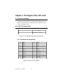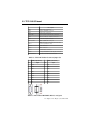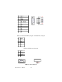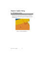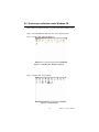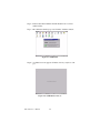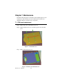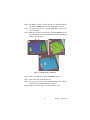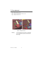
1
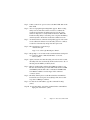
TPC-1240
RISC-based operator
interface terminal
with 12.1” flat panel
display
Users Manual
Copyright
This document is copyrighted March, 2002, by Advantech Co., Ltd. All
rights are reserved. Advantech Co., Ltd. reserves the right to make
improvements to the products described in this manual at any time. Specifications are thus subject to change without notice.
No part of this manual may be reproduced, copied, translated, or transmitted in any form or by any means without the prior written permission of
Advantech Co., Ltd. Information provided in this manual is intended to
be accurate and reliable. However, Advantech Co., Ltd., assumes no
responsibility for its use, nor for any infringements upon the rights of
third parties which may result from its use.
Acknowledgements
TPC-1240 is a trademark of Advantech Co., Ltd. IBM, PC/AT, and PS/2
are trademarks of International Business Machines Corporation. MSDOS and Windows CE are trademarks of Microsoft Corporation. iCava is
a trademark of Avamax Incorporated.All other brand and product names
mentioned herein are trademarks or registered trademarks of their respective holders.
Part No. 2006124000
Printed in Taiwan
TPC-1240 User’s Manual
ii
1st Edition
February 2002
FCC Class A
This equipment has been tested and found to comply with the limits for a
Class A digital device, pursuant to Part 15 of the FCC Rules. These limits
are designed to provide reasonable protection against harmful interference when the equipment is operated in a commercial environment. This
equipment generates, uses and can radiate radio frequency energy. If not
installed and used in accordance with this user's manual, it may cause
harmful interference to radio communications. Operation of this equipment in a residential area is likely to cause harmful interference, in which
case the user will be required to correct the interference at his own
expense.
Warning:
Any changes or modifications made to the
equipment which are not expressly approved
by the relevant standards authority could void
your authority to operate the equipment.
iii
Packing List
In the whole set of TPC-1240 there are items as listed below:
• TPC-1240T-CE (or TPC-1240T-LNX) x 1 unit; the Windows CE (or
Linux) operating system image is built in the flash memory on board.
• Accessory kit which includes:
1.
Panel mounting clamps x 8 pieces
2.
Panel mounting screws x 8 pieces
3.
3-pin power connector x 1 piece
4.
Support CD x 1 piece
5.
1 meter 9-pin to 9-pin null modem cable x 1 piece
6.
Microsoft Windows CE end user license agreement x 1 piece*1
7.
TPC-1240 Linux resource CD x 1 piece *2
Remarks:
1. Only available in the model bundled with
Windows CE OS
2. Only available in the model bundled with
Linux.
Additional Information and Assistance
1.Visit the Advantech web site at www.advantech.com where you can
find the latest information about the product.
2.Contact your distributor, sales representative, or Advantech's customer
service center for technical support if you need
additional assistance. Please have the following information ready before
you call:
•Product name and serial number
•Description of your peripheral attachments
•Description of your software (operating system, version, application
software, etc.)
•A complete description of the problem
•The exact wording of any error messages
TPC-1240 User’s Manual
iv
Safety Instructions
1. Read these safety instructions carefully.
2. Keep this User's Manual for later reference.
3. Disconnect this equipment from any AC outlet before cleaning. Use a damp
cloth. Do not use liquid or spray detergents for cleaning.
4. For plug-in equipment, the power outlet socket must be located near the
equipment and must be easily accessible.
5. Keep this equipment away from humidity.
6. Put this equipment on a reliable surface during installation. Dropping it or letting it fall may cause damage.
7. The openings on the enclosure are for air convection. Protect the equipment
from overheating. DO NOT COVER THE OPENINGS.
8. Make sure the voltage of the power source is correct before connecting the
equipment to the power outlet.
9. Position the power cord so that people cannot step on it. Do not place anything
over the power cord.
10. All cautions and warnings on the equipment should be noted.
11. If the equipment is not used for a long time, disconnect it from the power
source to avoid damage by transient overvoltage.
12. Never pour any liquid into an opening. This may cause fire or electrical shock.
13. Never open the equipment. For safety reasons, the equipment should be
opened only by qualified service personnel.
14. If one of the following situations arises, get the equipment checked by service
personnel:
a. The power cord or plug is damaged.
b. Liquid has penetrated into the equipment.
c. The equipment has been exposed to moisture.
d. The equipment does not work well, or you cannot get it to work according
to the user's manual.
e. The equipment has been dropped and damaged.
f. The equipment has obvious signs of breakage.
15. DO NOT LEAVE THIS EQUIPMENT IN AN ENVIRONMENT WHERE
THE STORAGE TEMPERATURE MAY GO BELOW -20° C (-4° F) OR
ABOVE 60° C (140° F). THIS COULD DAMAGE THE EQUIPMENT. THE
EQUIPMENT SHOULD BE IN A CONTROLLED ENVIRONMENT.
The sound pressure level at the operator's position according to IEC 704-1:1982 is
no more than 70dB (A).
DISCLAIMER: This set of instructions is given according to IEC 704-1. Advantech disclaims all responsibility for the accuracy of any statements contained
herein.
v
Wichtige Sicherheishinweise
1. Bitte lesen sie Sich diese Hinweise sorgfältig durch.
2. Heben Sie diese Anleitung für den späteren Gebrauch auf.
3. Vor jedem Reinigen ist das Gerät vom Stromnetz zu trennen. Verwenden Sie
Keine Flüssig-oder Aerosolreiniger. Am besten dient ein angefeuchtetes Tuch
zur Reinigung.
4. Die NetzanschluBsteckdose soll nahe dem Gerät angebracht und leicht
zugänglich sein.
5. Das Gerät ist vor Feuchtigkeit zu schützen.
6. Bei der Aufstellung des Gerätes ist auf sicheren Stand zu achten. Ein Kippen
oder Fallen könnte Verletzungen hervorrufen.
7. Die Belüftungsöffnungen dienen zur Luftzirkulation die das Gerät vor überhitzung schützt. Sorgen Sie dafür, daB diese Öffnungen nicht abgedeckt werden.
8. Beachten Sie beim. AnschluB an das Stromnetz die AnschluBwerte.
9. Verlegen Sie die NetzanschluBleitung so, daB niemand darüber fallen kann.
Es sollte auch nichts auf der Leitung abgestellt werden.
10. Alle Hinweise und Warnungen die sich am Geräten befinden sind zu
beachten.
11. Wird das Gerät über einen längeren Zeitraum nicht benutzt, sollten Sie es vom
Stromnetz trennen. Somit wird im Falle einer Überspannung eine Beschädigung vermieden.
12. Durch die Lüftungsöffnungen dürfen niemals Gegenstände oder Flüssigkeiten
in das Gerät gelangen. Dies könnte einen Brand bzw. elektrischen Schlag auslösen.
13. Öffnen Sie niemals das Gerät. Das Gerät darf aus Gründen der elektrischen
Sicherheit nur von authorisiertem Servicepersonal geöffnet werden.
14. Wenn folgende Situationen auftreten ist das Gerät vom Stromnetz zu trennen
und von einer qualifizierten Servicestelle zu überprüfen:
a - Netzkabel oder Netzstecker sind beschädigt.
b - Flüssigkeit ist in das Gerät eingedrungen.
c - Das Gerät war Feuchtigkeit ausgesetzt.
d - Wenn das Gerät nicht der Bedienungsanleitung entsprechend funktioniert
oder Sie mit Hilfe dieser Anleitung keine Verbesserung erzielen.
e - Das Gerät ist gefallen und/oder das Gehäuse ist beschädigt.
f - Wenn das Gerät deutliche Anzeichen eines Defektes aufweist.
Der arbeitsplatzbezogene Schalldruckpegel nach DIN 45 635 Teil 1000
beträgt 70 dB(A) oder weiger.
DISCLAIMER: This set of instructions is given according to IEC704-1.
Advantech disclaims all responsibility for the accuracy of any statements
contained herein.
TPC-1240 User’s Manual
vi
Table of Contents
Contents
Chapter
1 General Information ........................................1
1.1
1.2
1.3
Introduction ....................................................................... 2
Specifications ................................................................... 3
LCD Specifications ........................................................... 4
1.4
Touchscreen Specifications............................................... 5
1.5
1.6
Power................................................................................. 5
I/O Ports Arrangement ...................................................... 5
1.7
Mounting ........................................................................... 6
1.8
Exploded diagram ............................................................. 7
1.9
Dimensions and cutout ...................................................... 8
Table 1.1: LCD specifications ............................................ 4
Table 1.2: Touchscreen Specifications ............................... 5
Figure 1.1: I/O Ports arrangement......................................... 6
Figure 1.2: Panel mounting ................................................... 6
Figure 1.3: Exploded diagram............................................... 7
Figure 1.4: Dimensions and cutout ....................................... 8
Chapter
2 System Quick Starting .....................................9
2.1
Unpacking and Powering up ........................................... 10
Figure 2.1:
Figure 2.2:
Figure 2.3:
Figure 2.4:
Figure 2.5:
Chapter
Opening the box................................................ 10
Unpacking the unit............................................ 10
Power connector and power lines ..................... 11
Power connector pin assignment ...................... 12
Plug in the power lines and turn on the power
switch12
3 The Engine of the TPC-1240 .........................13
3.1
3.2
Passive backplane............................................................ 14
CPC-1110 main board..................................................... 14
Table 3.1: CPC-1110 main board connector/jumper list .. 14
Table 3.2: Connector pin assignments .............................. 14
3.3
TPC-1240 I/O board........................................................ 15
Table 3.3: TPC-1240 I/O board connector/jumper list ..... 15
Table 3.4: TPC-1240 COM1/COM3 (RS-232) serial ports...
15
Table 3.5: TPC-1240 COM2 (auto flow control RS-485) serial port 16
Table 3.6: LCD inverter connector ................................... 16
Table 3.7: Power connector .............................................. 16
Table 3.8: 16-bit LCD display connector ......................... 17
Table 3.9: Touchscreen interface connector ..................... 18
i
Chapter
4 Windows CE in the TPC-1240 .....................19
4.1
Introduction ..................................................................... 20
4.2
TPC Utilities.................................................................... 21
Figure 4.1: Windows CE on TPC-1240 .............................. 20
Figure 4.2: Soft-keyboard ................................................... 21
Figure 4.3: TPC Configurator ............................................. 22
Figure 4.4: TPC Configurator ............................................. 23
Figure 4.5: Calibrating Tapping location ............................ 23
Figure 4.6: Screen for calibration........................................ 24
Figure 4.7: LCD control utility ........................................... 25
Figure 4.8: Watchdog timer settings ................................... 25
Figure 4.9: Miscellaneous ................................................... 26
Figure 4.10:Default names for the CF card ......................... 27
Figure 4.11:Regflash ........................................................... 28
4.3
Networking...................................................................... 29
Figure 4.12:Control panel.................................................... 29
Figure 4.13:Networking by Windows Explorer .................. 30
Figure 4.14:Remote Networking ......................................... 31
Figure 4.15:Make new connection ...................................... 31
Figure 4.16:Direct connection ............................................. 32
Figure 4.17:default settings ................................................. 32
Figure 4.18:Default settings (cont)...................................... 33
Figure 4.19:Web browser on TPC-1240.............................. 33
4.4
Application program development.................................. 33
Figure 4.20:Flowchart of building Windows CE runtime... 35
Chapter
5 Linux in the TPC-1240...................................37
5.1
Technology...................................................................... 38
5.2
5.3
Linux components on the TPC-1240 .............................. 40
Boot Up the TPC-1240 with Linux ................................. 40
Figure 5.1: Structure of iCava ............................................. 39
Chapter
6 System Tuning ................................................43
6.1
LCD brightness tuning .................................................... 44
6.2
Touchscreen calibration under Windows CE.................. 45
Figure 6.1: Adjust LCD brightness ..................................... 44
Figure 6.2:
Figure 6.3:
Figure 6.4:
Figure 6.5:
Figure 6.6:
Chapter
Double click “Windows explorer”.................... 45
Control panel .................................................... 45
Calibration ........................................................ 46
Calibration screen (1) ....................................... 46
Calibration screen (2) ....................................... 47
7 Maintenance....................................................49
7.1
CPU board replacement .................................................. 50
Figure 7.1: CPU board cover............................................... 50
Figure 7.2: Remove the CPU board cover .......................... 50
ii
Table of Contents
Figure 7.3: Remove the CPU board .................................... 51
7.2
Fuse replacement............................................................. 52
Figure 7.4: Replace the fuse................................................ 52
Appendix A Fuse Specifications .........................................53
A.1
Supported Input Timing Modes ...................................... 54
Appendix B Registry searching sequence of TPC-1240...55
B.1
Supported Input Timing Modes ...................................... 56
Figure B.1: Windows CE registry searching algorithm flowchart56
iii
iv
C H A PT E R
1
General Information
This chapter gives background
information on the TPC-1240.
Sections include:
• Introduction
• Specifications
• LCD Specifications
• Touchscreen specifications
• Power
• I/O ports
• Mounting
• Exploded diagram
• Dimensions and cutout
1
Chapter 1 General Information
Chapter 1 Introduction
1.1 Introduction
The TPC-1240 touch panel computer is an excellent product for HMI
(Human Machine Interface). This 12.1” display operator interface is a
RISC-based platform with these key features:
- All in one platform: the CPU, DRAM and Windows CE (or Linux) are
integrated.
Please refer to chapter 4 for details about Windows CE inside, and to
chapter 5 for details about Linux.
- Slim but robust: the TPC-1240 is very thin (50 mm thickness) and
lightweight (2.2 kg). This makes it the best solution for those applications that are tough in space or weak structural support.
- Cost effective: applying a high brightness TFT LCD with SVGA resolution (800 x 600). The TPC-1240 offers cost effective solution for
operator interface terminals. With proper application programs it
would give a comfortable graphic user interface (GUI) at this size of
display.
- Fan-less and modular CPU board: the introduction of low power processor prevents this system from unreliable fans. In addition, the modular design facilitates the maintenance or possible upgrade on the
CPU board.
- Powerful communication capability: the TPC-1240 provides serial
ports and Ethernet communication. These two means of communication are the most welcomed ones in the field of industrial automation.
- Windows CE support: Advantech provides platform support for Windows CE. The operating system is built-in, the SDK for user-defined
application programs are freely offered.
- Linux support: the TPC-1240 is also powered by Avamax iCava,
which is a complete Linux package including kernel, development
tools and source codes.
TPC-1240 User’s Manual
2
1.2 Specifications
1.2.1 System kernel (CPC-1110)
- CPU: Intel StrongARMTM SA1110 206 MHz RISC processor
- BIOS: there is no BIOS in RISC platform; similar functions are built
on board directly
- VGA: MediaQ MQ200 VGA controller
- DRAM: built-in 32 MB SDRAM
- Ethernet: SMSC LAN91C96I 10Base-T Ethernet controller
- Watchdog timer: Dallas DS1670 watchdog timer; the time-out period
is programmable by driver.
- Floppy diskette: the TPC-1240 does not provide floppy disk interface
1.2.2 I/O Ports
- 3 serial ports: 9-pin RS-232 (COM1), RS-485 (COM2) and 2-pin RS232(COM3)
- 1 RJ-45 Ethernet port
1.2.3 Storage
- The primary storage device is the 16 MB built-in flash memory. The
default Windows CE or Linux operating system is in this device.
- The TPC-1240 provides one CompactFlash card slot. This slot is for
the storage of variety of Windows CE/Linux-based application programs.
1.2.4 Safety and Environment
Safety
- FCC class A and CE certificated
- BSMI certificated
- The front bezel is compliant with NEMA 4/IP65
Environment
- Operating temperature: 0~50° Celsius
- Storage temperature: -20~60° Celsius
3
Chapter 1 General Information
- Humidity: 10 ~ 95% @ 40° Celsius relative humidity (non-condensing)
- Vibration: 10 ~ 18 Hz: 1.5 mm peak-to-peak displacement; 18 ~ 500
Hz: 1 G acceleration.
1.3 LCD Specifications
Display Type
TFT color LCD
Size (Diagonal)
12.1"
Maximum Resolution
800 x 600 (SVGA)
Maximum Colors
256k
Pixel pitch (WxH, mm)
0.31 x 0.31
Viewing angle
100
Luminance (cd/m )
300
Contrast ratio
150 minimum
2
Operating temperature ( C)
0-50 (ambient)
VR control
Brightness adjustable
Backlight
2 CCFL
Backlight MTTF
50,000 hours
o
Table 1.1: LCD specifications
TPC-1240 User’s Manual
4
1.4 Touchscreen Specifications
Type
Resistive
Base glass construction
Tempered Glass
Resolution
Continuous
Light transmission
75% typical
Controller
PS/2 interface (simulated by SPI)
Power rating
3.3 to 5 V
Software driver
Windows CE or Linux (Embedded)
Durability
100 million touches
DC
Table 1.2: Touchscreen Specifications
1.5 Power
The TPC-1240 works by 24V power input. The maximum current is
about 0.8 A, and the nominal power consumption is 20 watts.
DC
Note:
In spite of the stated input voltage rating, the
TPC-1240 can operate using 18 ~ 30 VDC.
1.6 I/O Ports Arrangement
The TPC-1240 has 3 serial ports, 1 RJ-45 LAN port. The arrangement of
these ports is shown in Figure 1.1
5
Chapter 1 General Information
Figure 1.1: I/O Ports arrangement
1.7 Mounting
1.There is a piece of adhesive waterproof gasket on the plastic front
bezel. Make sure the waterproof gasket is in position before install the
TPC-1240 to the panel opening.
2.Install the TPC-1240 to the panel opening.
3.Find the eight clamps and eight long screws in the accessory pack.
Hook those clamps to those holes around the four sides of the bezel.
Insert the screws to every clamp and fasten them. These screws will
then push on the mounting panel and fix the unit.
4.The mounting panel thickness is suggested to be less than 6 mm (0.236
inch).
Figure 1.2: Panel mounting
TPC-1240 User’s Manual
6
1.8 Exploded diagram
Figure 1.3: Exploded diagram
7
Chapter 1 General Information
1.9 Dimensions and cutout
- Weight: 2.2 kg (without HDD)
- Dimension: 311 x 237 x 50 mm (W x H x D)
- Cutout: 302 x 228 mm (suggested)
Figure 1.4: Dimensions and cutout
TPC-1240 User’s Manual
8
C H A PT E R
2
System Quick Starting
This chapter provides a brief explanation
for operating the TPC-1240.
9
Chapter 2 System Quick Starting
Chapter 2 System Quick Starting
2.1 Unpacking and Powering up
Step 1
Unpack the TPC-1240 from its packaging. Please check the packing list
at the beginning of this manual.
Figure 2.1: Opening the box
Cushions
(P/N: 2130201590)
Accessory Box
(P/N: 2110002150)
Main Box
(P/N: 2110002430)
Figure 2.2: Unpacking the unit
TPC-642 User’s Manual
10
Step 2
Insert a CompactFlash memory card containing Windows CE or Linuxbased application program. Please refer to chapter 4 and 5 for building
applications for the TPC-1240.
Warning:
The CompactFlash memory card is not hot
swappable, it is recommended you turn off system power before installing the memory card.
Thus, potential data loss can be avoided.
Step 3
Connect the power connector to a 24 V power source. The power source
can either be from a power adapter or an in-house power source.
DC
Figure 2.3: Power connector and power lines
Warning:
If the power source is not connected to the correct pins, the system may be damaged when
the power is turned on.
Step 4
Plug the power source to the system power supply.
11
Chapter 2 System Quick Starting
Figure 2.4: Power connector pin assignment
Step 5
Plug in the power lines and turn on the system power switch.
Figure 2.5: Plug in the power lines and turn on the power switch
Step 6
Calibrate the touchscreen. Detailed procedures are described in section
5.3 for Linux and section 6.2 for Windows CE.
TPC-642 User’s Manual
12
C H A PT E R
3
The Engine of the
TPC-1240
This chapter briefly introduces the
CPU board and the I/O board
which comprise the system.
13 Chapter 3 The Engine of the TPC-1240
Chapter 3 The Engine of the TPC-1240
3.1 Passive backplane
The engine of the TPC-1240 is constructed by the combination of two
PCBA—one main board and one I/O board. Such combination makes
system customizing feasible.
3.2 CPC-1110 main board
Description
J1
TPC-1240 LCD control bus
Table 3.1: CPC-1110 main board connector/jumper list
3.2.1 Connector pin assignments
Pin
Signal
Pin
Signal
1
#CAS1
26
#CAS2
2
#CAS3
27
DCK0
3
DCK1
28
CKE0
4
CKE1
29
DCK2
5
#SDCS3
30
#SDCS2
6
#SDCS1
31
JTAG_TCK
7
#SDCS0
32
JTAG_TDI
8
#SDRAS
33
JTAG_TMS
9
#SDCAS
34
JTAGTDO
10
#CAS0
35
#JTAGTRST
Table 3.2: Connector pin assignments
TPC-1240 User’s Manual
14
3.3 TPC-1240 I/O board
D e s c rip tio n
C N2
5 0 -p in F P C c o nne c to r
C N3
1 4 4 -p in S O D IM M c o nne c to r
C N4
2 0 -p in F P C c o nne c to r
C N 6 /C N 7
P S /2 k e yb o a rd a nd m o us e c o nne c to r
C N8
E the rne t 1 0 B a s e -T R J -4 5 c o nne c to r
C N9
P o w e r D C inp ut c o nne c to r
C N 1 0 /C N 1 2
C O M 1 /C O M 3 R S -2 3 2 p o rts
C N 11
C O M 2 R S -4 8 5 s e ria l P o rt (a uto d a ta flo w
c o ntro l b y W ind o w s C E )
C N14
L C D c o nne c to r
C N15
V G A c o nne c to r
C N17
L C D inve rte r c o nne c to r
C N18
C o m p a c tF la s hTM s o c k e t 5 0 -p in c o nne c to r
J P 2 0 0 /J P 2 0 1
To uc hs c re e n inte rfa c e c o nne c to rs
Table 3.3: TPC-1240 I/O board connector/jumper list
COM1 (9-pin RS-232)
Pin
Signal
COM3 (2-pin RS-232)
Pin
Signal
1
DCD
1
N/C
2
RXD
2
RXD
3
TXD
3
TXD
4
DTR
4
N/C
5
GND
5
GND
6
DSR
6
N/C
7
RTS
7
N/C
8
CTS
8
N/C
9
RI
9
N/C
Table 3.4: TPC-1240 COM1/COM3 (RS-232) serial ports
15 Chapter 3 The Engine of the TPC-1240
Pin
Signal
1
DATA-
2
DATA+
3
N/C (TX232)
4
N/C (RX232)
5
GND
6
N/C
7
N/C
8
N/C
9
N/C
Table 3.5: TPC-1240 COM2 (auto flow control RS-485) serial port
Pin
Signal
1
12V
2
GND
3
ENABKL
4
VBR
5
N/C
Table 3.6: LCD inverter connector
Pin
Signal
1
24VDC(+)
2
24VDC(-)
3
GND
Table 3.7: Power connector
TPC-1240 User’s Manual
16
Pin
Signal
Pin
Signal
1
VDDSAFE5
2
VDDSAFE5
3
GND
4
GND
5
VDDSAFE3
6
VDDSAFE3
7
Vcon
8
GND
9
LCD_D0
10
LCD_D1
11
LCD_D2
12
LCD_D3
13
LCD_D4
14
LCD_D5
15
LCD_D6
16
LCD_D7
17
LCD_D8
18
LCD_D9
19
LCD_D10
20
LCD_D11
21
LCD_D12
22
LCD_D13
23
LCD_D14
24
LCD_D15
25
N/C
26
N/C
27
N/C
28
N/C
29
N/C
30
N/C
31
N/C
32
N/C
33
GND
34
GND
35
SHCLK
36
FLM
37
M/DE
38
LP
39
ENABKL
40
ENAVEE
Table 3.8: 16-bit LCD display connector
17 Chapter 3 The Engine of the TPC-1240
Pin
Signal
1
SENSE_XL
2
SENSE_XR
3
SENSE_YT
4
SENSE_YB
Table 3.9: Touchscreen interface connector
TPC-1240 User’s Manual
18
C H A PT E R
4
Windows CE in the
TPC-1240
19 Chapter 4 Windows CE in the TPC-1240
Chapter 4 Windows CE in TPC-1240
4.1 Introduction
The TPC-1240 operator interface terminal is designed to serve on the
Windows CE platform. The Windows CE is a compact operating system
that occupies less storage space or system resources compared with other
operating systems. By its modular nature, it is possible to choose those
functions that are useful for specific application. Not only reducing the
system resources required, it also reduces start-up time. In the field of
industrial automation or for operator interface terminal, this is an appealing feature because the impact of downtime would be minimized. Furthermore, the small storage space it needs makes operating system on
solid-state disk possible.
Notice:
Default Windows CE inside the TPC-1240 is
the English version. Please contact Advantech
local representatives for local language support.
Figure 4.1: Windows CE on TPC-1240
TPC-1240 User’s Manual
20
4.2 TPC Utilities
There are several useful utilities built in the standard Windows CE OS of
TPC-1240:
4.2.1 Soft-Keyboard
The TPC-1240 is dedicated to the small-sized operator interface. It is
often inconvenient for users to attach a keyboard to such small machine.
Thus, a software keyboard is embedded in the standard TPC-1240 OS.
Upon boot-up, a small keyboard icon will appear on the status bar. Tap
this icon by the stylus to activate/hide this Soft-keyboard.
Figure 4.2: Soft-keyboard
21 Chapter 4 Windows CE in the TPC-1240
4.2.2 TPC Configurator
TPC-1240 provides an integrated utility for users to make basic settings
of the machine.
Figure 4.3: TPC Configurator
General information
As shown in the Figure 4.3, the first page of the TPC configurator gives
the general information of the TPC-1240. Note that if there is no CompactFlash memory card is inserted, the figures shown will be zero for this
item.
Notice the version numbers shown on this page. The format of the version
number is: Va.bb.c
a: stands for the major version number. Only for structural revision of the
OS will this number be changed.
bb: stands for minor version number. The first digit changes when substantial revision is made, while the second digit changes for minor revision.
c: stands for pre-release version. From time to time it is possible that
users get such pre-release version to keep time-to-market. When this digit
appears, it means that this version is built and tested by Advantech Windows CE R&D team. When such "beta" version finishes all necessary
quality assurance procedure and get into mass production, this digit will
be taken away.
TPC-1240 User’s Manual
22
Touchscreen calibration
The touchscreen calibration can be executed from the configurator.
Figure 4.4: TPC Configurator
Tap the "Calibrate" button shown in the Figure 4.4, the calibration utility
is activated. It allows users to adjust both tapping location and double tapping interval.
Figure 4.5: Calibrating Tapping location
23 Chapter 4 Windows CE in the TPC-1240
Tapping the "Recalibrate" button, the screen will turn out to be white. A
cross appears at the center of the screen. Use a stylus or finger to push the
center of the cross until it moves. The cross moves to upper-left, lowerleft, lower-right and upper-right corners. Push the center to give location
references. When all five crosses are done, click "OK" button and the settings will be automatically saved to the registry.
Figure 4.6: Screen for calibration
LCD Control
Display page of the TPC Configurator provides the function to turn off
the LCD backlight, and thus elongates the period of service. For example,
if the user wants the backlight turned off automatically after 10 seconds
when the device was no longer used. The user must choose the “Turn off
backlight after second”, type in “10” in the edit box and then press
“Apply” button. Then the screen save function is enabled. In addition,
users can click the “Off Now” button to turn off the backlight of the display panel immediately. Once the backlight was turned off, events or perturbations from the touchscreen can turn it on.
On the other hand, if users want to disable the screen save function,
choose “Always On” radial button and press “Apply” button.
TPC-1240 User’s Manual
24
Figure 4.7: LCD control utility
Watchdog timer
It is important in industrial applications that the control systems are rarely
down, or are capable of self-reset if they are halted somehow. The watchdog timer is therefore used in the TPC-1240 to provide automatic reset.
There is a timer inside the watchdog timer. The TPC-1240 should clear
the timer within a pre-set time interval periodically. If the timer is not
cleared, the timer would assume the system to be halted and generate a
reset. The watchdog timer in the TPC-1240 provides eight different time
intervals: 2 seconds, 5 seconds, 10 seconds, 30 seconds, 60 seconds, 2
minutes, 5 minutes and 10 minutes. Choose the appropriate time interval,
and then press "Enable" button to enable the watchdog function. The
"REBOOT" can immediately initiate a warm reboot.
Figure 4.8: Watchdog timer settings
25 Chapter 4 Windows CE in the TPC-1240
The RTC TIME region shown at the lower area of the Figure 4.8 displays
the time of watchdog timer (DS1670) and system time. Users can press
"Start" button to show the current time.
Miscellaneous
The last page of the configurator provides several miscellaneous but
important functions as described below. The buttons inside the "Registry"
area provide registry saving and browsing function. The "SMC MAC ID"
shows the network MAC address. The "HTTP Server Root" block is used
to specify the root directory of http server. The default directory was
"\Storage Card\", users can specify another directory by type the directory
in the edit box and press "Set" button. The new setting would become
effective after the system reboot. The buttons inside "COMM" area provides the communication functions including Activesync, IPConfig, and
to ping Yahoo!.
Figure 4.9: Miscellaneous
Notice:
There is a pull-down menu for users to set the
folder name of the CompactFlash memory
card. The default folder name is "Storage
Card".
Warning:
Do not try to key in folder name in the text box
directly. If the CF is rename to some name that
beyond the given list, there will be irreversible
problem for users' application program settings.
TPC-1240 User’s Manual
26
Figure 4.10: Default names for the CF card
27 Chapter 4 Windows CE in the TPC-1240
4.2.3 Saving registry
The window of the regflash utility is shown as Figure 4.11. There are
three options to handle the registry: to save registry on flashROM, to
delete registry on flashROM and to save registry to CompactFlash card.
Select the option and click "Save" button to activate.
Figure 4.11: Regflash
Notice:
Do not select "Save" and "Delete" registry on
flash at the same time. Such conflicting commands may cause unpredictable results.
Warning:
If there is no CompactFlash card inserted in the
CF slot, the option to save to CF disk will be
disabled.
The other function this utility can do is to wipe out the contents on the
IPSM (Intel Persistent Storage Manager). Select this option and click
"Save", the data stored in the IPSM (i.e., the spared space of the on-board
flashROM) will be deleted.
Warning:
After the IPSM is erased, if the machine is
restarted, it will hold for several minutes to format the IPSM. Do not turn off or interrupt the
formatting otherwise the operating system will
be corrupted.
TPC-1240 User’s Manual
28
4.3 Networking
4.3.1 Networking via ethernet
The TPC-1240 is equipped with a 10Base-T Ethernet controller. To utilize it, change the device name when the TPC-1240 is first turned on.
Step 1. Click “Start/Settings/Control Panel”
Figure 4.12: Control panel
Step 2. Double click “Communications”
Step 3. Find the default device name. Change it to a unique one depending on the plan of individual LANs.
Step 4. Use the utility mentioned in section 4.2.3 to save this changed
name
Step 5. If the TPC-1240 is a node of a LAN with DHCP servers, it is now
available.
Step 6. If the TPC-1240 is a node of a LAN with fixed IP server, please
consult with MIS to get specific IP address. Click “Start/Settings/Control Panel”. Double click “Network” and update the IP
address.
Step 7. Use the registry saving utility to save this changed name.
29 Chapter 4 Windows CE in the TPC-1240
Figure 4.13: Networking by Windows Explorer
4.3.2 Networking via serial port
The TPC-1240 with built-in Windows CE supports serial connection to
host computers. The host computer must install the Microsoft ActiveSync
service offered by Microsoft. Use a null modem cable bundled with the
TPC-1240 to connect the serial ports of the host computer and the TPC1240. Then activate ActiveSync service on the host computer. The host
will automatically scan its serial ports and make a connection.
Step 1. Make sure the Microsoft ActiveSync service and the Microsoft
embedded Visual Tools are properly installed in the host PC.
Step 2. Connect the two RS-232 ports of the host PC and the TPC-1240
by a null modem cable.
Step 3. If users are using the Microsoft eMbedded Visual Tools to
develop Windows CE application runtimes, make sure the TPC1240 SDK provided in the TPC-1240 support CD is also properly installed in the host PC.
Step 4. Click "Start/Programs/Communication/Remote Networking"
TPC-1240 User’s Manual
30
Figure 4.14: Remote Networking
Step 5. Make a new connection. As the dialogue box pops out, choose
the default "Direct Connection".
Figure 4.15: Make new connection
31 Chapter 4 Windows CE in the TPC-1240
Figure 4.16: Direct connection
Step 6. Click "Next" and "Finish" to complete making new connection. It
is recommended to keep the default settings of the serial ports
connection.
Figure 4.17: default settings
TPC-1240 User’s Manual
32
Figure 4.18: Default settings (cont)
Step 7. If the ActiveSync service on the host PC has been activated, the
above six steps will make the TPC-1240 automatically try to
connect the host.
Figure 4.19: Web browser on TPC-1240
4.3.3 Web browser
The TPC-1240 built-in Windows CE OS includes Microsoft IE Sample. It
can be used to browse web pages on World Wide Web via LAN or dial-up
connection.
4.4 Application program development
The TPC-1240 is bundled with built-in Windows CE operating system. In
real applications users need to execute various application programs on it.
However, unlike its other family the Windows CE is a hardware-dependent operating system. That is to say, Windows CE application programs
33 Chapter 4 Windows CE in the TPC-1240
are only portable in the source code level. Users must rebuild the runtime
file for a different Windows CE platform even though the source code
may not be changed at all.
4.4.1 System requirements for developers
- Intel Pentium-90 CPU or more advanced
- Microsoft Windows 2000 Professional or Windows NT Workstation
4.0
- Microsoft eMbedded Visual Tools 3.0
- Platform SDK for TPC-1240 (bundled in the standard TPC-1240SCE)
- 64 MB DRAM
- CD-ROM drive
- Monitor with VGA resolution at least
- Mouse
- 200 MB free hard disk space at least
- Connection to the same LAN as the TPC-1240 if LAN is used for
development TPC-1240
- TPC-1240S-CE
- Connection to the same LAN as the host PC if LAN is used for
development
- Null modem cable (bundled in the standard TPC-1240S-CE)
4.4.2 Building Windows CE Runtime
By the platform SDK bundled with the standard TPC-1240, users can
build the Windows CE runtime by the eMbedded Visual Tools.
TPC-1240 User’s Manual
34
Figure 4.20: Flowchart of building Windows CE runtime
4.4.3 Startup Execution
The TPC-1240 has a useful function called "startup execution". After the
system is finished booting up, the startup execution function would automatically be performed. This function is useful for control systems to do
initialization processes or some other programs. On the TPC-1240, there
are two ways to perform the "Starup" function.
Method 1: single execution program
Step 1. Create a "startup" directory on the CompactFlash card or on the
IPSM if there is no CF used.
Step 2. Copy the executable file to the "startup" directory.
Example:
We copy an executable file "Xaudio.exe" in "\IPSM\Startup", and then
reboot the system. Then Xaudio.exe will automatically execute.
Notice:
Do not put two or even more executable files
on the startup directory. Under such circumstance the execution sequence is unpredictable.
35 Chapter 4 Windows CE in the TPC-1240
Method 2: multiple execution programs
Step 1. Create a "startup" directory on the CompactFlash card or on the
IPSM if there is no CF used.
Step 2. Create a file called "startup.ini" in the "startup" directory. In this
startup.ini type in the commands you want to execute as boot up.
Example:
Create "Startup.ini" in the "\IPSM\Startup" directory and reboot the system.
The content of startup.ini is listed below:
\windows\tty.exe
\windows\registry.exe
As the system reboots, "\windows\tty.exe" and "\windows\registry.exe"
will execute automatically.
Notice:
Do not use method 1 and 2 simultaneously.
The sequence to execute programs would be
unpredictable.
TPC-1240 User’s Manual
36
C H A PT E R
5
Linux in the TPC-1240
37
Chapter 5 Linux in the TPC-1240
Chapter 5 Linux in the TPC-1240
The TPC-1240 has optional package of Linux operating system. Cooperating with Avamax, the Linux package called "iCava" is available. This
chapter discloses some briefing for it. Please refer to the iCava resource
CD for more detailed technical reference.
5.1 Technology
iCava is a collection of software in such a way that it can be tailored for
various kinds of Internet access devices. It consists of a micro-kernel OS,
a flash file system, IC card support, multi-lingual multi-window GUI,
TCP/IP protocols stack, Secure Socket Layer, PPP, Web Browser, MIME
e-mail, NetMeeting compatible video phone with software CODEC, software MP3 player, MS Outlook-like PIM, spread sheet and HTML-based
word processor
The iCava technology deals with:
1.
accessing the Internet
2.
un-compromised web browsing
3.
multi-media communication
4.
graphical user interface
5.
embedded window management
6.
embedded file management
7.
hardware resource management
8.
embedded data and information management
Figure 5.1 shows the structure of iCava
TPC-1240 User’s Manual
38
Figure 5.1: Structure of iCava
39
Chapter 5 Linux in the TPC-1240
5.2 Linux components on the TPC-1240
Among the superior technologies of iCava, some of them are selected for
the TPC-1240 so as to meet the requirements in the field of human
machine interface. The components include:
1.
Linux kernel version 2.4.3
2.
gLibC version 2.2.1
3.
Drivers:
- SA1110 LCD driver
- UCB1300 Touchscreen driver
- PS/2 to SPI (Serial Protocol Interface) keyboard/mouse driver
- CompactFlash support driver
- SMC91C96 LAN driver
- RS-232 serial port driver (COM1)
- RS-485 serial port driver (COM2)
iCava GUI (Graphic User Interface):
The iCava GUI for 320 x 240 (QVGA) English version is built-in though
the kernel looks like a command-line based OS. If users need the iCava
GUI, the resource CD gives all necessary information about iCava API.
5.3 Boot Up the TPC-1240 with Linux
To keep the flexibility that Linux has, the TPC-1240 shows the Linux
kernel only. The GUI is left to users for customizing. It is very possible
that users have their own GUI, or they intend to develop their own GUI.
The following is the step-by-step boot up procedure of the TPC-1240
with Linux.
Notice:
Since Linux is a command-line based operating
system, it is necessary for users to connect a keyboard to the TPC-1240 with Linux at the first time.
As iCava or other GUI/window manager is
installed, the touchscreen might take place of the
keyboard.
TPC-1240 User’s Manual
40
Step 1. Connect some 24 V power source to the TPC-1240. Turn on the
TPC-1240.
DC
Step 2. An icon of penguin representing Linux appears. Then a testing
utility activates. The first screen is for users to calibrate the
touchscreen. After that, the utility turns out to be the screen
which can help users to verify hardware functions. When this
hardware testing utility is activating, users can press the F10 key
on the keyboard to invoke the touchscreen calibration screen.
Step 3. As mentioned above, when the testing utility appears after touchscreen calibration and users leave the utility alone for a while, it
would close automatically and get into the login screen.
Step 4. The screen shows a login message:
Advantech Login:
Type "root" as the login ID and press "Enter".
Step 5. The prompt is a "#". If users need to run the hardware testing utility (again), key in the command and "Enter" to execute.
#icava (enter)
Step 6. Again, if users do not enter the testing screen for several seconds,
the utility will close automatically. If the touchscreen is to be calibrated, press the F10 key of the keyboard.
Step 7. There is another utility verifying the COM ports. There is one
RS-232 and one RS-485 port on the TPC-1240. Connect COM1
and COM2 by null modem cable or Advantech ADAM-4520/
4522 RS232 to RS485 converter. Type in the command
"comtest" (enter).
Step 8. The utility then begins to test bi-directional data transmission
between the two serial ports. If everything is fine, the test will
stop after 115200 bps is verified.
Step 9. To show the local IP address, type the command "ifconfig"
(enter).
Step 10. To test networking, type in the command in the command line:
#ping xxx.xxx.xxx.xxx (enter)
41
Chapter 5 Linux in the TPC-1240
TPC-1240 User’s Manual
42
C H A PT E R
6
System Tuning
From time to time it is necessary to
tune system settings from the
defaults. The most common ones
are included in this chapter.
43
Chapter 6 System Tuning
Chapter 6 System Tuning
6.1 LCD brightness tuning
The display brightness of the TPC-1240 is designed to be adjustable.
There is an access opening at the rear case of this machine. Use a blade
screwdriver to reach the variant resistor inside, and adjust the contrast to
satisfactory level.
Figure 6.1: Adjust LCD brightness
TPC-1240 User’s Manual
44
6.2 Touchscreen calibration under Windows CE
The touchscreen calibration utility program is built in the Windows CE:
Step 1. From the Windows CE status bar, click “Start/Programs”
Step 2. Double-click “Windows Explorer”
Figure 6.2: Double click “Windows explorer”
Step 3. Double-click “Control Panel”
Figure 6.3: Control panel
45
Chapter 6 System Tuning
Step 4. In the Control Panel window find the"Touchscreen" icon and
double-click it.
Step 5. The calibration window pops out. Click the "Calibrate" button..
Figure 6.4: Calibration
Step 6. A calibration screen appears. Click the circle by a stylus or a finger.
Figure 6.5: Calibration screen (1)
TPC-1240 User’s Manual
46
Step 7. The second calibration screen appears. Click the circle again.
Figure 6.6: Calibration screen (2)
Step 8. Click "OK" to save the calibration results.
47
Chapter 6 System Tuning
TPC-1240 User’s Manual
48
C H A PT E R
7
Maintenance
In practice users may need on site
maintenance. This chapter covers several simple repairings that can be done
by qualified technicians.
49
Chapter 7 Maintenance
Chapter 7 Maintenance
The TPC-1240 is designed to be modular, slim and lightweight for easier
maintenance. The following sections are dedicated to describe how a
qualified technician can replace major components._
7.1 CPU board replacement
Step 1. Remove the screw on the CPU board cover.
Step 2. Slide the CPU board cover toward the opposite side of the I/O
ports.
Figure 7.1: CPU board cover
Step 3. Remove the CPU board cover.
Figure 7.2: Remove the CPU board cover
TPC-642 User’s Manual
50
Step 4. The CPU board is now visible. It connects to the I/O board by a
144-pin SO-DIMM connector and a 20-pin FPC connector.
Step 5. Use a pair of tweezers to loosen the 20-pin FPC connector, and
release the FPC.
Step 6. Bend outward the two metal latches of the SO-DIMM connector
by your thumbs. The free end of the CPU board would swing up.
Pull out the CPU board.
Figure 7.3: Remove the CPU board
Step 7. Insert a new CPU board to the SO-DIMM connector.
Step 8. Push down and lock the CPU board.
Step 9. Use a pair of tweezers to insert the 20-pin FPC to the connector
on the CPU board. Then tighten the connector.
Step 10. Replace the CPU board cover and fasten the screw.
51
Chapter 7 Maintenance
7.2 Fuse replacement
Step 1. Remove the fuse cover.
Step 2. Replace the damaged fuse with a new one.
Step 3. Replace the fuse cover.
Figure 7.4: Replace the fuse.
Warning:
1. Do not replace the fuse unless it is damaged
2. Do not replace the fuse with a fuse with a different rating.
TPC-642 User’s Manual
52
A p p en d ix
A
Fuse Specifications
53
Appx. A
Appendix A Fuse specifications
A.1 Supported Input Timing Modes
The fuse used on the TPC-1240 is:
Rating: 250 VAC, 5 A
Size: 5 x 20 mm
TPC-642 User’s Manual
54
A p p en d ix
B
Registry searching
sequence of TPC-1240
55
Appx. B
Appendix B Registry searching
sequence of TPC-1240
B.1 Supported Input Timing Modes
When the TPC-1240 is turned on, the Windows CE will search for registry to load those important system parameters. There are three alternatives to save the registry: registry file on the external CompactFlash
memory card, registry file on the built-in flash memory or default registry
settings in the Windows CE image file. Figure B.1 shows how TPC-1240
searches for the registry.
Power On
SAFEMODE*1
No
Registry on CF
No
Yes
Yes
Image on
Flash Memory
No
Image on
CompactFlash
Image on
CompactFlash
Image on
CompactFlash
No
No
Image on
Flash Memory
Image on
Flash Memory
No
No
Yes
Yes
Yes
Yes
Registry on
Flash Memory
Yes
Boot Failure*2
Boot Failure
Yes
Yes
Boot by Default
Registry
Boot by Registry
on CF
Boot Success
Boot Success
Boot by Registry
on Flash Memory
Figure B.1: Windows CE registry searching algorithm flowchart
TPC-642 User’s Manual
56
No
Remark:
1.
"SAFEMODE" implies a folder or an
empty file named "safemode" on the
CF. Users can create this by themselves as the registry on the flash memory might corrupt. Thus the bootup will
skip the registry on the flash memory.
2.
"Boot Failure" means the TPC-1240
fails to find necessary information. The
system will halt.
57
Appx. B
TPC-642 User’s Manual
58