1
R&S®RT‑ZD10/20/30
Putting into Operation
Offset Compensation
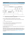
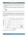
compensation is directly visible on the oscilloscope screen as a voltage offset of
the measured waveform.
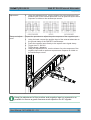
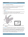
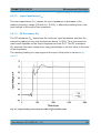
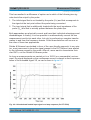
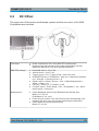
Fig. 2-2: Differential offset compensation for a single-ended measurement (negative input
connected to ground) using an R&S RT‑ZD10/20/30
To set the differential offset compensation on the front panel
1. Press the Vertical Position knob until the "Offset" setup is shown on the display.
2. Turn the Vertical Position knob.
To set the differential offset compensation using the probe menu
1. On the "Vertical" menu, select "Probe Setup".
2. Select the channel and tap "Offset".
For more details on setting the offset compensation, refer to the "User Manual" of
the R&S oscilloscope.
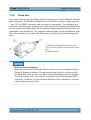
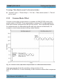
Additionally, the probe offers automatic offset compensation by means of the
micro button. A single push on the micro button compensates the DC component
of the measurement signal which is particularly helpful during measurements of
input signals with different DC offsets (see also chapter 2.2, "Micro Button",
on page 22).
User Manual 1410.4550.02 ─ 03
23