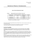
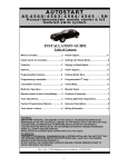
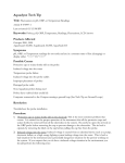
1
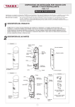
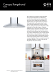
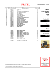
TEPPANYAKI
PROUDLY AUSTRALIAN MADE
INSTALLATION PROCEDURE – USER MANUAL
SERVICE INSTRUCTION
MODELS TK-24 TK-30 TK-36 TK-45
ESTABLISHED 1911
The Cooking Equipment Professionals
www.goldsteineswood.com.au
TABLE OF CONTENTS
1.
INTRODUCTION
Page 3
2.
INSTALLATION
Page 4 & 5
3.
COMMISSIONING
Page 6 & 7
4.
OPERATING INSTRUCTIONS
Page 8
5.
PILOT & BURNER OPERATION
Page 9
6.
TECHNICAL INSTRUCTIONS
Page 10
7.
TECHNICAL DATA
Page 11
8.
CLEANING INSTRUCTIONS
Page 12
9.
TEPPANYAKI TABLE
Page 13
10.
DRAWINGS
Page 14
11.
SPARE PARTS-DRAWINGS
Page 15
12.
WARRANTY
Page 16
13.
BRANCHES
Page 17
IM083B1/p2
1. INTRODUCTION
Congratulations for purchasing your Goldstein commercial cooking
appliance.
J. Goldstein & Co. is a wholly owned Australian company and has been
operating since 1911, building high quality products. The information in
this manual will assist your installer and ensure correct location and
connection. Thoroughly read the user instructions and the user
maintenance sections, as understanding your products, its operation, and
its cleaning and service requirements will provide you with long and
satisfactory service. Failure to do so could shorten the life of the product
and decrease its efficiency. Please ensure only authorised service
technicians are called to any difficulties that may arise.
INTRODUCTION
GOLDSTEIN TEPPANYAKKI
MODELS TK-24, TK-30, TK-36,TK-45
GOLDSTEIN TEPPANYAKI PLATES are designed to give long and satisfactory
service and incorporate the best possible materials and workmanship. Proper
installation, adjustment and preventative maintenance are vitally important if
efficiency and appearance are to be maintained.
Read these instructions carefully as they contain important safety information
regarding the installation, use and maintenance of the appliance.
RECEIVING INSPECTION
• Check crates for handling damage.
“concealed” damage.
dealer.
After carefully uncrating, check for
Report any damage immediately to carrier and to
• Remove check all loose items from unit and check contents as found on back
of warranty cards.
• Check type and capacity of gas supply.
• The type of gas for which this Teppanyaki is factory adjusted can be seen on
the rating plate, located on the front Control Panel.
“THE EQUIPMENT MUST BE INSTALLED BY A
LICENSED GASFITTER”
IM083B1/p3
2. INSTALLATION INSTRUCTIONS
PRE-INSTALLATION OF THE TEPPANYAKI
1.
Check that there is sufficient clearance between doors and passageways
to move equipment into the cooking area.
2.
Remove banding and cardboard outer.
3.
Lift off wooden base.
4.
Push in legs and tap in with a hammer into tubes (If required mount on
stand (OPTIONAL)
INSTALLATION
(FOR AUTHORISED TECHNICIANS ONLY)
Note: AFTER ANY MAINTENANCE OR ADJUSTING OF GAS CONNECTED
COMPONENTS, A GAS LEAK TEST MUST BE CARRIED OUT, TO ENSURE
THERE ARE NO GAS LEAKING HAZARDS
Adequate ventilation must be provided by a hood with vent and exhaust fan.
Never make a direct connection between the unit and vent flue. Check there is
sufficient room between doors and other units to allow equipment to be moved
into position.
Check the data plate to ensure that the appliance is suitable for the gas supply to
which it is to be connected and for information relative to gas input. Etc.
Follow these instructions carefully.
1.
2
Set unit in correct position (ENSURE THERE IS A MIN 25mm REAR
WALL CLEARANCE FROM COMBUSTIBLE MATERIALS AND THAT
THE UNIT IS PLACED ON A FIRE PROOF BASE) and adjust feet using a
spirit level, checking from back to front and side to side.
Have a licensed gas fitter or our local gas company connect the appliance
to the mains pressure supply.
NOTE:
The appliance must be installed by an authorised person and in accordance with
the regulations of the local Gas Authority, AS5601/AG601 and any other
authority having jurisdiction. The appliance has been tested and preset before
leaving our factory, but small adjustments may be necessary to suit local
conditions. Correct operation of the appliance must be tested as part of the
installation procedure.
The governor supplied must be installed on the gas inlet to the appliance. This is
supplied as a loose item. Licensed Gasfitter should make connection to main gas
line. Install a manual shut-off valve in gas line to the appliance manifold and
union.
NOTE: Models operating on LP Gas will be supplied with a regulator as from
(1st January 2005) as new standard (AS4563/AG300).
IM083B1/p4
2. INSTALLATION INSTRUCTIONS
3.
All equipment must be sitting level for proper operation and combustion
where plinth type installation is made, plinth height and front overhang
must be 50 mm minimum. Levelling can be made by the use of metal
shims. For griddles where adjustable legs are provided, levelling can be
made easily due to the threaded construction of the legs.
Licensed plumber should make connection to main gas line. Install a hand
shut-off valve in gas line to the appliance manifold.
IM083B1/p5
3. COMMISSIONING INSTRUCTIONS
OPERATION
(FOR AUTHORISED TECHNICIANS ONLY)
Note: All the appliances that leave our factory have been tested and
adjusted according to the specifications for the required gas. The regulator
may have to be adjusted to achieve the required gas pressure
Note: Before igniting the Teppanyaki plate, remove the protective coating
on the plate with solvent (e.g. mentholated spirits).
Ensure that the pressure at the pressure test point on the manifold is as per the
rating plate. If the pressure is not the same use a screwdriver to adjust the
pressure regulator (turning screw clockwise will increase the pressure).
Turn the control knob to low and check that the flame size has decreased
substantially. If flame has not decreased, then using a small flat headed
screwdriver adjust the “min gas screw” on the front of the gas control until the min
flame gets to desired size (turning screw clockwise will decrease the flame size).
Turn the Teppanyaki plate off and apply a coating of cooking oil to the whole
griddle plate surface. Failure to do this will cause the warranty to be void.
NOTICE
PLEASE RETURN YOUR WARRANTY CARD
FAILURE TO DO SO WILL VOID
WARRANTY ON THE EQUIPMENT
IM083B1/p6
3. COMMISSIONING INSTRUCTIONS
To be carried out by Gasfitter or Authority service person
COMMISSIONING APPLIANCE – DETAILS, TESTING, CHECKING PRESSURE
ETC.
COMMISSIONING CHECK LIST
1.
CHECK FOR DAMAGE AND MISSING PARTS ON BACK OF
WARRANTY CARD.
2.
REMOVE ALL PLASTIC COATING FROM S/STEEL PANELS.
3.
MAKE SURE ALL PARTS ARE IN THEIR CORRECT POSITION E.G.
TRAYS BURNERS KNOBS.
4.
MAKE SURE ALL ELECTRIC AND GAS CONNECTIONS ARE
CORRECT AND TIGHT.
5.
LEVEL OFF UNIT LEFT TO RIGHT AND ALSO MAKE SURE THAT
FRONT IS JUST 3-4 MM LOWER TO ALLOW FOR FLUING.
6.
TURN ON GAS OR ELECTRICITY.
7.
ADJUST GAS PRESSURE WITH THREE-QUARTERS OF THE UNIT
RUNNING, ADJUST GAS PRESSURE.
NATURAL GAS
LPG
1.00 KPA
2.65 KPA
8.
TURN ON ONE AT A TIME TO MAKE SURE ALL IS WORKING E.G.
BURNER, RADIANT, GRIDDLE AND OVEN.
9.
SHOW CUSTOMER
A)
B)
C)
D)
10.
HOW TO WORK EQUIPMENT
HOW TO CLEAN
HOW TO PULL IT APART E.G. TRAYS, TRIVETS.
ALSO WHAT NOT TO DO, E.G. WATER WITH ELECTRICAL,
GREASE AND OIL IN CONTROLS.
CHECK TO MAKE SURE MANUALS AND WARRANTY CARDS ARE
THERE.
ALSO GO THROUGH MANUAL WITH CUSTOMER E.G. LIGHTING,
CLEANING.
WASH HOSES SHOULD NEVER BE USED ON THE APPLIANCE.
USE OF HOSES WILL VOID WARRANTY.
IM083B1/p7
4. OPERATING INSTRUCTIONS
GAS BURNERS
TK-24
TK-30
TK-36
TK-45
1 BURNER
1 BURNER
1 BURNER
2 BURNERS
The Burners are adjusted as described on Page 9.
Cooking is generally started towards the middle of the burner and then moved to
the area which is not directly over the burner and can be held there for final
finishing.
IM083B1/p8
5. PILOT & BURNER OPERATION
A
Q
Q
OFF
B
PILOT
XC
S MAX
XD
Q
S MIN
ÎSPARKER TO LIGHT PILOT
G
A=
B=
C=
D=
OFF
IGNITION POSITION – LIGHT PILOT – (If flame failure hold in for 10
seconds to establish pilot flame).
TURN TO FULL ON – MAX GAS FLOW, FURTHER ADJUSTMENT
BETWEEN POSITIONS C & D.
TURN TO MINIMUM FLOW – MIN. GAS FLOW TO MAINTAIN FLAME
(Adjustable to suit type of gas used.) as precise and accurate.
TO OPERATE:
Push in and turn knob to position “B”, light pilot burner and hold in for10
seconds to establish Pilot flame, release (pilot burner should remain alight)
and turn to position “C” for full flow of gas, for minimum gas flow turn to
position “D”
(Adjustable to suit type of gas used). Further adjustment of gas flow
between position C & D.
IM083B1/p9
6. TECHNICAL INSTRUCTIONS Cont’d
PILOTS
Polidoro 509. Gas to pilot is controlled through an injector spud. This spud
needs to be replaced when converting between L.P. and N.G. If appliance
cannot be correctly adjusted, advise the local gas authority or the appliance
manufacturer.
CONTROLS
The only controls are the PEL 21S gas valves. All are accessible after the front
stainless steel fascia is removed.. If controls get hard to turn, get a service man
to remove the two screws at the front of the control and put a high temperature
graphite grease on the shaft.
IM083B1/p10
7. TECHNICAL DATA
INJECTOR SIZES
Conversion to other gases
N.G
L.P.
Injector
3.10
1.85
Drill
32
49
CONVERSION INSTRUCTIONS
To convert from N.G. to L.P. gas do the following:
1.
Replace N.G. burner injectors with L.P. injectors (refer to table this page).
2
Replace pilot injectors to required size.
N.G. #32
L.P. #22
3.
Disconnect regulator from gas supply line – Reconnect LPG regulator.
4.
Reset pressure test point on manifold to 2.75 kPa.
5.
Adjust burner aeration slide.
Relevant required gas pressures for use in conversion
Natural.
L.P.
Town or manufacture gas
IM083B1/p11
1.0 kPa W.G.
2.65 kPa W.G.
0.625 kPa W.G.
8. CLEANING INSTRUCTIONS
CLEANING/MAINTENANCE OF TEPANYAKI
Frequently during the cooking, clean Teppanyaki plate with a high heat spatula
(this will prevent food build up and will make the final daily cleaning of the
Teppanyaki plate easier).
Use a mild cleaner, CAUSTIC cleaners ARE NOT TO BE USED, otherwise
warranty will be void.
Clean down plate at the end of each working day. Thoroughly wash all traces of
cleaner off Teppanyaki plate with lukewarm soapy water, then rinse again and
again with fresh water and wipe thoroughly. Lightly coat plate with oil.
NOTE Ensure to empty out the grease can regularly while cleaning griddle
otherwise grease can will overflow.
Let griddle plate run on high for a few minutes to completely dry the water from
the plate.
Using a basting brush, after plate is completely dry and cool, cover the plate with
a thin layer of cooking oil to maintain the shinny appearance of the plate.
When cleaning the stainless steel surface under NO circumstances should wool
brushes or scraping implements of common steel be used on the stainless steel
because ferrous particles can deposit on the stainless steel surface causing by
their oxidation, rust spots.
Scotchbrite can also be used but it is necessary to always rub the surfaces in the
direction of the stainless steel finish.
If the appliance is to remain inoperative for a certain period, cover the
Teppanyaki plate with a thin layer of cooking oil, note that it is advantageous to
keep the room in which the appliance is installed.
Note
IF CAUSTIC SODA BASED OVEN CLEANERS ARE USED WARRANTY
IS VOID.
IM083B1/p12
9. TEPPANYAKI TABLE
IM083B1/p13
10. DRAWINGS
MODEL: MODELS TK-30 TK-36 TK-45
10
5
12
4
1
7
8
3
2
11
9
10
6
IM083B1/p14
6
10. SPARE PARTS
MODELS TK-30 TK-36 TK-45
ITEM No.
1.
2.
3.
4.
5.
5.
6.
6.
6.
6.
7.
8.
9.
10.
10.
11.
12.
12.
CODE
MKNPLM21
ESP00003
ESPL0650
GCKGR001
GIJGP275
GIJGP185
GIJBT150
GIJBT105
GIJBT130
GIJBT210
GTC00450
GPIB0002
GPIC0002
GBN00005
GBNCW000
TT-00P03
GIJ00022
GIJ00032
IM083B1/p15
DESCRIPTION
KNOB – GASCOCK GCKPF001 / GCKGR001 (PF BOIL.)
SPARKER – PIEZO C/W SPRING, WASHER, NUT
LEAD – H.T 650mm FOR SPARKER (GRIDDLE)
GASCOCK – RBA/GPG/PF WITH F/F DIVICE
INJECTOR – N/G 2.75mm (NEW)# 32 DRILL
INJECTOR 0 – L/P 1.85mm (NEW)# 49 DRILL
INJECTOR – INNER 1.5mm N/G (OLD)
INJECTOR – INNER 1.05mm L/P (OLD)
INJECTOR – OUTER 1.30mm L/P (OLD)
INJECTOR – OUTER 2.10mm N/G (OLD)
THERMOCOUPLE – L=450 (TOP BURNER)
BODY – PILOT, POLIDO. PF/PFC OVEN PFG CHD
ELECTRODE – CERAMIC GPIB0002 (509F)
BURNER – NEW
BURNER – OLD
GREASE CAN ASSEMBLY
PILOT SPUD #22 L.P.G
PILOT SPUD #32 N/G
11. WARRANTY
Installation must be carried out according to local regulations by qualified trade
persons.
Isolating switch(es), shut-off valves etc must be within easy reach of the machine
for future service and maintenance requirements.
If in doubt call GOLDSTEIN/ESWOOD or their representative for further
information. No responsibility will be accepted for defects or damages by
improper installation, for changes to the product not authorised by
GOLDSTEIN/ESWOOD or for operation outside the technical specifications.
GOLDSTEIN/ESWOOD warrants their products to be free from defects in
material and workmanship under “normal use and service”. This does not include
normal wear and tear of parts. GOLDSTEIN/ESWOOD will repair or replace any
parts, which in GOLDSTEIN/ESWOOD’s sole judgement are defective in material
or workmanship, in accordance with the warranty offered.
This undertaking covers the provision of labour and parts for 12 months from the
date of delivery to the purchaser. This undertaking applies only to state capitals.
Remote areas are not covered by this commitment and special enquiries should
be made. (Note: Travel time not covered by warranty).
“To the maximum extent permitted by law, any liability on Goldstein/Eswood’s
part or on the part of its servants or agents for loss or damage of any kind
whatsoever in connection with the products, including liability for or in respect of
any claim arising out of contract, negligence or statute, shall not, in any event,
exceed $100”
Labour under warranty is supplied free of charge during normal working hours,
Monday to Friday. Should warranty work be requested outside of our normal
working hours a labour charge will be applied equivalent to a normal hour rate,
without out of hours penalty rates. (Refer to last page of this manual for your
closest branch for warranty repair services).
IM083B1/p16
13. J GOLDSTEIN & CO PTY LTD BRANCHES
For inquiries please call your nearest state branch:
Head Office
211-213 Woodpark Road
New South Wales 2564
Phone:
02 9604 7333
Fax:
02 9604 5420
Victoria
Unit 13
260-264 Wickham Road
Moorabbin
Victoria 3189
Phone:
03 9553 1488
Fax:
03 9553 0785
Queensland
Unit 3
49 Logan Road
Woolloongabba
Queensland 4102
Phone:
07 3891 1466
Fax:
07 3393 1333
South Australia
Suite 26
283-287 Sir Donald Bradman Drive
South Australia 5032
Phone:
08 8238 3423
Fax:
08 8238 3400
Western Australia
10 Wittenberg Drive
Canning Vale
Western Australia 6155
Phone:
08 9456 0559
Fax:
08 9456 0554
IM083B1/p17