1
Connection
Opening the Intercom Station
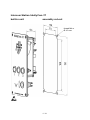
To gain access to the circuit board or the tamper alarm switch, unfasten the four
screws in the front panel.
Attention: Before opening or dismounting the device it has to be separated from
all voltage supply.
Concluding notes
CE (cable entry)
Protection rating CE
Connection cable
Wire and connector diameter
M20 x 1.5
IP66
Ø 5 to 9 mm
0.14 to 2.5 mm2
Only appropriate tools may be used for the assembly of the CE. The cable connection
is suitable for firmly secured conduits only. When locking the equipment, ensure tight
fit and cleanliness of all sealing. To retain the protection rating IP 66, cover screws
must be screwed in either side, diagonally with 1.4 Nm each.
Connection of the tamper alarm switch
Pull the control line through the cable gland of the box and connect the two wires to
the insulated screw joints of the tamper alarm switch. The voltage and the maximum
power in the tamper alarm circuit shall not exceed 60 VDC or 30 VAC respectively
30 W.
Connection of the telephone line
Pull the telephone line through the cable gland of the box and connect it to the
Terminal Connection Points TCP.
5 / 16