1
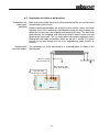
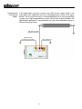
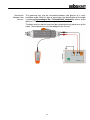
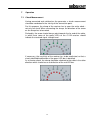
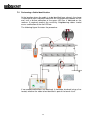
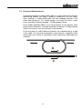
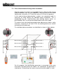
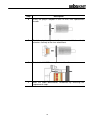
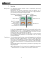
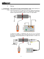
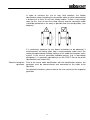
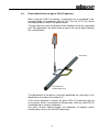
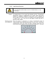
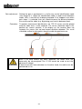
When measuring at the near end of the cable, the core carrying the test
current can then be easily identified by a deflection of the green LED bar
(provided the clamp is aligned in the direction as shown in the figure).
The technician there will then notify his colleague via radio of the
designation of the phase conductor showing the deflection. Subsequently,
this measurement is also to be carried out on the two other phase
conductors (with the clamp aligned in the same direction).
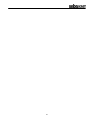
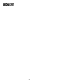
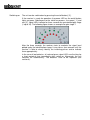
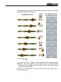
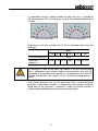
One of the conductors should not carry a signal while the other
measurement should result in a deflection of the red LED bar. In this way,
the two remaining phase conductors are identified one after the other. A
transposition is not possible.
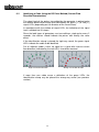
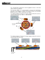
The phase position of the individual conductors to the far end is determined
using the same method.
It is important to note that in this test method, the short-circuiting and
earthing devices at both cable ends remain connected. They are
indispensable for this test method.
8
Charging the Accumulator (optional)
The accumulator is charged via the built-in charger. During the charging
process, the instrument should be switched off. The charging time is
automatically limited, i.e. when the accumulator is fully charged, the unit
switches over to trickle charge thus avoiding an overcharge.
The charging time is max. 6 hours and depends on the state of the
accumulator.
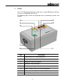
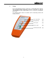
The power / battery status LED [ 6 ] indicates the status of the charging
process:
Yellow
Accumulator is charging
Green
Accumulator is fully charged
21