1
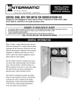
Tisch Environmental, Inc. OPERATIONS MANUAL TE-PUF Poly-Urethane Foam High Volume Air Sampler 145 South Miami Avenue Village of Cleves, Ohio 45002 Toll Free: TSP AND - PM10 (877) 263 - 7610 Direct: (513) 467-9000 FAX: (513) 467-9009 Web Site: Tisch-Env.com Email: [email protected] PREFACE Tisch Environmental, Inc. is a third generation family owned business. The owners Wilbur J. Tisch and James P. Tisch have been involved in the High Volume Air Pollution field for the last 20 years. Started in March of 1998, they would like to welcome you to their company. The intent of this manual is to instruct the user with unpacking, assembly, operating and calibration techniques. For information on air sampling principles, procedures and requirements please contact the local Environmental Protection Agency Office serving your area. CONTENTS Page Introduction …………………..................................................………..2 Unpacking and Assembly .………………………….......................... 3 Gabled Roof Assembly ……………………………………………….4 Electrical Hook-up ……………………………………………………5 Calibration Requirements ……………………..........................……….6 Calibration Procedure .......................................................……………..6 – 14 Unit Operation ..............................................…….............…………….15 Sorbents ………………………………………………………………16 Determination of Flow Rate …………………………………………..17 Maintenance ....................................................................……………….18 1 INTRODUCTION TE-PUF Poly-Urethane Foam sampler is a complete system designed to simultaneously collect suspended airborne particulates as well as trap airborne pesticide vapors at flow rates up to 280 liters per minute. The TE-PUF features the latest in technological advances for accurately measuring airborne particulates and vapors. 1. Samples semivolatile organic compounds. 2. Especially designed for sampling airbourne particulates and vapor contamination from pesticide compounds. 3. Successfully demonstrated to efficiently collect a number of organochlorine and organophosphate pesticides. 4. By-pass blower motor design permits continuous sampling for extended periods at rates to 280 liters per minute. 5. Proven sampler components housed in an anodized aluminum shelter for outdoor service. 6. Samples in accordance with U.S. EPA Method TO-4, “ Method for the Determination of Organochlorine Pesticides and Polychlorinated Biphenyls in Ambient Air “. A dual chambered aluminum sampling module contains both filtering systems. The upper chamber supports the airborne particulate filter media in a circular filter holder. The lower chamber encapsulates a glass cartridge which contains the PolyUrethane Foam for vapor entrapment. A wide variety of sorbents can be used in a manner that permits their continual use. Poly urethane foam or wet/dry granular solid media can be used individually or in combination.The dual chambered sampling module is designed for easy access to both upper and lower media. The threaded lower canister is removed with the cartridge intact for immediate exchange. Filter support screens and module components are equipped with gaskets providing a leak proof seal during the sampling process. Air flow rates are infinitely variable up to 280 liters per minute. The voltage variator adjusting screw alters the blower motor speed to achieve the flow rate desired. Air flow rate is measured through the flow venturi utilizing a 0-100" Magnehelic Gage. Periodic calibration is necessary to maintain on-site sampling accuracy. A Seven Day Mechanical Timer (TE-5007) is included as standard equipment and permits weekly scheduling with individual settings for each day and 14 trippers to turn the sampler On and Off as desired. Any day or days may be omitted. Day and night periods are distinctly marked. Other timers and programmers are available optionally to suit any sampling requirement. 2 UNPACKING 1. Shelter Box - 46" x 20" x 22" 70 lbs TE-1001 TE-5007 TE-1003 TE-5010 TE-1004 TE-1002 TE-1023 TE-1005 2. Lid Box PUF Anodized Aluminum Shelter 7-Day Mechanical Timer Flow Venturi & Calibration Valve Motor Voltage Control PUF Blower Motor Assembly Dual Sampling Module Exhaust Hose Magnehelic Gauge - 19" x 14" x 14" 9 lbs TE-5001-10 Gabled Roof *** Save the shipping containers and packing material for future use. ASSEMBLY: a. Open shelter box and remove Anodized Aluminum Shelter. b. Inside of shelter is the exhaust hose. Unwrap and insert end with speed clamp on end of blower motor discharge. Tighten with a flat edge screwdriver and put end of hose down wind of sampler. c. Enclosed in the 13" x 10" x 7" box on bottom of shelter is the TE-1002 Dual Sampling Module. Remove from box. d. Take out rubber plug that is in quick disconnect on shelter. Insert Dual Sampling Module and lock in place by pushing rings down for a tight seal. e. Take off cover that is on top of 4” filter holder. Turning motor on with cover in place will damage motor. f. Open lid box and remove 5001-10 Roof. 3 Gabled Roof ASSEMBLY Lid parts bag contents (taped inside of lid): 5 pcs 5 pcs 1 pc 1 pc 1 pc 1 pc 1 pc 1 pc 10-24 x 1/2 pan head screws 10-24 stop nuts 6-32 x 3/8 pan head screw 6-32 hex nut 20" chain with “S” hook TE-5001-10-9 roof back catch TE-5001-10-10 front catch TE-5001-10-11 rear lid hasp 1. Secure TE-5001-10-10 front catch to the shelter using 2 10-24 pan head screws with stop nuts. 2. Secure TE-5001-10-9 roof back catch to the back of shelter using 10-24 pan head screw with stop nut. 3. Secure TE-5001-10-11 rear lid hasp inside the lid with the slotted end angled up using 2 10-24 pan head screws with stop nuts. Note: These three items may need adjustment after the shelter lid is installed. 4. Remove 4 - 10-24 x 1/2 pan head screws from the nutserts in back of shelter. 5. Attach the lid to the shelter by placing the lid hinge plates on the "OUTSIDE" of the shelter top and tighten the 4 - 10-24 x 1/2 pan head screws into the nutserts. 6. Adjust the front catch to be sure that the lid slot lowers over it when closing the lid. The rear lid hasp should align with the roof back catch when the lid is open. 7. Attach the chain and "S" hook assembly to the side of the shelter with a 6-32 pan head screw and nut. 8. The lid can now be secured in an open or closed position with the "S" hook. 4 ELECTRICAL HOOK-UP TE-1004 PUF Blower Motor TE-5007 7-Day Mechanical Timer TE-5010 Motor Voltage Control ETI M F M F F M line voltage The TE-1004 PUF Blower Motor male cord set plugs into the TE-5010 Motor Voltage Control Female cord set. The male cord set of the Motor Voltage Control plugs into the TE-5007 7-Day Mechanical Timer timed female cord set which is on the left side of timer. The other female cord set on timer (on the right) is hot all the time and is an extra plug. The male cord set of timer plugs into the line voltage. 5 CALIBRATION REQUIREMENTS for TE-PUF Sampler The TE-PUF Sampler should be calibrated: 1. Upon installation 2. After motor maintenance 3. At least once every three months 4. After 360 sampling hours CALIBRATION PROCEDURE Step 1: Calibration of the PUF Sampler is performed without a foam plug (TE-1010) or filter paper in the sampling module. However the empty glass cartridge must remain in the module to insure a good seal through the module. Step 2: Install the TE-5040A Calibrator (orifice) on top of the 4" Filter Holder. Tighten and make sure of no leaks. Step 3: Open both ports on top of manometer and connect tubing from manometer port to the pressure tap on the TE-5040A Calibrator. Leave the opposite side of manometer port open to the atmosphere. Step 4: Open ball valve fully (handle should be straight up), this is located inside of shelter directly above the blower motor. Step 5: Turn the system on by tripping the manual switch on the timer. Allow a few minutes for motor to warm-up. Step 6: Adjust and tighten the voltage control screw (variac) on the TE-5010 to obtain a reading of 70 inches on the dial of the Magnehelic Gage (or 80 whatever is desired). Do not change until completion of calibration. Step 7: With 70 inches on the gage as your first calibration point, record this figure and the orifice manometer reading on your data sheet. To read a manometer one side goes up and one goes down, add both sides together, this is your inches of water. Step 8: Close the ball valve slightly to readjust the dial gage down to 60 inches. Record this figure and the orifice manometer reading on your data sheet. Step 9: Using the above procedure, adjust the ball valve for readings at 50, 40, and 30 inches and record on data sheet. You should have 5 sets of numbers 10 numbers in all. Step 10: Manually turn sampler off. 6 An example of a TE-PUF Sampler Calibration Data Sheet has been attached with data filled in from a typical calibration. This includes the transfer standard orifice calibration relationship which was taken from the Orifice Calibration Worksheet that accompanies the calibrator orifice. Since this calibration is for a PUF sampler, the slope and intercept for this orifice uses standard flows rather than actual flows. The five orifice manometer readings taken during the calibration have been recorded in the column on the data worksheet titled H2O (in). The five Magnehelic Gage readings taken during the calibration have been recorded under the column titled FLOW (magn). The orifice manometer readings need to be converted to the standard air flows they represent using the following equation: Qstd = 1/m[Sqrt((H20)(Pa/760)(298/Ta))-b] where: Qstd = actual flow rate as indicated by the calibrator orifice, m3/min H20 = orifice manometer reading during calibration, in. H20 Ta = ambient temperature during calibration, K ( K = 273 + °C) 298 = standard temperature, a constant that never changes, K Pa = ambient barometric pressure during calibration, mm Hg 760 = standard barometric pressure, a constant that never changes, mm Hg m = Qstandard slope of orifice calibration relationship b = Qstandard intercept of orifice calibration relationship. Once these standard flow rates have been determined for each of the five run points, they are recorded in the column titled Qstd, and are represented in cubic meters per minute. The Magnehelic Gage readings taken during the calibration need to be corrected to the current meteorological conditions using the following equation: FLOW (corrected) = Sqrt((magn)(Pa/760)(298/Ta)) where: FLOW (corrected) = Magnehelic Gage readings corrected to current Ta and Pa magn = Magnehelic Gage readings during calibration Pa = ambient barometric pressure during calibration, mm Hg 760 = standard barometric pressure, a constant, mm Hg Ta = ambient temperature during calibration, K ( K = 273 + °C) 298 = standard temperature, a constant, K After each of the Magnehelic Gage readings have been corrected, they are recorded in the column titled FLOW (corrected). 7 Using Qstd and FLOW (corrected) as the x and y axis respectively, a slope, intercept, and correlation coefficient can be calculated using the least squares regression method. The correlation coefficient should never be less than 0.990 after a five point calibration. A coefficient below .990 indicates a calibration that is not linear and the calibration should be performed again. If this occurs, it is most likely the result of an air leak during the calibration. The equations for determining the slope (m) and intercept (b) are as follows: ( ∑ x)( ∑ y) ∑ xy - n m = ( ∑ x )2 ∑ x2 where: - ; b = y - mx n n = number of observations y = Σy/n; x = Σx/n Σ = sum of. The equation for the coefficient of correlation (r) is as follows: ( ∑ x)( ∑ y) r = ∑ xy 2 ∑ x where: - n (∑ x) 2 n ∑ y 2 (∑ y) n 2 n = number of observations Σ = sum of If you wanted to set this sampler at .242 m3/min (8.5 CFM or 242 LPM) (Make sure the ball valve is open fully, a 4" filter is in place, and the module is loaded) you would turn the voltage control screw or variac until the Magnehelic Gage read 60 inches. By making sure that the sampler is operating at a Magnehelic Gage reading that is within the acceptable range, it can be assumed that valid PUF data is being collected. 8 Example Problems The following example problems use data from the attached calibration worksheet. After all the sampling site information, calibrator information, and meteorological information have been recorded on the worksheet, standard air flows need to be determined from the orifice manometer readings taken during the calibration using the following equation: 1. Qstd = 1/m[Sqrt((H20)(Pa/760)(298/Ta))-b] where: Qstd = actual flow rate as indicated by the calibrator orifice, m3/min H20 = orifice manometer reading during calibration, in. H20 Ta = ambient temperature during calibration, K ( K = 273 + °C) 298 = standard temperature, a constant that never changes, K Pa = ambient barometric pressure during calibration, mm Hg 760 = standard barometric pressure, a constant that never changes, mm Hg m = Qstandard slope of orifice calibration relationship b = Qstandard intercept of orifice calibration relationship. Note that the ambient temperature is needed in degrees Kelvin to satisfy the Qstd equation. Also, the barometric pressure needs to be reported in millimeters of mercury. In our case the two following conversions may be needed: 2. degrees Kelvin = [5/9 (degrees Fahrenheit - 32)] + 273 3. millimeters of mercury = 25.4(inches of H2O/13.6) Inserting the numbers from the calibration worksheet run point number one we get: 4. 5. Qstd = 1/10.19[Sqrt((8.2)(635/760)(298/295)) - (-.03523)] Qstd = .098[Sqrt((8.2)(.836)(1.01)) + .03523] 6. Qstd = .098[Sqrt(6.924) + .03523] 7. Qstd = .098[2.631 + .03523] 8. Qstd = .098[2.666] 9. Qstd = .261 Throughout these example problems you may find that your answers vary some from those arrived at here. This is probably due to different calculators carrying numbers to different decimal points. The variations are usually slight and should not be a point of concern. 9 With the Qstd determined, the corrected Magnehelic Gage reading FLOW (corrected) for this run point needs to be calculated using the following equation: 10. FLOW (corrected) = Sqrt((magn)(Pa/760)(298/Ta)) where: FLOW (corrected) = Magnehelic Gage readings corrected to standard magn = Magnehelic Gage readings during calibration Pa = ambient barometric pressure during calibration, mm Hg. 760 = standard barometric pressure, mm Hg Ta = ambient temperature during calibration, K ( K = 273 + °C) 298 = standard temperature, K. Inserting the data from run point one on the calibration worksheet we get: 11. FLOW (corrected) = Sqrt((70)(635/760)(298/295)) 12. FLOW (corrected) = Sqrt((70)(.836)(1.01)) 13. FLOW (corrected) = Sqrt(59.105) 14. FLOW (corrected) = 7.69 This procedure should be completed for all five run points. Using Qstd as our x-axis, and FLOW (corrected) as our y-axis, a slope, intercept, and correlation coefficient can be determined using the least squares regression method. The equations for determining the slope (m) and intercept (b) are as follows: ( ∑ x)( ∑ y) ∑ xy 15. - m= ( ∑ x )2 ∑ x2 where: n - n = number of observations y = Σy/n; x = Σx/n Σ = sum of. 10 n ; b = y - mx The equation for the coefficient of correlation (r) is as follows: ( ∑ x)( ∑ y) 16. ∑ xy - r = n ( ) ( ) 2 2 ∑ ∑ x y 2 y2 ∑ ∑ x n n where: n = number of observations Σ = sum of Before these can be determined, some preliminary algebra is necessary. Σx, Σy, Σx2, Σxy, (Σx)2, (Σy)2, n, , and 17. 18. 19. 20. 21. 22. 23. 24. 25. 26. need to be determined. Σx Σy Σx2 Σy2 Σxy = .262 + .242 + .223 + .198 + .175 = 1.1 = 7.69 + 7.12 + 6.50 + 5.81 + 5.03 = 32.15 = (.262)2 + (.242)2 + (.223)2 + (.198)2 + (.175)2 = .246766 = (7.69)2 + (7.12)2 + (6.50)2 + (5.81)2 + (5.03)2 = 211.1375 = (.262)(7.69) + (.242)(7.12) + (.223)(6.5) + (.198)(5.81) + (.175)(5.03) = 7.21795 n =5 = Σx/n = .22 = Σy/n = 6.43 (Σx)2 = (1.1)2 = 1.21 (Σy)2 = (32.15)2 = 1033.6225 Inserting the numbers: 27. slope = (1.1)(32.15) 7.21795 5 1.21 .246766 5 (35.365) 5 1.21 46766 5 7.21795 28. slope = 29. slope = 30. 31. slope = slope = 7.21795 - 7.073 .246766 - .242 .14495 .004766 30.41 11 32. intercept = 33. intercept = 34. intercept = 6.43 - (30.41)(.22) 6.43 - 6.69 -0.26 (1.1)(32.15) 35. correlation coeff. 7.21795 - = 5 2 2 ( ( 1.1) 32.15) .246766 211.1375 5 5 (35.365) 36. correlation coeff. = 7.21795 - 5 [(.246766 - .242)] [(211.1375 - 206.7245)] 37. correlation coeff. = 38. correlation coeff. = 39. correlation coeff. = 40. correlation coeff. = 41. correlation coeff. = (7.21795 - 7.073) [(.246766 - .242)][(211.1375 - 206.7245)] .14495 (.004766)(4.413) .14495 .0210323 .14495 .1450251 .999 A calibration that has a correlation coefficient of less than .990 is not considered linear and should be re-calibrated. Since the correlation coeff. is > .990 , we have a good calibration. 12 UNIT OPERATION 1. The PUF Sampler may be operated at ground level or on roof tops. In urban or congested areas, it is recommended that the sampler be placed on the roof of a single story building. The sampler should be located in an unobstructed area, at least two meters from any obstacle to air flow. The exhaust hose should be stretched out in a down wind direction if possible. 2. The sampler should be operated for 24 hours in order to obtain average daily levels of airborne pesticides. 3. On and off times and weather conditions during sampling periods should be recorded. Air concentrations may fluctuate with time of day, temperature, humidity, wind direction and velocity and other climatological conditions. 4. Magnehelic Gage readings should be taken at the beginning and end of each sampling period to obtain an average magnehelic gage reading. 5. Blower motor brushes should be inspected frequently and replaced before expending. An electrical source of 110 volts, 15 amps is required. SAMPLING MODULE 1. Release the three (3) swing bolts on the 4" filter holder (FH-2104) and remove the triangle cover (cover must be off when sampler is "ON") and hold down ring. 2. Install a clean 102mm dia. glass fiber filter on the support screen in between the teflon gaskets and secure it with the hold down ring and swing bolts. 3. Unscrew together the 4" filter holder and the sampling module cap leaving the module tube in place with the glass cartridge exposed. 4. Load the glass cartridge with foam and or foam/granular solids and replace in the module tube. Fasten the glass cartridge with the module cap and 4" filter holder assembly while making sure that the module assembly, 4" filter holder and all fittings are snug. 5. The glass cartridge and glass fiber filter should be removed from the sampler with forceps and clean gloved hands and immediately placed in a sealed container for transport to the laboratory. Similar care should be taken to prevent contamination of the filter paper and vapor trap (foam) when loading the sampler. 6. It is recommended to have two (2) sampling modules for each sampling system so that filter and foam exchange can take place in the laboratory. 15 DESCRIPTIONS OF SAMPLING MEDIA (SORBENTS) 1. Two types of sampling media are recommended for use with the PUF Sampler: polyurethane foams and granular solid sorbents. Foams may be used separately or in combination with granular solids. The sorbent may be extracted and reused (after drying) without unloading the cartridge. 2. Polyurethane Foam (PUF): Part number TE-1010 three inch plug is recommended. Also available are two inch (TE-1011) and one inch (TE-1012). This type of foam is white and yellows on exposure to light. Color does not effect the collection efficiency of the material. 3. Granular Solids: a. Porous (macroreticular) chromatography sorbents recommended. Pore sizes and mesh sizes must be selected to permit air flow rates of at least 200 liters/minute. Approximately 25 cm3 of sorbent is recommended. The granular solids may be sandwiched between two layers of foam to prevent loss during sampling and extraction. 16 DETERMINATION OF FLOW RATE To figure out the total volume of air that flowed through the PUF sampler during your sampling run take a set-up magnehelic gage reading (when you set the sampler up manually turn it on and take a magnehelic gage reading; in our example it should be 60 inches) and a pick-up reading (after the sample has been taken again manually turn sampler on and take a magnehelic gage reading; for our example let's say it read 54 inches). Take 60 + 54 = 114 114/2 = 57 so the magnehelic gage reading you would use is 57 inches. Put that into the formula (on bottom of worksheet): 1/m([Sqrt(magn)(Pav/760)(298/Tav)]- b) m b magn Tav Pav Sqrt = sampler slope = sampler intercept = average magnehelic gage reading = daily average temperature = daily average pressure = square root Example: m3/min = 1/30.278([Sqrt(57)(727/760)(298/295)]-(-.2293)) m3/min = .033 ([Sqrt(57)(.957)(1.01)] + .2293) m3/min = .033 ([Sqrt(55.094)] + .2293) m3/min = .033 ([(7.423)] + .2293) m3/min = .033 (7.423 + .2293) m3/min = .033 (7.652) m3/min = .253 lpm = 253 Total liters of air = lpm x 60 x hours that sampler ran Let's say our sampler ran 23.3 hours (end ETI reading - start ETI reading) ** Make sure ETI is in hours otherwise convert to hours ** Total liters of air = 253 x 60 x 23.3 = 353,694 liters of air 17 MAINTENANCE A regular maintenance schedule will allow a monitoring network to operate for longer periods of time without system failure. Our customers may find the adjustments in routine maintenance frequencies are necessary due to the operational demands on their sampler(s). We recommend that the following cleaning and maintenance activities be observed until a stable operating history of the sampler has been established. TE-PUF Sampler The TE-PUF sampler should be routinely inspected and maintained as follows: 1. Power cords should be checked for crimps, cracks or exposed junctions each sample day. Do not allow power cords or outlets to be immersed in water; if necessary raise the cords above the ground by taping them to the shelter legs. 2. Inspect the TE-1002 Dual Sampling Module. a. Make sure all gaskets are sealing properly; replace if necessary. b. Clean any dirt that is built up around the module and filter holder. c. Make sure quick disconnect is working correctly by making a good seal. TE-1004 Blower Motor Assembly 1. The motor assembly is durable and has a long life if maintained properly. The routine maintenance required is: a. Inspecting and replacing the motor flange gasket and motor cushion routinely. b. Replacing the motor TE-33384 carbon brushes every 400 to 500 hours of operation. It is imperative that the brushes be replaced before the brush shunt touches the motor commutator. Totally expended brushes greatly reduce motor life!! 18 MOTOR BRUSH REPLACEMENT Model TE-PUF Sampler–Brush part #TE-33384 (220volt Brush part #TE-33378) CAUTION: Ensure that all electrical power to the TE-PUF Sampler is disconnected prior to opening the motor housing. Unplug the motor power cord. 1. Remove the Motor Mounting Cover by removing the four bolts. This will expose the flange gasket and the motor. Turn motor over. 2. Remove ground wires from backplate and carefully lift the metal housing from the motor. 3. With a screwdriver carefully remove the plastic fan cover by prying in between brush and cover until both sides pop loose. 4. With a screwdriver carefully pry the brass quick disconnect tabs away from the expended brushes. 5. With a screwdriver remove brush holder and release TE-33384 brushes. 6. With new TE-33384 brushes, carefully slide quick disconnect tabs firmly into tab slot until seated. 7. Push brush carbon against commutator until plastic brush housing falls into place on commutator end bracket. 8. Replace brush holder clamps onto brushes. 9. Assemble motor after brush replacement: snap plastic fan cover back into place, feed ground wires back through backplate, put housing back on to motor, pull cord set back to normal postion, ** Make sure wires do not get smashed between metal ring and housing! ** fasten ground wires to backplate, turn motor over, tighten flange on top of housing and gasket. **WARNING** Change Brushes Before Brush Shunt Touches Commutator !! MOTOR BRUSH SEATING PROCEDURE CAUTION: Direct application of full voltage after changing brushes will cause arcing, commutator pitting, and reduce overall life. To achieve best performance from new TE-33384 brushes they must be seated on the commutator before full voltage is applied. After brush change apply 50% voltage for fifteen to twenty minutes to accomplish this seating. Use of TE-5010 Flow Selector on system provides the reduced voltage for brush seating. 19