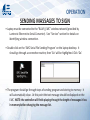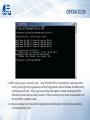
1
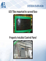
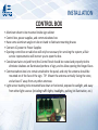
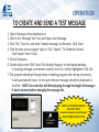
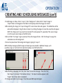
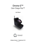
Blair Companies
Electronic Message Center
(EMC)
CERTIFICATION TRAINING LESSON
Revision 2
Please refer to full installation instructions available at
www.blaircompanies.com/ledsupport
SYSTEM OVERVIEW
LED Tiles mounted to curved face
Properly Installed Control Panel
SYSTEM OVERVIEW
A
C
B
E
D
H
20 watt
20 watt
Controller
and Driver
Communications
system
I
J
A—Laptop
B—Engenious
C—LED Tile
F
D—240W Power Supply
E—20W Power Supply
F—Control Board
G
G—Driver Board
H—Ethernet to serial
Converter (Engenious)
I—Control Board
J—Tempature Probe
SYSTEM OVERVIEW
• Laptop will be located inside the store. The Lantronix Ethernet-to-Serial Converter provides
the secure “BLAIR_EMC” wireless network.
• Control Panel is to be mounted inside sign; it is the support for the control system,
power supplies, and communications box.
• Each 240W 12V power supply provides power to (8) monochrome or (12) color tiles via
a 6’ power cable.
• Controller Board connects to the Lantronix Ethernet-to-Serial Converter with a Cat5 cable
with DB9 adapters.
• Controller Board and Driver Board connect together via ribbon cable (inside waterproof box).
• Data is communicated via daisy chains of up to (5) LED tiles (monochrome) and (16) LED tiles
(RGB) from the Driver Board using the supplied cables.
• When faces are shipped separately from the control system (such is the case with a retrofit),
the data cables will be labeled A1, B1, etc as required.
• Designation of A, B, C, etc is left to right first, then top to bottom (facing the sign) in blocks
of UP TO 5 or 16 tiles (monochrome / RGB respectively):
A-for each face will be the top left tile (facing the sign); daisy chain will be the rest of the string of 5 or 16 tiles,
if there are that many
B-for each face will be the 6th or 17th tile of first row for a matrix more than 5monochrome or 16 RGB tiles wide;
otherwise B would be leftmost tile of second row for a matrix 5 monochrome or 16 RGB tiles wide or less
C-for each face will be 11th tile of first row for a single row matrix more than 10 tiles wide; otherwise C would
be leftmost tile of second row for a double row matrix
• For a double faced sign, the same pattern of A, B, C, etc is used on each face
INSTALLATION
INSTALLATION
SAFETY FIRST!
• Wear all appropriate personal protective gear
• Make appropriate arrangements with store owner/manager prior to visit
• Inform store personnel upon arrival
• Disconnect electrical power (Using Lock-out Tag-out) before opening sign
• Barricade area safely for bystanders and traffic
*Any work done on BP/ARCO sites requires all workers to be API WorkSafe certified. Contact your Blair account manager for details*
CHECK MATERIALS
• Ensure all components are not damaged within 24 hours
of receiving them
• Have all necessary tools on site including repair kit
• Have all barricades, cones, caution tape, and warning
signs required to secure the work area
INSTALLATION
ELECTRICAL REQUIREMENTS
• Dedicated 20A circuits for EMC system
• 100V-240VAC for Power Supply
• Timers and energy management systems must be
disabled for these circuits
• Use UL listed conduit for all AC wiring runs
• Minimum electrical grounding is a dedicated ½” x 8’ copper
grounding rod, and a #8 copper grounding electrode terminated
to the ground wire of the AC supply line and sign base. This is
supplied by the installer.
INSTALLATION
CONTROL BOX
• Aluminum sheet to be mounted inside sign cabinet
• Control box, power supplies, and communications box
• Have some aluminum angle or tube on hand to fabricate mounting braces
• Connect AC power to Power Supplies
• Opening control box or radio box will only be necessary for servicing the system; a Blair
service representative will instruct you to open the box.
• Conduit and wires to (and from) the Control Panel should be routed and properly tied to
eliminate shadows on illuminated portions of sign, and to allow opening the hinged faces
• Communications box is to remain attached to the panel, and only the antenna should be
mounted on of the face of the sign. TIP: Mount the antenna vertically facing the store,
and at least 5’ away from any other antennae.
• Light sensor bushing to be mounted face down or horizontal, exposed to sunlight, and away
from other light sources (including traffic lights, headlights, parking lot illumination, etc.)
INSTALLATION
LED Tiles
• Monochrome pixel count 16Hx18W; Color pixel count 13Hx15W
• Blair will supply pattern for mounting tiles for retrofit signs
• For retrofit, black vinyl background will also be provided
• Drill 17/64” holes to mount 6-32 rivet nuts/”nutserts” (provided)
• Drill holes for cables as shown on pattern
• Installer must supply rivet nut/”nutsert” tool
• Attach tiles with supplied 6-32 Screws. DO NOT use an electric drill to tighten screws.
• Handle tiles carefully to avoid damaging LEDs
TILE CONNECTIONS
• Power plug(s) attached to power supply cables, provide power to tile.
• One data cable provided for every block of up to 5 tiles monochrome
16 tiles RGB as labeled (see SYSTEM OVERVIEW for a detailed description)
• Daisy chain power and data connection between tiles; data always flows from
left to right (when viewed from front) in same row; power can daisy chain
across rows and/or columns
• Put drip loop in each cable to prevent water from running to back of LED tiles
• Use supplied cable tie down on back of plastic ring (if so equipped) to secure cables.
• If no tie down is provided, ensure cables are tightly secured in place
• Data termination plug will be provided for the last tile of each set’s data OUT port (only RGB).
INSTALLATION
COMMUNICATION METHODS
• Standard communication is WiFi connection from laptop to Engenious.
• WiFi signal from store to sign should be as unobstructed as possible with line
of sight to sign
• Locate laptop close to front of building on side where sign is, in a window if possible
• For distances less than 300’ (total cable length), CAT5 cable can be used between
the computer and the sign
• CAT5 connection will still utilize the Lantronix Ethernet-to-serial module
• For longer distances where direct connection is required, fiber optic cable is used to
connect computer and the sign
• Fiber specifications are 1300nm, 62.5/125 grade, with ST terminations
• Ethernet to fiber media converters are required at each end of the fiber; these will be
included when ordered as a fiber communication setup
INSTALLATION
Communication (Sign Side)
• Communications box is permanently attached to Control Panel.
• Antenna to be mounted OUTSIDE OF SIGN with line-of-sight to store
(Recommended to be placed on the black vinyl of the sign face.)
• Antenna is to be vertical
COMMUNICATION (store side)
• Unpack laptop; connect laptop battery and plug in included power supply.
• Laptop should be mounted as close to the front of the store as possible,
with clearest line-of-sight to sign
TESTING SYSTEM
• Check all connections
• Apply power to sign
• Create and send test message (see Operation)
• Check that all LEDs light on each face, and the message is displaying properly
OPERATION
TO CREATE AND SEND A TEST MESSAGE
1. Open Colorspace from desktop icon.
2. Click in the ‘Message Text’ box, and type a test message.
3. Click ‘File’, ‘Save As’, and enter ‘Sample message’ as filename. Click ‘Save’.
4. Click the blue arrow at upper right or ‘File’, ‘Export’, ‘To Scheduler Library’.
Click ‘Export’ then ‘Close’.
5. Close Colorspace.
6. Double click on the ‘EMC Serial File Sending Program’ on the laptop desktop.
It should go through a connection routine, then ‘Go’ will be highlighted. Click ‘Go’.
7. The program should go through steps of sending program and storing to memory.
It will automatically close. At this point the test message should be displayed on
the EMC. NOTE: the controller will finish playing through the length of messages
it has in memory before changing the message list.
REFER TO COLORSPACE MANUAL
ON LAPTOP OR AT
www.blaircompanies.com/ledsupport
FOR SOFTWARE INSTRUCTIONS
OPERATION
CREATING AND SCHEDULING MESSAGES
Refer to Colorspace Manual for detailed instructions on utilizing EMC. A copy of the Manual
is on the laptop, as well as being available at www.blaircompanies.com/ledsupport
• Messages are created in Colorspace. Different fonts and sizes, colors, and effects such as
Bold and Italic are available.
• Load and Exit effects are animations for how the message appears and exits the EMC
• Layer 1 is always either a background (image or video) and/or the overall length of a message.
A message can have multiple text layers contained in it, either overlapping or subsequent.
Each layer can have unique text.
• Click ‘Layer’ then ‘Create Layer’ to add layer. Options are available to make new layers begin
after previous layer. Layers can overlap in time allowing text to appear at different times.
• The Layer bar shows each message length in frames and seconds. Click on the end of the bar
to drag it out to the right to lengthen a message, or double click on the time in seconds.
• Click ‘View’ then ‘Play Message’ to get a
preview of the message.
• The example shown here will show “ABC”
then “123” for 3 seconds each
In photo ‘Message Text’ box, select ‘Ticker’
to create scrolling message. Right click on
‘Layer 2’ and select ‘Ticker Timing’ to change
scrolling speed of message.
OPERATION
CREATING AND SCHEDULING MESSAGES (con’t)
• To add images or video, click on ‘Layer 1’, then ‘Background’. Select either ‘Import Image’ or
‘Import Video’ and navigate to the folder on the laptop where the images are stored.
• After selecting the image, the “Layer 1:Image Fill” screen shown here will appear. The dotted box will be
what will be displayed. Drag the box to locate it, and drag the edges to resize the area that will appear.
NOTE: the ‘Shape Lock’ may need to be turned off to allow proper fit, especially if the source image
is not the exact same shape as the EMC matrix.
• Click and hold ‘Try Image’ to get a preview of how the image will look. Click ‘Set Image’ to assign the
selected area as the background.
• Text can be placed over the background image by typing to ‘Layer 2’.
NOTE: Holiday messages of both image and video type are provided. Additional images, such
as photos, logos, etc will need to be placed on laptop via a USB thumb drive.
• After finishing a message, click ‘File’, then ‘Save’ to save the message. Then click ‘File’,
then ‘Export’ and select ‘To Scheduler Library’. The Export window appears; click
‘Export’ then ‘Close’ when completed.
• If changes are made to a message, it must be saved AND exported again.
OPERATION
CREATING AND SCHEDULING MESSAGES (con’t)
• The Scheduler program allows playing messages at different times of the day. By default, when a
message is exported in Colorspace, it will play all the time. If multiple messages are scheduled at the
same time, they will play one after the other then repeat.
• The ‘Message Files’ tab shows all exported messages. If they are active, the check box to the left will be
checked, and the message will be shown on the calendar view in the large window.
• To set a message timing, click on the ‘None’ at one of the Time Limits. The ‘Select Time Limit Start’ box
will appear. Select a start time for the message and click ‘OK’. That Time Limit will then show
“xx:xx AM/PM –12:00AM”. Click on the ’12:00AM’ and the ‘Select Time Limit End’ box will appear.
Select an ending time for the message.
• Up to 4 Time Limits can be set for each message. The Calendar view will provide a diagram of times a
message is scheduled to play.
• ‘Date Range’ can be set to begin playing and cease
playing a message on a certain date. This can be
done for months in advance.
• ‘Sequencer’ tab shows the order messages will play in.
Click and drag messages up or down in the list to
rearrange the play order.
• The sign will get its time information each time the
schedule is sent. The laptop clock will need to be
properly set for correct time to be sent to sign.
Computer clock is in lower right of desktop. Double
click to open clock, set to proper time, and click
“OK” to close.
OPERATION
SENDING MASSAGES TO SIGN
• Laptop must be connected to the “BLAIR_EMC” wireless network (provided by
Lantronix Ethernet-to-Serial Converter). See “Service” section for details on
identifying wireless connection.
• Double click on the ‘EMC Serial File Sending Program’ on the laptop desktop. It
should go through a connection routine, then ‘Go’ will be highlighted. Click ‘Go’.
• The program should go through steps of sending program and storing to memory. It
will automatically close. At this point the test message should be displayed on the
EMC. NOTE: the controller will finish playing through the length of messages it has
in memory before changing the message list.
OPERATION
CUSTOMER TRAINING
• Train customer on operation: ensuring wireless network connection, creating
messages, scheduling, and using the sending program
• Electronic copy of User Manual is on laptop desktop
Satisfy all their questions and concerns
• Show them Blair contacts for service issues in back of Operation Manual
• Have customer contact Blair with any service issues
SITE WRAP UP
• Take completion photos of each major part of installation: Faces in operation
(close up and 5x height away from sign), Radio mounting at sign, Laptop location
in store, top of sign (showing sealed) taken from inside, back of each face showing
cable connections, Control Box mounting.
• Complete Warranty Card and return to your Blair Contact along with completion
photos within 30 days.
OPERATION
SERVICE
Service Manager
Kim Kurtz
(814) 283-2037
[email protected]
BLAIR 24 HOUR EMERGENCY SERVICE
800-563-9598
OPERATION
PING TEST
TO CHECK COMMUNICATION BETWEEN THE LAPTOP AND SIGN
1. Verify that the sign and wifi router are powered and connected properly. Laptop should
be connected to “BLAIR_EMC” wireless network (Go to Start Menu, ‘Settings’, then
‘Control Panel’, then ‘Network Connections’, then ‘Wireless Network Connection’.
There may also be a wireless icon in lower right that shows what network is connected
2.Go to the laptop Windows Start Menu, click on ‘Programs’, then ‘Accessories’, then
‘Command Prompt’. Type: “ping 192.168.1.1” (no quotations) and press enter. It will go
through the ping request, and the Ping statistics should indicate 4 Packets sent, 4 received,
and 0 lost. If the ping is successful, the laptop is communicating with the router. If files
cannot be sent, check all connections on the router.
OPERATION
3. After router ping is successful, type: “ping 192.168.1.99” (no quotations) and press enter.
It will go through the ping request, and the Ping statistics should indicate 4 Packets sent,
4 received, and 0 lost. If the ping is successful, the laptop is communicating with the
Ethernet to Serial device (radio) receiver. If files cannot be sent, check all connections on
the controller—power & radio.
4. It may be necessary to relocate the laptop/router combination in the store to establish a
consistent wireless link.
CONTACTS
Blair Companies – Main Office
(800) 581-0708
[email protected]
Technical Services Manager
Hector Ortiz
(814) 283-2038
(814) 934-8662 Cell
[email protected]
Product Engineer
Matthew Barton
(814) 949-6419
[email protected]
Service Manager
Kim Kurtz
(814) 283-2037
[email protected]
National Installation Manager
Scott Hoffer
(814) 283-2036
(814) 935-8506 Cell
shoff[email protected]
Project Manager
Melinda McEldowney
(814) 283-2066
(814) 329-8080 Cell
[email protected]
Blair Companies 24 Hour Emergency Service
800-563-9598