1
3.
SYSTEM INSTALLATION
a.
b.
ST300-S/SM, VTR/DDR CONTROLLER
1)
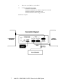
Plug one end of a 9-conductor, RS422 serial cable into the VTR 1 (2, 3 or 4)
connector on the rear of the ST300. Plug the other end of the cable into the
REMOTE connector on the Video Server.
2)
Connect the +5, +12, -12 VDC POWER SUPPLY into the POWER connector
on the rear of the ST300. Plug the Power Supply into an outlet, 90 VAC to 240
VAC.
3)
Connect the 9-pin connector on the supplied KBIO adapter to the VTR2
connector on the rear of the ST300.
4)
Connect a standard PS2 keyboard to the PS2 connector on the supplied KBIO
adapter.
5)
Check SETUP MENU prior to using the ST300 to confirm proper Record mode
and other User settable modes. See CONFIGURING THE PROFILE FOR
NATIVE MODE, Section 17.a.
PRODUCTION SWITCHER
1)
Connect a standard cable (RS422, 9-pin serial cable) to the “AUX” connector on
the rear of the ST300. Connect the other end of the cable to the Peripheral Bus
Connector on the production switcher. (Communication Format- 38.4K, N, 8,1)
2)
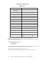
The ST300 has 4 Peripheral Device Addresses, one for each VTR that it
controls. To set the Device Address for each VTR:
3)
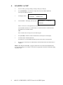
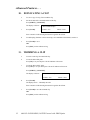
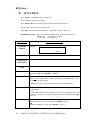
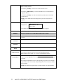
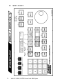
Press [MENU] on the ST300.
4)
Turn the Wheel clockwise until “Peripheral Address” is displayed.
5)
Press VTR[1], VTR[2], VTR[3] or VTR[4] to select a VTR.
6)
Assign a Peripheral Device Address for that VTR, from 0 to 23,by entering the
desired address using the numeric keypad.
Address 24 or greater will turn PBIO off.
7)
Select the next VTR, then assign a Peripheral Device Address for it from 0 to
23, by entering the desired address using the numeric keypad.
Each VTR must have its own unique address.
8)
6
To select a Production Switcher type (Default = Grass Valley Group).
a)
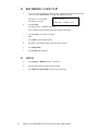
Press [MENU] on the ST300.
b)
Turn the Wheel until “SWITCHER’ is displayed.
c)
Press the Softkeys to toggle between Sony and Grass Valley types of
Production Switcher.
4000 CL-N-PBIO-KBIO, NATIVE Protocol with PBIO Option