1
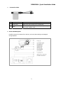
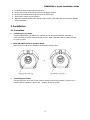
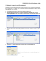
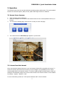
REHB0309-1, Quick Installation Guide 1. Description This manual applies to the REHB0309-1 network camera. The network Camera provides a network service for a progressive-scan image sensor that can be monitored on a real-time screen regardless of distance or location. By using its dedicated program, many users are able to access the Network Camera at once, or a single user can monitor various network cameras at the same time. It also enables users to play, store and retrieve a monitored image by using a PC. All the settings and real-time monitoring screens are also provided through web access. The Network Camera is fully featured for security surveillance and remote monitoring needs. It is based on a DSP compression chip, and makes it available on the network as real-time, full frame rate Motion JPEG and H.264 (or MPEG-4) video streams. The alarm input and alarm output can be used to connect various third party devices such as, door sensors and alarm bells. • Installation Steps Follow these steps to install the network camera on your local network (LAN): 1. 2. 3. 4. • Check the package contents against the list below. Connect the Network Camera. See page 3. Set an IP address. See page 6. Set the password. See page 8. Package Component The system comes with the following components: Camera unit • Installation CD Installation Guide Template Sheet Accessory Kit Contents in the installation CD 1. 2. 3. 4. 5. The The The The The REHB0309-1 User’s Manual SmartManager User’s Manual Revo Remote Pro HD User’s Manual SmartManager Installation software Revo Remote Pro HD Installation software Note: Check your package to make sure that you received the complete system, including all components shown above. REHB0309-1, Quick Installation Guide • Connection Cable NO Wire Color Description 1 Red: DC12V White: GND Main Power, 2pin terminal, DC12V 700mA(8.4W) 2 Black Ethernet, RJ-45 port compatible with 10/100Mbps having PoE functionality. Modular Jack Parts and Description Carefully remove the contents from the box, and verity that nothing was damaged during shipment. 2 REHB0309-1, Quick Installation Guide Camera Dimension See the diagrams below for the exact dimension of the REHB0309-1, IR Bullet network cameras. Dimensions Unit: mm Base Installation(Cable through the wall with the mount base) There are two ways of installing the camera. 3 REHB0309-1, Quick Installation Guide 1) Installation1 (Cable through the wall with the mount base) A. Drill the mounting location, using the template sheet (or the bottom of the mount base) as a template. B. Insert the plastic anchors into the hole which has just been drilled. C. Connect connection cable and network lines. D. Fit the screw holes of the mount base into the plastic anchors. E. Screw up the mount screws (M5x20). F. Adjust the camera suitably, and fasten the mount screws (M6x16) to fix the camera. 2) Installation 2 (Using the conduit knockout punched with Mount Base) A. Drill the mounting location, using the template sheet (or the bottom of the mount base) as a template. B. Insert the plastic anchors into the hole which has just been drilled. 4 REHB0309-1, Quick Installation Guide C. D. E. F. G. Connect connection cable and network lines. Fit the screw holes of the mount base into the plastic anchors. Remove the conduit knockout punched for the cable entry. Screw up the mount screws (M5x20). Adjust the camera suitably using the pan & tilt function, and fasten the mount screws (M6x16) to fix the camera. 2. Installation 2.1 Connection • Connecting to the RJ-45 Connect a standard RJ-45 cable to the network port of the network camera. Generally a cross-over cable is used to connect directly to a PC, while a standard cable is used to connect to a hub or router. Micro SD memory slot on the Rear Board Remove the rear cap of the camera to insert the SD memory card. • Connecting the Power Connect the power of DC12V for the network camera. Connect the positive(+) pole to the ‘+’ position and the negative(-) pole to the ‘-‘ position for the DC power. 5 REHB0309-1, Quick Installation Guide 2.2 Network Connection and IP assignment The Network Camera supports the operation through the network. When a camera is first connected to the network it has no IP address. So, it is necessary to allocate an IP address to the device with the “Smart Manager” utility on the CD. 1. 2. Connect the Network Camera / device to the network and power it up. Start SmartManager utility (Start>All programs>SmartManager>SmartManager), the main window will be displayed, after a short while any network devices connected to the network will be displayed in the list. 3. Select the camera on the list and click right button of the mouse. You can see the pop-up menu below. 4. Select Assign IP. You will see an Assign IP window. Enter the required IP address. Note: For more information, refer to the Smart Manager User’s Manual. 6 REHB0309-1, Quick Installation Guide 3. Operation The Network Camera can be used with Windows operating system and browsers. The recommended browsers are Internet Explorer, Safari, Firefox, Opera and Google Chrome for Windows. 3.1 Access from a browser 1. 2. 3. Start a browser (Internet Explorer). Enter the IP address or host name of the Network Camera in the Location/Address field of your browser. You can see the starting page. Click Live View or Setup to enter web page. 4. The network camera’s Live View page appears in your browser. 3.2. Access from the internet Once connected the Network Camera on your local network (LAN) will be accessible via internet. To access the network camera from the Internet you must configure your broadband router to allow incoming data traffic to the network camera. To do this, enable the NAT-traversal feature, which will attempt to automatically configure the router to allow access to the network camera. This is enabled from Setup > System > Network > NAT. For more information, please see “3.5.5 System>Network>NAT” of User’s Manual. 7 REHB0309-1, Quick Installation Guide 3.3 Setting the admin password over a secure connection To gain access to the product, the password for the administrator must be set. This is done in the “Admin Password” dialog, which is displayed when the network camera is accessed for setup the first time. Enter your admin name and password. Note: The default administrator username and password is “admin”. If the password is lost, the Network Camera must be reset to the factory default settings. See “3.6 Resetting to the Factory Default Settings”. 3.4 Live View Page The live view page comes in eight screen modes: 1920x1080, 1280x1024, 1280x720, 720x480(576), 640x480, 352x240(288) and 320x240. Users are allowed to select the most suitable one out of those modes. Please, adjust the mode in accordance with your PC specifications and monitoring purposes. 1) General controls Live View Page Search & Playback Page Setup Page Help Page The video drop-down list allows you to select a customized or pre-programmed video stream on the live view page. Stream profiles are configured under Setup > Basic Configuration > Video & Image. For more information, please see “3.5.1 Basic Configuration > Video & Image” of User’s Manual. The resolution drop-down list allows you to select the most suitable one out of video resolutions to be displayed on live view page. The protocol drop-down list allows you to select which combination of protocols and methods to use depending on your viewing requirements, and on the properties of your network. 2) Control toolbar The live viewer toolbar is available in the web browser page only. It displays the following buttons: 8 REHB0309-1, Quick Installation Guide The Stop button stops the video stream being played. Pressing the key again toggles the start and stop. The Start button connects to the network camera or starts playing a video stream. The Pause button pauses the video stream being played. The Snapshot button takes a snapshot of the current image. The location where the image is saved can be specified. The digital zoom activates a zoom-in or zoom-out function for the video image on the live screen. The Full Screen button causes the video image to fill the entire screen area. No other windows will be visible. Press the 'Esc' button on the computer keyboard to cancel full screen view. The Manual Trigger button activates a pop-up window to manually start or stop the event. The Remote Focus button enables users to adjust focus and zoom remotely via network. The Smart Focus button readjusts focus automatically. 3) Video and Audio Streams The network camera provides several images and video stream formats. Your requirements and the properties of your network will determine the type you use. The Live View page in the network camera provides access to H.264, MPEG-4 and Motion JPEG video streams, and to the list of available video streams. Other applications and clients can also access these video streams/images directly, without going via the Live View page. 3.5 Network Camera Setup This section describes how to configure the network camera, and is intended for product Administrators, who have unrestricted access to all the Setup tools; and Operators, who have access to the settings for Basic, Live View, Video & Image, Audio, Event, and System Configuration. You can configure the network camera by clicking Setup in the top right-hand corner of the Live View page. Click on this page to access the online help that explains the setup tools When accessing the Network Camera for the first time, the “Admin Password” dialog appears. Enter your admin name and password, set by the administrator. Note: If the password is lost, the Network Camera must be reset to the factory default settings. See “3.6 Resetting to the Factory Default Settings”. 9 REHB0309-1, Quick Installation Guide 4) Focus and Zoom Control You can control Zoom and Focus in the live screen. Press the screen to activate the Zoom & Focus control panel. button on the left top in the live • Adjusting Zoom: Click “–“ button to zoom out and click “+” button to zoom in. The focus is moved slightly after adjusting zoom; adjust the focus again, as necessary. • Adjusting Focus: Click “–“ button for far focus and click “+” button to near focus. Note: Click the button in the live screen to set the focus to the optimum position. 10 REHB0309-1, Quick Installation Guide 3.6 Resetting to the factory default settings To reset the Network Camera to the original factory settings, go to the Setup>System >Maintenance web page (described in “3.5.6 System>Maintenance” of the User’s Manual) or use the Reset button on the network camera, as described below: Follow the instructions below to reset the Network Camera to the factory default settings using the Reset button. 1. 2. 3. 3. 4. 5. 6. Switch off the Network Camera by disconnecting the power adapter. Remove the rear cap of the camera. Press and hold the Reset button with a straightened paperclip while reconnecting the power. Keep the Reset button pressed during about 2 seconds. Release the Reset button. The network camera resets to factory defaults and restarts after completing the factory reset. Close the rear cap of the camera. CAUTION: When performing a Factory Reset, you will lose any settings you have saved. 3.7 More Information For more information, please see the Network Camera User’s Manual, which is available on the CD included in this package. 11