1
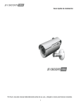
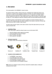
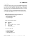
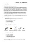
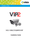
Please read this manual thoroughly before use, and keep it handy for future reference. Quick Installation Guide VK2-1080VRDIR37e Quick Guide V1.0 2 Quick Installation Guide 1. Description This manual applies to the VK2-1080VRDIR37e full HD Vandal resistant varifocal dome with IR illumination. • Installation Steps Follow these steps to install the VK2-1080VRDIR37e on your local network (LAN): 1. 2. 3. 4. • Check the package contents against the list below. Connect the VK2-1080VRDIR35V16e Set an IP address. Set the password. Package Component The system comes with the following components: Camera Unit Installation CD Installation Guide Accessory Kit Template sheet Notes: 1. Check your package to make sure that you received the complete system, including all components shown above. 2. Adapter for DC 12V is not supplied. • Contents in the installation CD 1. 2. 3. 4. 5. The The The The The User’s Manual SmartManager User’s Manual VK2-Client User’s Manual SmartManager Installation software VK2-Client Installation software VK2-1080VRDIR37e Quick Guide V1.0 3 Quick Installation Guide • Connection Cable NO 1 2 3 Name Lens Power Cable Ethernet Cable Description Allows wide area to be monitored Cable for Power source (DC 12V) Cable for Ethernet (POE) Camera Dimension See the diagrams below for the exact dimension VK2-1080VRDIR37e Quick Guide V1.0 4 Quick Installation Guide 2. Installation 2.1 Connection • Camera Installation Carefully remove the contents from the box, and verity that nothing was damaged in shipment. 1) Mark the screw hole positions on the ceiling or wall surface using the Template Sheet. 2) Disassemble the camera by removing the dome cover. 3) Mount the camera assembly using the Anchors (x2) and Screws (x2) to the surface of the ceiling or wall 4) Reassemble the dome cover on the camera assembly. Turn Camera Cover clockwise to complete installation • • Connecting to the RJ-45 Connect a standard RJ-45 cable to the network port of the network camera. Generally a cross-over cable is used for directly connection to PC, while a direct cable is used for connection to a hub or switch. Micro SD memory slot Insert the SD memory card. Connecting the Power Connect the DC 12V power adaptor to the camera. (This connection is not used if using PoE power) VK2-1080VRDIR37e Quick Guide V1.0 5 Quick Installation Guide 2.2 Network Connection and IP assignment The Camera supports the operation through the network. When a camera is first connected to the network it has no assigned IP address. So, it is necessary to allocate an IP address to the device with the “Smart Manager” utility found on the supplied CD. The factory default IP is “192.168.30.220”. 1. 2. Connect the Camera / device to the network and power up. Start SmartManager utility (Start>All programs>SmartManager>SmartManager), the main window will be displayed, after a short while any network devices connected to the network will be displayed in the list. 3. Select the camera on the list and click right button of the mouse. You can see the pop-up menu below. 4. Select Assign IP. will see the "Assign IP Address" window. Enter the required IP address. Note: For more information, refer to the Smart Manger User’s Manual. VK2-1080VRDIR37e Quick Guide V1.0 6 Quick Installation Guide 3. Operation The Camera can be used with Windows operating system and browsers. The recommended browsers are Internet Explorer, Safari, Firefox, Opera and Google Chrome with Windows. 3.1 Access from a browser 1. 2. 3. Start a browser. (Internet Explorer) will be used in this example. Enter the IP address or host name of the Camera in the Location/Address field of your browser. You can see a starting page. Click Live View or Setup to enter web page. 4. The network camera’s Live View page appears in your browser. 3.2. Access from the internet Access from the internet once connected, the Camera is accessible on your local network (LAN). To access the Camera from the Internet you must configure your broadband router to allow incoming data traffic to the network camera. To do this, enable the NAT-traversal feature, which will attempt to automatically configure the router to allow access to the network camera. This is enabled from Setup > System > Network > NAT. For more information, please see “3.5.5 System>Network>NAT” of User’s Manual. VK2-1080VRDIR37e Quick Guide V1.0 7 Quick Installation Guide 3.3 Setting the admin password over a secure connection To gain access to the product, the password for the default administrator user must be set. This is done in the “Admin Password” dialog, which is displayed when the Camera is accessed for the setup at the first time. Enter your admin name and password, set by the administrator. Note: The default administrator username and password is “admin”. If the password is lost, the Camera must be reset to the factory default settings. See “3.6 Resetting to the Factory Default Settings”. 3.4 Live View Page The live view page comes in several screen modes:1920x1080, 1280x1024, 1280x720, 704x480(576),640x480,352x240(288) and 320x240. Users are allowed to select the most suitable one out of those modes. Please, adjust the mode in accordance with your PC specifications and monitoring purposes. 1) General controls Live View Page Search & Playback Page Setup Page Help Page The video drop-down list allows you to select a customized or pre-programmed video stream on the live view page. Stream profiles are configured under Setup > Basic Configuration > Video & Image. For more information, please see “3.5.1 Basic Configuration > Video & Image” of User’s Manual. The resolution drop-down list allows you to select the most suitable one out of video resolutions to be displayed on live view page. The protocol drop-down list allows you to select which combination of protocols and methods to use depending on your viewing requirements, and on the properties of your network. VK2-1080VRDIR37e Quick Guide V1.0 8 Quick Installation Guide 2) Control toolbar The live viewer toolbar is available in the web browser page only. It displays the following buttons: The Stop button stops the video stream being played. Pressing the key again toggles the start and stop. The Start button connects to the Camera or start playing a video stream. The Pause button pause the video stream being played. The Snapshot button takes a snapshot of the current image. The location where the image is saved can be specified. The digital zoom activates a zoom-in or zoom-out function for video image on the live screen. The Full Screen button causes the video image to fill the entire screen area. No other windows will be visible. Press the 'Esc' button on the computer keyboard to cancel full screen view. The Manual Trigger button activates a pop-up window to manually start or stop the event. 3) Video Streams The Camera provides several images and video stream formats. Your requirements and the properties of your network will determine the type you use. The Live View page in the Camera provides access to H.264, MPEG-4 and Motion JPEG video streams, and to the list of available video streams. Other applications and clients can also access these video streams/images directly, without going via the Live View page. 3.5 Camera Setup This section describes how to configure the network camera, and is intended for product Administrators, who have unrestricted access to all the Setup tools; and Operators, who have access to the settings for Basic, Live View, Video & Image, Event, and System Configuration. You can configure the Camera by clicking Setup in the top right-hand corner of the Live View page. Click on this page to access the online help that explains the setup tools When accessing the Camera for the first time, the “Admin Password” dialog appears. Enter your admin name and password, set by the administrator. Note: If the password is lost, the Camera must be reset to the factory default settings. See “3.6 Resetting to the Factory Default Settings”. VK2-1080VRDIR37e Quick Guide V1.0 9 Quick Installation Guide 3.6 Resetting to the factory default settings To reset the Camera to the original factory settings, go to the Setup>System> Maintenance web page (described in User’s Manual, “3.5.5 System > Maintenance”) or use the Reset button on the network camera, as described below Reset Button • Using the Reset Button Follow the instructions below to reset the Camera to the factory default settings using the Reset button. 1. Switch off the Camera by disconnecting the power adapter. 2. Press and hold the Reset button with a straightened paperclip while reconnecting the power. 3. Keep the Reset button pressed for at least 2 or more seconds. 4. Release the Reset button. 5. The Camera resets to factory defaults and restarts after completing the factory reset. Caution: When performing a Factory Reset, you will lose any settings you have saved. (Default IP 192.168.30.220) 3.7 More Information For more information, please see the Camera User’s Manual, which is available on the CD included in this package. VK2-1080VRDIR37e Quick Guide V1.0 10 Quick Installation Guide VK2-1080VRDIR37e Quick Guide V1.0 11 Quick Installation Guide Printed in Korea VK2-1080VRDIR37e Quick Guide V1.0 12