1
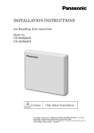
INSTALLATION INSTRUCTIONS
Air Handling Unit control kit
Model No.
CZ-280PAH1
Caution
Only Indoor Installation
Carefully reading this ”INSTALLATION INSTRUCTIONS”, correctly
and safely conducting installation or electrical work.
Especially, before conducting installation or electrical work, be sure to
read ” Safety Precautions”(page3).
Contents
1.
Safety Precautions
3
2.
System Lineup
4
3.
Supplied Parts
4
4.
Outside View
4
5.
Control Box Configuration
5
6.
System Overview
5
7.
Limitation of AHU
6
7.1. Temperature range
6
7.2. Inside volume of heat exchanger
6
7.3. Air volume of AHU
6
7.4. Front area of heat exchanger
6
7.5. Restriction of the number of passes of the heat exchanger hairpin
6
8.
Installation
7
8.1. AHU kit Installation
7
8.2. Piping Installation
8
8.3. Thermistor Installation
9
8.4. Capacity disregard of circuit board in outdoor unit
10
8.5. Remote Controller Installation(Option parts)
11
9.
Electrical Wiring
13
9.1. General Precautions on Wiring
13
9.2. Recommended Wire Length and Wire Diameter for Power Supply System
13
9.3. Wiring System Diagrams
14
9.4. How to connect wiring to the terminal
16
9.5. Connecting Distant Signal Line
17
10.
Test Run
18
Warranty policy
We are held responsible for the quality and performance of the AHU kit we supply, but not held
responsible for the performances, operations and machine controls of your complete AHU system which
incorporates our AHU kit.
We are not held responsible for the components used in the refrigerant cycle of your AHU system either.
Such components are, but not limited to,
Compressors, High-pressure switches, Check valves, Strainers, Expansion valves,
Solenoid valves, 4-way valves, Capillary tubes, Accumulator tanks, Heat exchanger tubes.
We are not held responsible for any damages and defects caused in the process of installing our AHU
kit, by the system design and/or during assembly of your AHU system.
We do not publish the certificate to show conformity to the EMC and the product safety requirements
applicable to your complete AHU system.
2
1. Safety Precautions
z Before conducting installation or electrical work, be sure to carefully read these” Safety Precautions”.
Follow instructions exactly in all installation or electrical work.
z The following symbols used in this manual, alert you to potentially dangerous conditions to users,
service personnel or the appliance:
Warning
This warning mark indicates that
“A possibility of serious injury or
death exists”.
Caution
This cautionary mark indicates
that “A possibility of injury or
damage to property exists”.
Warning
z Be sure to arrange installation at the dealer where the system was purchased or use a
professional installer. Leaks, electric shock or fire may result if an inexperienced person performs
any installation or wiring procedures incorrectly.
z Installation should be performed exactly according to the “Installation Instructions”. Electric
shock or fire may result if an inexperienced person performs any installation or wiring procedures
incorrectly.
z Only a qualified electrician should attempt to install this system, in accordance with the
provisions of “Installation Instructions”.
Be sure to use a dedicated electrical circuit. Insufficient electrical circuit capacity or inadequate
workmanship may cause electric shock or fire.
z Always use a dedicated branch circuit for electrical wiring. Do not use with any other electric
devices. Use with other electric devices may result in circuit breaker breaks.
z Use the specified cables (type and wiring diameter) for the electrical connections, and securely
connect the cables. Run and fasten the cables securely so that external forces or pressure placed
on the cables will not be transmitted to the connection terminals. Overheating or fire may result
if connections or attachments are not secure.]
z Install so that even if cooling gas leaks into the room, it will not exceed the limit density of
0.3kg/m3, in accordance with the standard for facility air conditioning equipment (S0010). If it
does exceed the limit density, install an opening in a neighboring room, or install ventilation
equipment triggered by gas leak detection sensors. Suffocation can result if cooling gas leaks and
exceeds the limit density in a small room.
z Install in a location that is fully strong enough to support the weight of the equipment. If it is not
strong enough, the equipment may fall, resulting in injury.
z Perform installation that is secure enough to withstand earthquakes, and typhoons and other
strong winds. Incorrect installation can result in falling equipment and other accidents.
z Ventilate the work area if cooling gas leaks during installation. Poisonous gas can result if cooling
gas comes into contact with fire.
z After installation of cooling pipes, perform a nitrogen gas sealing test to check that there are no
leaks. Poisonous gas can result if cooling gas leaks into the room and comes into contact with a
fan heater, stove, range, or other source of fire.
Caution
z When handling cooling gas, be careful not to touch the cooling gas directly. Frostbite injuries can
occur.
z Do not install the system in locations where flammable gas can be generated, enters, build up, or
leak. Do not install in locations where volatile inflammable materials are handled. Flammable
gas or inflammable materials may ignite, cause fires.
z Be sure to ground equipment properly. Do not attach ground wires to gas pipes, water pipes,
lightning arresters, or telephone ground lines. Failure to ground completely can cause electric
shock.
z Always install an earth leakage breaker. Failure to install an earth leakage breaker can cause
shock and fires.
3
2. System Lineup
Capacity
10kW
12.5kW
14kW
20kW
25kW
Outdoor combination
U-100PE1E8
U-100PE1E5
U-125PE1E8
U-125PE1E5
U-140PE1E8
U-140PE1E5
-
U-200PE1E8
-
U-250PE1E8
Connectable AHU-kit combination
CZ-280PAH1
CZ-280PAH1
CZ-280PAH1
CZ-280PAH1
CZ-280PAH1
CZ-280PAH1
-
CZ-280PAH1
-
CZ-280PAH1
*Single connection type only.
*Mix connection with standard indoor units is not allowed.
*Applicable system is only above.
3. Supplied Parts
Part name
Self DrillingScrew
(4x13)
Form
Quantity
Notes
7
For fixing the product.
(Kit and its bracket)
Screw(4x8)
2
For attaching
(option parts)
Bracket
1
For supporting the product.
At the time of shipment, be glued to
the back of the product.
Installation
Instructions
User’s manual
remote controller.
1
AHU System
Check list
1
For selection of AHU and
operating test run.
Insulation
2
For thermistor insulation
Clamper
5
For fixing thermistor ,and
making wire down to Blower
signal line.
Thermistor
3
Attached to the body of AHU kit.
Notes
1
Paste notes on an outdoor unit.
4. Outside View
Weight of the control box:6.3kg
4
5. Control Box Configuration
① PCB(main)
② Transformer
③ Magnetic relay
④ Terminal(power supply, control line)
⑤ Terminal(Blower signal line)
⑥ Space Optional controller installation
(for Mini Seri-Para I/O unit <CZ-CAPBC2>)
6. System Overview
Single connection
Strainer(Liquid pipe &
Gas pipe)Minφ25.4、
#100(Field supplied)
A:AHU kit controller box (with control PCB)
B:AHU equipment (Field supplied)
C:Remote controller (option parts)
D:Outdoor unit
E:Gas piping (Field supplied)
F:Liquid piping (Field supplied)
G:Thermistor for Liquid pipe(E1)
H:Thermistor for Heat exchanger pipe middle(E2)
I:Thermistor for Suction air(TA)
J:Inter unit wiring
K:Magnetic relay for operating the blower(Field supplied)
5
7.
Limitations of AHU
7.1. Temperature Range
The limitation of temperature range is below.
Outdoor temperature
Inter air temperature
(to the heat exchanger)
Cooling
-10℃(DB)
43℃(DB)
18℃(DB)
32℃(DB)/23℃(WB)
Minimum
Maximum
Minimum
Maximum
Heating
-20℃(WB)
15℃(WB)
16℃(DB)
30℃(DB)
7.2. Inside Volume of Heat Exchanger
Capacity(Cooling)
Heat exchanger
Maximum
volume
Minimum
kW
dm3
dm3
10
2.1
1.7
12.5
2.1
1.7
14
2.1
1.7
20
4.3
2.3
25
4.3
2.7
7.3. Air Volume of AHU
Capacity(Cooling)
Maximum
Air volume
Minimum
kW
m3/h
m3/h
10
1980
840
12.5
2100
1140
kW
㎡
㎡
10
0.51
0.43
12.5
0.51
0.43
14
2160
1140
20
3960
1680
25
4440
2280
7.4. Front Area of Heat Exchanger
Capacity(Cooling)
Maximum
The frontal area
Minimum
14
0.51
0.43
20
1.0
0.54
25
1.0
0.66
7.5. Restriction of the Number of Passes of the Heat Exchanger Hairpin
Minimum number of passes
=The number of steps×Distance between tube sheets×The number of rows×1.5×10⁻⁴
<For example>
The number of steps: 12
Distance between tube sheets : 1000[mm]
The number of rows : 3
∴Minimum number of passes = 12×1000×3×1.5×10-4 =
5.4 <
6 passes
Caution
Outdoor unit has a switch for high-pressure. Air-conditioning unit stops the operation
for protection when high-pressure gets higher.
Pressure switch sometimes operates in Heating mode when the position of setting
Heat exchanger pipe Thermistor (E2) is not proper or how to set it is not proper.
6
8. Installation
8.1. AHU kit Installation
Mount AHU kit according to the following instructions.
* Attach AHU kit to Air Handling Unit body directly to avoid exposing wires of thermistors to
outside.
1. Install the bracket to the wall with
the screws.(Three screws)
2. Make two holes. (for wirings)
The position of wires holes of AHU kit
120mm
6mm
25mm
7mm
113mm
70mm
3. Hang the kit on the bracket.
4. Remove the two screws on the right
side of the unit.
(Support the unit with your free hand
while removing the screws.)
300mm
Obstacle
5. Open the front panel and fix the unit to the
wall with the screws.(4 screws)
7
8.2. Piping Installation
8.2.1. Dimension of connecting pipe to heat exchanger of AHU
Capacity
10-14kW
Model name
CZ-280PAH1
Liquid pipe
Φ9.52mm
Gas pipe
Φ15.88mm
20kW
CZ-280PAH1
Φ9.52mm
Φ25.4mm
25kW
CZ-280PAH1
Φ12.7mm
Φ25.4mm
8.2.2. System piping length(Charging with refrigerant)
At the time of shipment from the factory, Outdoor unit is charged with enough refrigerant for an
equivalent pipe length of 30m.
If the equivalent pipe length used will be 30m or less, no additional charging will be necessary.
If the equivalent pipe length will be between 30 and 50 / 70m, charge with additional refrigerant
according to the equivalent length given in the table below.
Capacity
10-14kW
Additional charging amount
50g/m
Equivalent length
50m
Minimum length
5m
20kW
40g/m
70m
5m
25kW
80g/m
70m
5m
8.2.3. Installation of Strainer(Field supplied)
Attach the Strainer to the side of the outdoor unit for GAS & LIQUID piping.
(Refer to 6 System Overview of page 5)
8
8.3. Thermistor Installation
Identify the thermistors by the tag which is wound to each thermistor.
* Don’t put wires out of equipment.
* Don’t cut wires and don’t detach connecter of wires.
8.3.1. Caution for Thermistor Installation
Attach the head of thermistor exactly
onto the pipe because the head is most
sensitive point of the thermistor.
Put the thermistor wire down to avoid
water to the thermistor.
Maximize the contact
Most sensitive point
of the thermistor
Insert thermistor wire down into AHU
body. The wire down is close to AHU kit.
Inside of AHU
AHU kit
Wire Down
Drooping
Wire
8.3.2. Thermistor Installation for Liquid Pipe
Put “E1” thermistor to liquid pipe of AHU heat exchanger according to the step below.
1. Attach the liquid thermistor to the liquid
pipe located in the lowest position after
distributer in heat exchanger.
2. Cover the thermistor and pipe with
aluminum tape.
3. Cover the aluminum tape with thermal
insulation.
4. Thermal insulation and wiring are fixed
by two bands. Then, it must not make
tension to the wire.
Put the thermistor
wire down
9
8.3.3.
Installation of “E2”Thermistor for Heat exchanger Pipe middle
1. Attach the heat exchanger pipe middle
thermistor in the middle of each pass-line
(pipe) in the heat exchanger.
3. The thermistor is fixed in bands. Then,
it must not make tension to the wire.
2. Cover the thermistor and pipe with
aluminum tape(Field supply).
4. Cover the aluminum tape with thermal insulation.
And also cover Sensor(Copper portion) with
thermal insulation completely.
8.3.4. Thermistor Installation for Air (Suction )
Attach Suction Thermistor (TA) to the position where air suction temperature can be measurable.
8.4. Capacity Disregard of Circuit Board in Outdoor Unit
Cut the wire for jumping to “JP001(Capacity disregard)” on circuit board in outdoor unit. Remote
Controller displays “E15, E16(Error message)” when not cutting it.
Take off cut jumper leads.
10
8.4.1.
Attachment of NOTES Label.(Supplied parts)
Please be sure to place the attached NOTES label on the following designated area in Outdoor Unit
when cutting jumper wire on circuit board in Outdoor Unit.
Model name
U-100PE1E8
U-125PE1E8
U-140PE1E8
U-100PE1E5
U-125PE1E5
U-140PE1E5
U-200PE1E8
U-250PE1E8
NOTES
NOTES
8.5. Remote Controller Installation (Option parts)
When you install a remote controller (Option parts), follow the steps below.
① Remove the front panel
1. Remove the two screws on the right
side of the unit.
3. Remove the screw and washer fixing
film on the front panel.
2. Open the front panel.
4. Remove hinges and lift up the front
panel.
11
② Make holes on the front panel
Make holes (x3) correctly at the following position. (2 screw holes, a wire hole)
Caution
2×Φ3.1mm
Hole for screws of remote
controllerLess
installation
than 180mm
Φ10mm
Hole for remote
control
lerfor
wiring
Hole
remote
controller wiring
If the hole position is wrong or
different, the electrical
equipment parts in the box and
the wires may be damaged and
cause the trouble.
Φ10mm Hole
2×Φ3.1mm Hole
Front view
Top view
③ Remote controller installation
1. Push the driver into the groove of the lower body of the remote control, and then remove the
lower case.
2. Fixed the case of the remote control with screws onto the front panel.
3. Connect the remote control wiring to the main PCB of AHU kit.
4. Fit the body of the remote control to the lower case, and then install it.
Hole for remote
controller wiring
Caution
Use the two screws(4x8)
that come with this AHU
kit instead of the four
screws that come with the
remote controller.
Lower case of the
remote controller
Screw(4x8)×2
(Supplied
Parts)
Hole for remote
controller installation
Body of the
remote controller
④ Attach the front panel
1. Replace front panel.
2. Fix the film to the front panel with the screw and washer.
3. Close the front panel.
4. Replace the two screws on the right side of the unit.
12
9. Electrical Wiring
9.1. General Precautions on Wiring
(1) Before wiring, confirm the rated voltage of the unit as shown on its nameplate, then carry out
the wiring closely following the wiring diagram.
(2) This equipment is not provided with a power supply cord. Circuit breaker must be incorporated
in the fixed wiring in accordance with national wiring regulations. The circuit breaker must be
approved, suitable for the voltage and current ratings of equipment and have a contact
separation in all poles.
(3) To prevent possible hazards from insulation failure, the unit must be grounded.
(4) Each wiring connection must be done in accordance with the wiring system diagram. Wrong
wiring may cause the unit to misoperate or become damaged.
(5) Do not allow wiring to touch the refrigerant tubing, compressor, or any moving parts of the fan.
(6) Unauthorized changes in the internal wiring can be very dangerous. The manufacturer will
accept no responsibility for any damage or misoperation that occurs as a result of such
unauthorized changes.
(7) Regulations on wire diameters differ from locality to locality. For field wiring rules, please refer
to your LOCAL ELECTRICAL CODES before beginning.
You must ensure that installation complies with all relevant rules and regulations.
(8) To prevent malfunction of the air conditioner caused by electrical noise, care must be taken
when wiring as follows:
● The remote control wiring and the inter-unit control wiring should be wired apart from the
inter-unit power wiring.
● Use shielded wires for inter-unit control wiring (between units) and ground the shield on both
sides.
(9) If the power supply cord of this appliance is damaged, it must be replaced by a repair shop
designated by the manufacture, because special-purpose tools are required.
9.2. Recommended Wire Length and Wire Diameter for Power Supply System
Type
AHU kit controller
(B) Power supply
2.5mm2
Max. 150m
Time delay fuse or
circuit capacity
10-16 A
Control wiring
(C) Inter-unit
(between outdoor and indoor units)
control wiring
0.75mm2
(AWG#18)
Use shielded wiring*
Max. 1,000m
(D) Remote control
wiring
0.75 mm2
(AWG#18)
Max. 500m
*For ”(A) Power supply of outdoor unit”, refer to “INSTALLATION INSTRUCTIONS” of outdoor
unit.
13
9.3. Wiring System Diagrams
Fig.9-1
(1) Refer to Section 9.2. “Recommended Wire
Length and Wire Diameter for Power Supply
System” for the explanation of “A”, “B”, “C”
and “D” in the above diagram. (Fig.9-1)
(2) The basic connection diagram of the indoor
unit shows the terminal boards, so the
terminal boards in your equipment may differ
from the diagram.(Fig.9-2)
(3) Refrigerant Circuit (R.C.) address should be
set before turning the power on.
(4) Regarding R.C. address setting, refer to the
installation instructions supplied with the
remote controller unit(optional). Auto address
setting can be executed by remote controller
automatically. Refer to the installation
instructions supplied with the remote
controller unit(optional).
14
Fig.9-2
(1) When linking the outdoor units in a network, disconnect the terminal extended from the short plug
from all outdoor units except any one of the outdoor units.
(When shipping: in shorted condition.)
For a system without link(no wiring connection between outdoor units), do not remove the short
plug.
(2) Do not install the inter-unit control wiring in a way that forms a loop.(Fig.9-3)
Fig.9-3
(3) Do not install inter-unit control wiring such as star branch wiring. Star branch wiring causes
mis-address setting.(Fig.9-4)
Fig.9-4
(4) If branching the inter-unit control wiring, the number of branch points should be 16 or
fewer.(Branches that are less than 1m are not included in the total branch number.)(Fig.9-5)
Fig.9-5
(5) Use shielded wires for inter-unit control wiring(c)
which shielded woven mesh grounded on both
sides, otherwise misoperation from noise may
occur.(Fig.9-6)
Connect wiring as shown in Section” 9.3.Wiring
System Diagrams”.
Fig.9-6
(6) Use the standard power supply cables for Europe
(such as H05RN-F or H07RN-F which conform to
CENELEC(HAR) rating specifications) or use the
cables based on IEC standard.(245 IEC57, 245
IEC66)
15
Loose wiring may cause the terminal to
overheat or result in unit malfunction. A
fire hazard may also occur. Therefore,
ensure that all wiring is tightly connected.
When connecting each power wire to the
terminal, follow the instructions on “How
to connect wiring to the terminal” and
fasten the wire securely with the terminal
screw.
9.4. How to Connect Wiring to the Terminal
■ For stranded wiring
(1) Cut the wire end with cutting pliers, then strip the insulation to expose the stranded wiring by about
10mm and tightly twist the wire ends. (Fig.9-7)
(2) Using a Phillips head screwdriver, remove the terminal screw(s) on the terminal plate.
(3) Using a ring connector fastener or pliers, securely clamp each stripped wire end with a ring pressure
terminal.
(4) Place the ring pressure terminal, and replace and tighten the removed terminal screw using a
screwdriver.(Fig.9-8)
Fig.9-7
Fig.9-8
■ Examples of shield wires
(1) Remove cable sheath not to scratch braided shield.
(Fig.9-9)
(2) Unbraid the braided shield carefully and twist the
unbraided shield wires tightly together. Insulate the
shield wires by covering them with an insulation tube
or wrapping insulation tape around wire. (Fig.9-10)
(3) Remove insulation of signal wire.(Fig.9-11)
(4) Attach ring pressure terminals to the signal wires and
the shield wires insulated in Step (2).(Fig.9-12)
Use this screw
when connecting
the shield for the
inter-unit control
wiring to ground
Fig.9-10
Fig.9-11
Fig.9-12
Remote Control
Wiring
Power Supply
Fig.9-9
Inter-unit Control
Wiring
16
9.5. Connecting Distant Signal Line(Blower signal and Blower protect)
Blower signal and Blower protect are connected
from this hole and fixed by clamper.
Inside of AHU
Blower signal and
Blower protect
Clamper(Supplied parts)
Drooping wire
Make wire down to Blower signal and
Blower protect by clamper(Supplied parts) so as to
avoid water into AHU kit.
■ Blower signal output
A fan control. It is usually at ON position at the time of operating, but it becomes OFF in defrosting.
■ Blower protect input
If a switch opens, an alarm “P01” appears on a remote control display, and stop operation stops.
17
10. Test Run
Operate Test Run according to “10.PRECAUTIONS REGARDING TEST RUN”(10-14kW), “9.TEST
RUN” (20-25kW) which is in INSTALLATION INSTRUCTIONS of Outdoor Unit and “AHU System
Check List” which is an accessory of this product.
If alarm messages are indicated on the outdoor unit PCB (blink of LED) or the wired remote controller,
refer to“Check self-diagnosis label attached on the reverse side of the panel for checking the
Unit.”(10-14kW) “9-7. Table of Self-Diagnostic Fanctions and Corrections” (20-25kW) which is in
INSTALLATION INSTRUCTIONS of Outdoor Unit.
18
PA0612-1082
Authorized representative in EU
Panasonic Testing Centre
Panasonic Marketing Europe GmbH
Winsbergring 15, 22525 Hamburg, Germany
85464369641001
Printed in Japan
Service Part No, CV6233211466