1
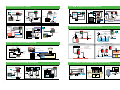
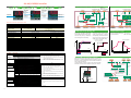
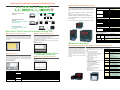
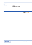
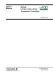
DAQWORX
DAQWORX
DAQWORX is an integrated data acquisition software package that is highly
scalable—it will respond flexibly to constant market changes. Combine DAQWORX
with Yokogawa recorders, data acquisition stations and units, instrumentation, and
measuring instruments to build a user-friendly, PC-based data acquisition system.
With its three classes of software components—Base, Add-on and Gate—DAQWORX
will support changes to your system in response to future market demands. Leaving
your existing data acquisition system unmodified, you can simply incorporate our
recorders, data acquisition units, and high-value-added software to tailor your system
for specific needs.
• Data Acquisition Components
The “Base” software components require neither technical expertise nor
programming, enabling you to easily set up hardware and start operating your data
acquisition system as soon as possible.
• High-Value-Added Components
The “Add-on” software components offer advanced functionssuch as customized
windows, monitoring clients, multi-logging, and data acquisition trigger
conditioning.
• Interface Components
The “Gate” software components enable data acquisition using power measuring
instruments and Modbus devices in combination with data acquisition units. With
these components, you can quickly connect OPC servers and network cameras.
• DataBrowser
Easily and quickly search files and display results in waveform
– Display measured data of different interval and different models on the same
time axis
– Easy data comparison based on the first data or trigger point.
Software Component
Data Acquisition Components
DAQLOGGER: General-purpose medium-speed (1 s max.) data acquisition
supports to major data acquisition equipment models
DAQ32Plus:
High-speed (500 ms max.) data acquisition tool for use with
DARWIN
MXLOGGER:
Ultra high-speed (10 ms max.) data acquisition tool for use with
DAQMASTER
DAQEXPLORER: Automatic data file acquisition tool for use with DAQSTATION
and MobileCorder
High-Value-Added Components
AddObserver:
Graphical human-machine interface (HMI) for creating
monitoring
windows for the operator
AddMulti:
Acquires data through groups of channels on a group-by-group
basis by combining various measurement conditions
AddTrigger:
Performs advanced data logging using a wide variety of trigger
conditions
DAQLOGGER Client:
Networked remote monitoring client software for DAQLOGGER
DAQ32Plus Client:
Networked remote monitoring client software for DAQ32Plus
AddObserver Runtime:
Networked remote monitoring runtime software for AddObserver
Interface Components
GateEye:
An interface for distributing images from network cameras to
DAQObserver
GateOPC:
An interface for data acquisition from OPC servers to
DAQLOGGER
GateWT:
An interface for data acquisition from WT-series power meters
to DAQLOGGER
GateDX-P:
An interface for data acquisition from DX100P/200P to
DAQLOGGER
GateMODBUS: An interface for data acquisition from MODBUS devices to
DAQLOGGER
GateMX100:
An interface for data acquisition from MX100 to DAQLOGGER
or
Add-on software.
GateµR
An Interface for data acquisition from µR10000 to
DAQLOGGER.
GateCONTROL Temperature controller (Green/UT100) and JUXTA(VJ series)
can be easily
connected to DAQLOGGER.
Digital Indicating Controllers
SELECTION GUIDE
Indicating Controllers
Process Controller
Program Controllers
Indicators with Alarms
Manual Setters
<Example for Connection>
●GateModbus is a software interface for connecting devices that support the
Modbus protocol with DAQLOGGER data logging software.
Allows connection of controllers, power monitors, and signal conditioners to
the network (Modbus/TCP) for a small scale instrumentation system that
can be set up quickly.
●Reads the input and holding registers from up to 200 channels of various
measuring instruments.
●Supports the Ethernet (Modbus/TCP protocols)
●AddObserver monitor design software, an add-on for DAQLOGGER, lets
you create the custom monitors that are optimal for your measuring
environment.
DAQSTATION
DAQSTATION
DX100/DX200
CX1000/CX2000
Network
Data Acquisition
Ethernet
Ethernet Arrester AR2
Ethernet
Digital Indicating Controller
Data Server
Digital Indicating Controller
Ethernet
(10Base-T)
R
LR67174C
YOKOGAWA ELECTRIC CORPORATION
Network Solutions Business Div./Phone: (81)-422-52-7179, Fax: (81)-422-52-6793
E-mail: [email protected]
YOKOGAWA CORPORATION OF AMERICA
YOKOGAWA EUROPE B.V.
YOKOGAWA ENGINEERING ASIA PTE. LTD.
20
Phone: (1)-770-253-7000, Fax: (1)-770-251-2088
Phone: (31)-33-4641806, Fax: (31)-33-4641807
Phone: (65)-62419933, Fax: (65)-62412606
Subject to change without notice.
[Ed : 02/b] Copyright ©2003
Printed in Japan, 506(KP)
Distribué par :
FM
APPROVED
Bulletin 05A01A01-01E
RS-14E
System
DISTRIBUTEUR CONSEIL DEPUIS 1985
2 rue René Laennec 51500 Taissy France
Fax: 03 26 85 19 08, Tel : 03 26 82 49 29
Email : [email protected]
Site web : www.hvssystem.com
21
A Complete Range of E xceptional Controllers
Select the One Suitable for Your Needs from YOKOGAWA Digital Indicating Controllers
96 96
(1/4DIN)
UM351
Indicator with Alarms
with Active Color PV Display
UP351
UP550
UP750
Program Controller
with Active Color PV Display
Program Controller
Program Controller
UT351
Indicating Controller
with Ethernet
& Active Color PV Display
UT450
Indicating Controller
UT551
Indicating Controller
with Ethernet
& Active Color PV Display
UT750
US1000
Indicating Controller
Process Controller
(72144mm)
48 96
(1/8DIN)
UM331
UT321
UT420
UT520
LL100,LL1100
LL200,LL1200
Indicator with Alarms
with Active Color PV Display
Indicating Controller
with Active Color PV Display
Indicating Controller
Indicating Controller
Parameters Setting Tool
Custom Computation
Building Tool
UT130
UT150
UP150
Indicating Controller
Indicating Controller
Program Controller
48 48
(1/16DIN)
(Unit:mm)
2
3
For food and pharmaceutical industries
For industrial furnace control
Electric furnace
For food and pharmaceutical industries
Heating/cooling control
Drive the control motor
UT551
Recorder
UT450
Alarms
UP351
Pharmaceuticals
Fan
Wrapping
machine
control
UT450
eggs
Feed
control
Remote SP
Thermocouple
SCR
Wrapping machine
YP series thyristor
Electric furnace
UP750
µR series recorder
Alarm output
O 2 Temp.
Optimum controllers for process control
PV switching
Vacuum sintering
furnace
TC
Furnace
Oven temperature monitor
Vacuum sintering furnace control
UT750
O 2 Signal
PLC
Gas
Thermocouple
Carbon Potential control
Oxygen
sensor
Heater
SCR
Burner
YP series thyristor
UT130
Sealing
temperature Roll
temperature
PLC
UT450
Air
SCR
Water
Spray
Chamber
Feedback
Cooling
water
Food wrapping machine
Heat source
Control
motor
Heating
(4 to 20 mA DC signal)
Heating unit
4 to 20 mA DC
Incubator control
Communication
UP550
Cooling (relay signal)
Retransmission
output
Thermocouple
Temperature control for sterilization
Furnace Temp.
Materials
Feed-forward control
UT750
Custom
computation
Withdrawal
Radiation command
thermometer
Natural gas
Cascade control
Control
US1000
Secondary PV input
Primary PV input
Retransmission output
(4 to 20 mA DC)
Waste water
flow rate
TC
Thermocouple
4 to 20 mA
Thermocouple
SCR
Burner control
pH signal
UM331/UM351
Air
Endo gas
Waste water
Flow meter
µR series recorder
pH sensor
M
Neutralizer
Hot water
Neutralized waste water
For plastics processing and forming
The UT2800 series is optimum for 3- to 4-zone heating/cooling control.
DCS or PLC
Heater
Graphic display
Cooling water
US1000
Cold water
Relay output
(cooling side)
SSR
US1000 executes
backup control
when DCS or PLC fail.
Master
controller
Fuel flow
controller
Air flow
controller
US1000
PV
Heating/cooling
CT
Combustion control
Backup control
Control of extruders
Product
UT2800
Fail signal
For electronics and
semiconductor manufacturing
MV
Voltage pulse output
(heating side)
Fuel
PLC
UT150
Heater burnout alarm
Air
Communication
For electronics and semiconductor manufacturing
For environmental testing and control
External setpoints switching
Alarm output
Dual-loop control
UT750
PLC or switch
µR series recorder
Temperature and Humidity control
Control 1
Control 2
Switch-on signal
Raise
Lower
Control
Heating/cooling
control
Cleaning fluid temperature
UP750
Steam
4 to 20 mA DC
SCR
4 to 20 mA
SCR
Thermocouple
SCR
Temperature control with high accuracy
Raw material
Timer Time Lapse signal
Wet-bulb
temperature
Raw
material
Control of reflow furnaces
UP750
Dry-bulb
temperature
UT450
Control of cleaning equipment
SCR
Heater
UT320
Cooling water
UT150
Coolant
Coolant
4
5
Model UT551 & UT351 with Industrial Ethernet
Universal Input/Output
Enhancing automation and process connectivity!
Easy-to-change input and output types
Universal Input
Selectable among TC, RTD, mV and DC voltage.
Plug & Play Operation
The type of input signal and input range can be changed at the customer side by some key operation or by using LL100 or LL1100
ETHERNET-based architecture allows new processes to be added as easily. –No need for extensive hardware
to connect and run the application, because all information is managed on the server.
Thermocouple Type
: K, J, T, B, S, R, N, E, L, U, W, PL-2, PR20-40, W97Re3-W75Re25
RTD Type
: Pt100, JPt100
Works with any Modbus TCP/IP compliant software. MODBUS function codes 03,06,08 & 16 are available.
DC Voltage Input
: 0.4 to 2V, 1 to 5V, 0 to 2V, 0 to 10V, 0.00 to 1.25V(Note), -10 to 20mV, 0 to 100mV
Reduce labor cost in wiring and setup of communications network.
0.1% Indication Accuracy.
Faster connection speed.
Models UT750, UP750 and US1000 have two universal inputs.
parameter setting tool.
Note: For universal input 2 of UT420,UT450,UT520,UT550,UT750,UP550,UP750 and US1000 only.
Connectable up to two 2-wire transmitters simultaneously.
All GREEN SERIES instruments have a 15V Loop Power Supply (15V LPS) for a transmitter.
Moreover, 24V LPS is also available simultaneously for some instruments as optional function. Model US1000 has two 24V LPS functions.
Applicable models for 24V LPS: UT321/351, UT450, UT550, UM331/351, US1000
Real-time monitoring
Remote maintenance
TC
mV
V
Area-3
Position prop. control for
Control motor
4 to 20mA current
Room
temperature
UT551
Voltage pulse
RTD
Motor drive
On/Off outputs
Relay contact
Position
feedback
slide wire
2-wire
transmitter
Direct Connection to Ethernet
RJ45 connector-100Base-TX/
10Base-T
Model : EJA
Control motor
Motor operated valve
Universal Inputs
Hot air
Universal Control Outputs
Universal Output
Area-2
Area-1
Selectable among Relay, Voltage Pulse and Current outputs.
Relay output: ON/OFF control, Time-proportional PID control
Voltage Pulse output: Time-proportional PID control
Current output: Continuous PID control
Heating/Cooling Control has two sets of universal outputs.
Controllers with Active Color PV Display
Any combinations with Relay, Pulse and Current outputs are available. There are some limitations to UT320/350 controllers.
Drive the Motorized Control Valve by using Position-Proportional PID.
See the status of your process conditions
Alarm Status
Active color display changes from Green (normal ) to Red (alarm)
INSTANTLY!
Normal
Alarm
Deviation Status
Color changes based on a PV deviation from SP
User-defined Color
Choose between Green or Red display for constant readings
The color of display automaticcally switches
from GREEN to RED or RED to GREN.
The position-proportional PID control function has two sets of relay outputs for direct / reverse rotation of motorized control valve.
The side wire input to feed back the valve position is also available.
Simple Operation
Fewer key strokes during normal operation
Simple Key Operation
Setpoint (SP) can easily be changed: press the
or
key to display the required setpoint and then press the
key to resister it.(See the figure on the right.)
SET/ENT
For a programmable controller, display the pattern signal
key to start the operation. Press the
and press the
key to stop the operation.
RUN
RESET
Security Functions with Password
UT551
Controller
UT351
Controller
UT321
Controller
UP351
Program Controller
UM351
Indicator
UM331
Indicator
Press the
or
key
to display the required
setpoint (SP).
A password can be set to prevent accidental or deliberate
change to the setup parameter settings of the controller.
SET/ENT
Press the
key to register the setpoint (SP).
Applicable models:All the models of GREEN Series (except for UT130,UT150,UT152
and UT155)
6
7
Powerful Control Functions
Various functions for freely creating input/output-related computations
Communication Functions
14 types of build-in Controller Functions
PV auto-selector
PV switching
Cascade control
SELECT
PID
PID
PID
Dual-loop control
PID
PID
PID
Temperature & humidity control
Relative
Humidity
Calculation
Loop control for backup
PID
PID
PID
Single-loop control
Cascade primary-loop control
Cascade secondary-loop control
Cascade control
Loop control for backup
Loop control with PV switching
Loop control with PV auto-selector
Loop control with PV-hold function
Dual-loop control
Temperature & humidity control
Cascade control with two universal inputs
Loop control with PV switching and two universal inputs
Loop control with PV auto-selector and two universal inputs
Custom computation control
MODBUS Communication
PLC
Personal computer, or PLC
A protocol used for communicating
with a general-purpose personal computer
RS232C/RS485 converter
and PLC.
Protocol: MODBUS RTU
Max. 1200 m; up to 31 slave controllers can be connected
MODBUS ASCII
Baud Rate: 600bps to 38.4kbps
(up to 9,600bps in case of MODBUS.)
GREEN SERIES controllers
CX communication
SUPER Function suppresses overshooting
A CX1000/2000 lets you control external UT controllers with same ease as
CX’s embedded controls.
Connectable models :UT320, UT321, UT350, UT351, UT420, UT450, UT520,
UT550, UT750
The field-proven SUPER function utilizes built-in operator experience and fuzzy theory to deliver fine control and suppress overshooting.
RS485, MODBUS
SUPER: off
Temperature
Temperature
Temperature
SUPER: on
SUPER: on
Time
SUPER: on
CX1000 or CX2000
Time
Time
Startup
Max. external loops:
4(CX1000), 16(CX2000)
(Two-loop controllers count as two loops each.)
Program operation
Disturbance
PLC
Personal Computer Link
Communication
SUPER 2 Function suppresses hunting
A protocol used for communicating with a gen-
The new SUPER 2 function utilizes built-in operator experience and modern control theory to deliver fine control and suppress hunting.
module and serial communication module of
Personal computer, or PLC
RS232C/RS485 converter
eral-purpose personal computer, or UT link
Max. 1200 m; up to 31 slave controllers can be connected
PLC (FA-M3 range-free controller).
Effect 1: For operation of empty furnace with the set PID
When SUPER 2 function is not used
PV
When SUPER 2 function is used
PV
SP PV
FA-M3 and a recorder can be connected in the same line.
GREEN SERIES controllers
SUPER 2 function suppresses hunting.
Operation with load causes
PV hunting.
Time
Time
Effect 2: For changing SP
When SUPER 2 function is not used
Control using SP
with the set PID.
Control using SP
with the set PID.
Changing SP causes hunting.
Time
Coordinated Operation
A protocol used for communicating with a PLC.
In coordinated operation, a UP program controller or
Communication with a computer link unit of the
UT digital indicating controller is used as a master con-
MELSEC-A series (made by Mitsubishi Electric Corpo-
troller and multiple UT digital indicating controllers as
ration) is possible.
slave controllers. The slave controllers are operated in
() FA-M3 is the PLC made by Yokogawa.
accordance with the actions of the master controller.
FA-M3()
PV
PV
8
When SUPER 2 function is used
Ladder Communication
Max. 1200 m; up to 31 slave controllers can be connected
UP program controller or UT digital indicating controller
Max. 1200 m; up to 31 slave controllers can be connected
SUPER 2 function suppresses
hunting even if SP is changed.
Time
GREEN SERIES controllers
GREEN SERIES controllers
9
4848(1/16DIN)Controllers
UT150 Function Block Diagram
UP150 Function Block Diagram
Functional block diagram for Heating & Cooling type UT150 controller.
Lit when SP2 is
being used for
operation.
Lit when the segment no.
or remaining segment
time is displayed on
SP display.
Lit when alarm
occurs.
Lit when SP is
being displayed.
Contact Inputs (/EX)
DI1
DI2
PV Input
SP1
SP2
Lit while the operation
mode is “RUN”.
STOP
UT150
For Heater
Disconnection
Alarm
3 digits
4 digits / 4 digits
1 universal input (TCs, RTDs, mV, V)
1 loop, AUTO mode only
1 loop, RUN/RESET, HOLD/Cancel HOLD
1
2
Number of Program patterns/segments
Control Algorithm
NA
1 program pattern/16 segments
NA
ON/OFF, Time-proportional PID,
ON/OFF, Time-proportional PID,
ON/OFF, Time-proportional PID,
Heating & Cooling
Continuous PID, Heating & Cooling
Continuous PID
SUPER, Auto tuning
SUPER, Dynamic AT
Control Outputs
SUPER
Not available (NA)
Timer function
NA
Digital Outputs
2 (sp1/sp2, RUN/STOP, Timer function)
2 (RUN/RESET, HOLD/Cancel HOLD)
0 second to 1,599 hour
2 (PV event and Time event)
2 (Alarm or Timer outputs)
RS485 Communication Protocols
Two-wire, MODBUS, PC-link, Ladder
Approvals
Size=48*48*100mm, Power supply = 24VAC/DC or 90 to 264V AC, Power consumption=8VA
Ambient T, Limits RH
0 to 50
Output signal
for cooling
Suffix Code
-
-R
-V
N
R
V
/AL
/HBA
Options
Model
UT150
Output signal
(for heating) Note 1
Output signal
for cooling
/RS
/V24
Suffix Code
-
-R
-V
-A
N
R
V
A
/AL
/HBA
Options
/EX
Model
UP150
Output signal
Fixed code
Options
/RET
/RS
/V24
Suffix Code
-
-R
-V
-A
N
/EX
/RET
/RS
/V24
EV2
EV1
Description
Temperature controller
Relay contact output (for time-proportional PID or on/off control)
Voltage pulse output (for time-proportional PID)
No cooling output (Standard type)
Relay contact output (for time-proportional PID)
Voltage pulse output (for time-proportional PID)
Alarm outputs (2 points) Note 1
Heater burnout alarm and 2 other alarm outputs
(includes the functions of /AL) Notes 1, 2, 3
Communication function Note 2
Power Supply 24VDC/24VAC
Temperature Program
Number of program pattern:
One
Accuracy of program time span: +/-2% of span
Program operations:
Wait, Hold, Advance
Up to 16 segments
Time
, 20 to 90%
Time
Time Event Output
Conventional PID control
UT100 control with SUPER
Model and Suffix Codes
Model
UT130
Output signal
(for heating) Note 1
Output
Relay contact,
Voltage Puse or 4 - 20mA
Dynamic AT is started
when SP is changed.
General = UL, CE, CSA Front Protection= IP65
Other specifications
PV Output
4 to 20mA
PV Retransmission
Output (/RET)
Temperature
NA
Temperature
Two timers (0 to 99min.59sec)
NA
Digital Inputs
AL2
The Dynamic Auto Tune function of the
UT130 and UT150 series assures
stabel control. Whenever you change
the setpoint(SP), the function automatically turns the PID parameters and
updates them to the suitable setting.
1 point (4 to 20mA)
NA
Program time span
SUPER control function suppresses
overshooting. The field-proven SUPER
function utilizes build-in operator experience and Fuzzy theory to deliver fine
cotrol and suppress overshooting.
Select from Relay, Voltage Pulse or 4 to 20mA
Select from Relay or Voltage Pulse
PV Retransmission Output
AL1
Relay contact, Voltage Puse or 4 - 20mA
for each output
SUPER Function & Dynamic AT
500ms
Number of Setpoint (SP)
PV & Time
Events
0.3%1digit for mV/V input
Control scan period
Control loops and mode
Cooling Output
Heating Output
4 to 20mA
PV Retransmission
Output (/RET)
1˚C 1digit for RTD
1˚C 1digit for RTD
SUPER & AT
(/AL or /HBA)
PV Output
2˚C 1digit for TC
2˚C 1digit for TC
PID Control
Alarm & Timer
Outputs
RUN
UP150
1 universal input (TCs, RTDs)
Hold/
Re-start
switching
Timer ON
signal
SUPER &
Dynamic AT
UT130/150 and UP150 Specification Table
UT130
DI2
Program Setpoint
Bias & Filtering
STOP/RUN
switching
Rate-of-change
Limiter
Pre-set Output
Indication accuracy
DI1
Run/
Reset
switching
SP selection
Lit while the operation
mode is “HOLD”.
PID Control
PV Input
Contact Inputs (/EX)
PV Input
Functions Selector
Bias & Filtering
EV1: Lit when event 1
is activated.
EV2: Lit when event 2
is activated.
Lit while control
output is
being output.
PV/SP Data display
Heater Current
Detection Input (/HBA)
CT
Notes
Note 1: "/AL" cannot be specified when specifying "/HBA" .
Note 2: "/HBA" and "/RS" cannot be specified at the same time when
selecting heating/cooling type.
Note 3: Sensor of heater burnout alarm is CTL-6-S or CTL-12-S36-8
(URD Co., Ltd., Japan) To be purchased separately
Description
Notes
Temperature controller
Relay contact output(for time-proportional PID or on/off control)
Voltage pulse output (for time-proportional PID)
4 to 20 mA output (for continuous PID) Note1
No cooling output (Standard type)
Relay contact output (for time-proportional PID control)
Voltage pulse output (for time-proportional PID)
4 to 20 mA output (for continuous PID)
Alarm outputs (2 points) Note 2
Heater burnout alarm and 2 other alarm outputs
(includes the functions of /AL) Notes 1, 2, 3, 6, 7
Switchover between SP1 and SP2, and starting of timer
by external contacts Notes 4, 6
4 to 20 mA retransmission output of measured value (PV) Notes 3, 5
Communication function Notes 4, 6
Power Supply 24VDC/24VAC
Note 1: "/HBA" can not be specified when selecting."-A:4 to 20mA
output".
Description
Program Temperature controller
Relay contact output(for time-proportional PID or on/off control)
Voltage pulse output (for time-proportional PID)
4 to 20 mA output (for continuous PID)
Always N
Two digital inputs for RUN/RESET and HOLD/CANCEL Note 1
4 to 20 mA retransmission output of measured value (PV)
Communication function Notes 1
Power Supply 24VDC/24VAC
Notes
Start
PV
SP
UT150 / Z Motorized Valve Controller
Model UT150/Z has two relay contact outputs to control a motorized valve or a motorized actuator. Model UT150/Z does not need
the valve position feedback signal. This controller estimates the
valve position automatically.
UT150/Z has MAN mode for moving the valve position manually.
Non-linear control function is available to prolong the valve life.
Contact Inputs (/EX)
PV Input
SP2
Functions Selector
SP selection
PID Control
Timer ON
signal
AT
UT150/Z
Manual
Note 5: "/RET" cannot be specified when selecting heating/cooling
type.
AUTO/MAN
Pre-set Output
Note 6: "/HBA","/EX" and "/RS" cannot be specified at the same time
when selecting heating / cooling type.
Estimated
valve position
Note 7: Sensor of heater burnout alarm is CTL-6-S or CTL-12-S36-8
(URD Co., Ltd., Japan) To be purchased separately
STOP/RUN Switching
Comparator
Motorized
Valve
Note 1: /RS option and /EX option cannot be specified at the same
time.
SP1
DI2
Rate-of-change
Limiter
Alarms
Outputs
Note 3: "/HBA" and "/RET" cannot be specified at the same time
when selecting standard type.
DI1
Bias & Filtering
Note 2: "/AL" can not be specified when "/HBA" is specified.
Note 4: "/EX" and "/RS" cannot be specified at the same time when
selecting standard type.
Max. 1,599 hours
Reverse MV
Direct MV
(/AL)
Alarm & Timer
Outputs
AL1
AL2
Relay Contact Outputs
When specifying the /RS option, be sure to order the required number of copies of Communication Functions User's Manual separeately.
10
11
4896(1/8DIN)Controllers
9696(1/4DIN)Controllers
Active color PV display:
The color of display automatically
switches from Green to Red, or
Red to Green.
SP display:
Displays target setpoint (SP), control
output, valve opening, and parameter
settings
Status indicator lamps:
Active color
PV display
Display alarm status(AL1, 2, 3),
manual operation (MAN), and target
setpoint No. (SP2, 3, 4)
Light loader interface:
Communication port for parameter
setting by personal computer
UT351/450/551 Specification Table
UT321/420/520 Specification Table
UT321
4 digits Active Color / 4 digits
PV/SP Data display
PV Input
Indication accuracy
Auxiliary Analog Input
Control scan period
Control loops
Control modes
Number of Setpoint(SP)
Not Available
250ms
1
MAN/AUTO
4
ON/OFF, PID (Continuous, Time-proportional),
Heating & Cooling,
Control Algorithm
SUPER, Auto tuning
Control Outputs(MV)
Auxiliary Analog Output (1)
(4 to 20mA)
Loop Power Supply (LPS)
Digital Inputs
Digital Outputs
RS485 Communication Protocols
Approvals
Other specifications
Ambient T, Limits RH
UT420
5 digits / 5 digits
1 universal input (TCs, RTDs, mV, V)
0.1% 1digit
1 for remote SP
1 for remote SP or secondary PV
200ms
50, 100, 200ms
1
1 or 2 (cascade)
MAN/AUTO/CAS, RUN/STOP
8
ON/OFF, 3 position, PID (Continuous, Time-proportional), Heating & Cooling
SUPER, SUPER2, AT
Select from Relay, Voltage Pulse or 4 to 20mA
1 point except for Heating/Cooling
1 point ( Cannot use with LPS15V )
control ( Cannot use with LPS15V )
2 points when MV is relay output
2 points, 15V and 24V(option)
1point, 15V
2
2 or 4
2 or 4
3
3
3
Four-wire, MODBUS, PC-link, Ladder or Coordinated Operation.
General = UL, CE, CSA Front Protection = IP55
Size=48(W)*96(H)*100(D)mm, Power supply =90 to 264V AC, Power consumption=max. 20VA
0 to 50 , 20 to 90%RH
(1) Retransmission is available for PV, SP or MV.
Model and Suffix Codes
Model
-0
-2
-3
0
1
2
Options
PV/SP Data display
PV Input
Indication accuracy
Auxiliary Analog Input
Control scan period
Control loops
Control modes
Number of Setpoint(SP)
Not Available
250ms
1
MAN/AUTO
4
ON/OFF, Time-proportional PID, Continuous PID, Heating & Cooling
Control Algorithm
Model
Suffix Code
-0
0
7
8
Options
Description
Digital indicating controller, with Active color PV display
Standard type
Heating/cooling type
Standard type with 24V DC loop power supply
None
Communication functions, heater burnout alarm (2 points) Note
Heater burnout alarm (2 points) Note
Model
Note
Suffix Code
UT450
N o te :Sensor of heater burnout alarm is CTL-6-S
or CTL-12-S36-8(URD Co.,Ltd., Japan)
To be purchased separately
-0
-1
-2
-3
-4
Type
Description
Digital indicating controller
Standard type
None
Communication functions, remote input, 2 additional DIs
Remote input, 2 additional DIs
0
1
2
3
4
Contact input/output available
Contact input
Contact output
DI1, DI2
DI1, DI2,DI3, R/L
DI1, DI2,DI3, R/L
AL1, AL2, AL3
AL1, AL2, AL3
AL1, AL2, AL3
Model
UT520
Type
Description
Suffix Code
-0
0
7
8
Options
Digital indicating controller
Standard type
None
Communication functions, auxiliary analog(remote) input, 2 additional DIs
Auxiliary analog(remote) input, 2 additional DIs
Description
Digital indicating controller, with Active color PV display
Standard type
Heating/cooling type
Type
Standard type with 24V DC loop power supply
None
0
Options
Communication functions, heater burnout alarm (2 points) Note
1
Heater burnout alarm (2 points) Note
2
Ethernet communication*
A
*Ethernet option is not applicable with "-3" standard type with 24V DC loop power supply.
Model
Suffix Code
Contact input/output available
Contact input
Contact output
DI1, DI2
DI1, DI2,DI3, DI8
DI1, DI2,DI3, DI8
DO1, DO2, DO3
DO1, DO2, DO3
DO1, DO2, DO3
Suffix Code
UT551
Type
Model
-0
-1
-2
-3
-4
Options
Note
-0
-2
-3
12
0
1
2
3
4
A
B
UT351
ON/OFF, 3 position, Time-proportional PID, Continuous PID, Heating & Cooling
SUPER, SUPER2, AT
Select from Relay, Voltage Pulse or 4 to 20mA
1 point except for Heating/Cooling
1 point ( Cannot use with LPS15V )
control ( Cannot use with LPS15V )
2 points when MV is relay output
2 points, 15V and 24V(option)
2
2, 3, 7 or 8
2, 3, 6 or 7
3 or 7
3
3 or 4
Available
Not Available
Not Available
Four-wire, Protocol is MODBUS, PC-link, Ladder or Coordinated Operation.
General = UL, CE, CSA Front Protection = IP55
Size=96(W)*96(H)*100(D)mm, Power supply =90 to 264V AC, Power consumption=max. 20VA
0 to 50 : , 20 to 90%RH
SUPER, Auto tuning
Control Outputs(MV)
Auxiliary Analog Output
(4 to 20mA)
Loop Power Supply (LPS)
Digital Inputs
Digital Outputs
Industrial Ethernet
RS485 Communication Protocols
Approvals
Other specifications
Ambient T, Limits RH
Options
UT420
Type
UT551
UT450
5 digits Active Color / 5 digits
5 digits / 5 digits
1 universal input (TCs, RTDs, mV, V)
0.1% 1digit
1 for remote SP or secondary PV
1 for remote SP
50, 100, 200ms
200ms
1 or 2 (cascade)
1
MAN/AUTO/CAS, RUN/STOP
8
Model and Suffix Codes
Suffix Code
UT321
Type
UT351
4 digits Active Color / 4 digits
UT520
C
Note: Sensor of heater burnout alarm is CTL-6-S
or CTL-12-S36-8(URD Co.,Ltd., Japan)
To be purchased separately
D
Description
Digital indicating controller
Standard type
Position-proportional type
Heating/cooling type
Standard type with 24V DC loop power supply
Position-proportional type with 24V DC loop power supply
None
Communication functions, remote input, 5 additional DIs, 1 additional Alarm
Communication functions, remote input, 1 additional DI
4 additional DIs, 1 additional Alarm
Remote input, 1 additional DI
Description
Digital indicating controller
Standard type
Position-proportional type
Heating/cooling type
Standard type with 24V DC loop power supply
Position-proportional type with 24V DC loop power supply
None
Communication functions, auxiliary analog(remote) input, 6 additional DIs, 4 additional DOs
Communication functions, auxiliary analog(remote) input, 1 additional DI
5 additional DIs, 4 additional DOs
Auxiliary analog(remote) input, 1 additional DI
With Ethernet communication function
With Ethernet communication function, auxiliary analog (remote) input.
And 1 additional DI
With Ethernet communication function, 5 additional DIs AND 4
additional DOs
With Ethernet communication function, auxiliary analog (remote) input,
6 additional Dis and 4 additional DOs
Contact input/output available
Contact input
Contact output
DI1, DI2
DI1 to DI6, R/L
DI1, DI2, R/L
DI1 to DI6
DI1, DI2, R/L
AL1, AL2, AL3
AL1 to AL4
AL1, AL2, AL3
AL1 to AL4
AL1, AL2, AL3
Contact input/output available
Contact input
Contact output
DI1, DI2
DI1 to DI8
DI1, DI2, DI8
DI1 to DI7
DI1, DI2, DI8
DI1, DI2
DO1, DO2, DO3
DO1 to DO7
DO1, DO2, DO3
DO1 to DO7
DO1, DO2, DO3
DO1, DO2, DO3
DI1, DI2, DI8
DO1, DO2, DO3
DI1 to DI7
DO1 to DO7
DI1 to DI8
DO1 to DO7
Model UT550 are also available.
Model UT320 and UT350 are also available.
13
Excellent Control, Multifunction Controllers
Custom Computation for Sophisticated Control
Custom computation allows simple operation sequences and signal computations specific to the application to be specified, which the standard controller mode cannot deal with.
ALM lamp
C / A / M mode keys
Input/output-related computations can be customized using 65 types of computation modules including arithmetical fourrule operations, logical operations, special calculations,etc.
Controllers Equip Custom Computation
Status indicator lamps:
SV bar display
Display loop-2 PV(PV 2),
deviaton status (, , ), alarm status
(AL 1, 2, 3, 4), cascade operation (CAS),
remote operation (REM1, REM2),
manual operation (MAN1, MAN2), and
operation stop (STP)
SV setting keys
Model UT750
Model US1000
Model UP750
Indicating Controller
Process Controller, except US1000-00
Program Controller
Analog input
Contact input
INPUT Block
PV bar display
Light loader interface:
Communication port for
parameter setting by personal
computer and custom
computation downloading
MV bar display
Block Diagram of Custom Computation
The custom computation is executed in INPUT Block and OUTPUT Block.
Max.number of custom computation modules:
UT750,UP750
50 modules for each Block
US1000
30 modules for each Block
Module
PV/SP Data display
PV Inputs
Indication accuracy
Auxiliary Analog Input
Control scan period
Control loops
Number of Setpoint (SP)
Control Algorithm
SUPER, Auto tuning
Custom Computation
Control Outputs (MV)
Auxiliary Analog Output (4 to 20mA)
Loop Power Supply
Digital Inputs
Digital Outputs
RS485 Communication Protocol
Front Protection
General Approvals
Power Supply, Consumption
Size, weight
Ambient T, Limits RH
UT750
US1000
5 digits / 5 digits with LCD display
5 digits / 5 digits with Bar Graphs
2 universal inputs (TCs, RTDs, mV, V)
0.1% 1digit
1 point
50, 100, 200, 500ms
1 or 2(cascade, dual)
8
ON/OFF, 3 position, PID (Continuous, Time-proportional), Heating & Cooling, Position-proportional PID
SUPER, SUPER2, AT
SUPER, AT
Standard
Option
Select from 2 sets of Relays, Voltage Pulses or 4 to 20mA
1 point, 2 points when MV is relay output
1 point of 15V ( Cannot use with auxiliary analog output )
2 points of 24V
2 or 7
3 or 7
MODBUS, PC-link, Ladder, Coordinated Operation
MODBUS, PC-link
IP55
IP65
UL, CE, CSA
CE, CSA, FM-non incendive
90 to 264 V AC, max. 20VA
90 to 264 V AC, max. 25VA
96(W)*96(H)*100(D)mm, 1kg
72(W)*144(H)*149(D)mm, 0.8kg
0 to 50 :, 20 to 90%RH
Module
Program control
Control 1
Computation Modules
Addition / subtraction / multiplication / division, Processing absolute value
/ reciprocal, Selecting maximum / minimum / average, Keeping maximum
/ minimum value, Keeping value, Rate of change limiter, Switch, Limiter,
Constant, AND, OR, Exclusive OR, NOT, Latch, Comparison (, , ,
, ), Not equivalent, Within range, Sum, Timer, Ten-segment linearizer,
Curve linearizer, Ratio, First order lag filter, Selection of PV from two
inputs, Temperature and humidity calculation, Parameter setting.
Custom Display Function
Module
Custom Module
computation
MV operation keys
UT750, US1000 Specification Table
Module
Control 2
OUTPUT Block
Module
Module
Module
Custom
computation
Module
Current/Pulse output
Module
Contact output
Data displayed on front panel, can be configured by using Custom Display Configuration Function.
Example for UP750
Applications
Temperature & Pressure Compensation for Gas Flow
Flow rate signal
retransmission
UT750
Pressure
Compe.
Temp
Compe.
Boiler Conbustion Control
SQRT
FIC
PID
Boiler master controller
Boiler master signal
Fuel flow
controller
Cross limit control
Air flow
controller
Model and Suffix Codes
Model
Suffix Code
UT750
Type
-0
-1
-5
0
1
Options
Model
US1000
Type
Options
LPS:Loop
Description
Digital indicating controller
Single-loop type
Position-proportional type
Dual-loop type
None
Communication functions, auxiliary analog(remote) input
Suffix Codes
-00
-11
-21
/A10
Description
Process controller
Basic type
Enhanced type(with custom computation)
Position-proportional type(with custom computation)
RS485 communication
power supply for transmitter.
The two contact points in the US1000-21 relay item are the relay output and feedback input.
14
Contact input/output available
AIN3
Contact input
Contact output
DI1 to DI7
DI1 to DI7
DO1 to DO7
DO1 to DO7
Analog input
Universal Voltage
1
1
2
1
2
1
Pressure
transmitter
AIN1
Differential
transmitter
AIN2
Boiler pressure
Flow pressure
Pt100
Analog output
Contact
LPS Current Voltage Relay Input Output
1
1
1
0
3
2
2
2
1
2
7
7
2
2
1
1
7
7
4 to 20mA
Flow nozzle
Fuel flow
Air flow
15
Digital Indicators with Alarms
9696(1/4DIN) Program Controllers
Active color PV display:
Displays measured input value (PV) and
error code in error occurrence
Alarm indicator lamps (AL1 to AL4)
Parameter Setting display:
Displays parameter item and setpoint
UP351/550/750 Specification Table
PV/SP Data display
PV Input
Indication accuracy
Auxiliary Analog Input
Control scan period
Control loops
Control modes
Number of Program Patterns
Number of Segments/ Pattern
Number of total Segments
Number of PID set
Control Algorithm
SUPER, Auto tuning
Custom Computation
Control Outputs (MV)
Auxiliary Analog Output (4 to 20mA)
Loop Power Supply (LPS)
Digital Inputs
Digital Outputs
RS485 Communication Protocol
Approvals
Other specifications
Ambient T, Limits RH
UM331/351 Specification Table
UP550
UP750
UP351
5 digits / 5 digits with LCD display
4 digits Active Color / 4 digits
2 universal inputs(TCs, RTDs, mV, V)
1 universal input (TCs, RTDs, mV, V)
0.1% 1digit
1 for secondary PV
Not Available (NA)
100, 200ms
100, 200, 500ms
250ms
1 or 2(cascade, dual)
1 or 2(cascade)
1
PRG/RESET, LOCAL, HOLD, ADVANCE
PRG/RESET, HOLD, ADVANCE
30
300
2
99
10
3,000
20
300
8
4
ON/OFF, 3 position, PID(Continuous, Time -proportional), ON/OFF, 3 position, PID(Continuous,
ON/OFF, PID(Continuous, Time-proportional)
Time-proportional), Heating & Cooling
Heating & Cooling, Position-proportional PID
SUPER, SUPER2, AT
Standard
NA
Select from Relay, Voltage Pulse or 4 to 20mA
1 point, 2 points when MV is relay output
1 point
1 point, 15V ( Cannot use with auxiliary analog output )
7
2
7 or 8
3
7
7
Four-wire, half-duplex Protocol is MODBUS, PC-link, Ladder or Coordinated Operation.
General = UL, CE, CSA Front Protection = IP55
Size=96(W)*96(H)*100(D)mm, Power supply =90 to 264V AC, Power consumption=max. 20VA
0 to 50 :, 20 to 90%RH
Model and Suffix Codes
Model
UP351
Type
-0
0
1
Suffix Code
UP550
-0
-1
-2
Type
0
1
Options
1 universal input (TCs, RTDs, mV, V)
PV Input
Indication accuracy
0.1% 1digit
Control scan period
250ms
Analog Output (4 to 20mA)
1 point ( Cannot use with LPS15V )
Loop Power Supply (LPS)
2 points, 15V and 24V(option)
Digital Inputs
1
Digital Alarm Outputs
3
RS485 Communication Protocols
Suffix Code
UP750
Type
-0
-5
Options
16
Four-wire, MODBUS, PC-link, Ladder
General = UL, CE, CSA Front Protection = IP55
Approvals
90 to 264 V AC, max. 20VA
Power Supply, Consumption
96(W)*48(H)*100(D)mm, 1kg
Size, weight
96(W)*96(H)*100(D)mm, 1kg
0 to 50 :, 20 to 90%RH
Ambient T, Limits RH
Model
Description
Program controller, with Active color PV display
Standard type
None
Communication functions
Suffix Code
UM331
-0
-3
Type
Description
Program controller
Standard type
Position-proportional type
Heating/cooling type
None
Communication functions, auxiliary analog input, 1 additional DI
0
1
2
Contact input/output available
Contact input
Contact output
DI1 to DI7
DI1 to DI8
DO1 to DO7
DO1 to DO7
Model
0
1
Description
Program controller
Single-loop type
Dual-loop type
None
Communication functions, auxiliary analog input
Type
Contact input/output available
Contact input
Contact output
DI1 to DI7
DI1 to DI7
DO1 to DO7
DO1 to DO7
Suffix Code
UM351
Options
Model
4 digits Active Color / 4 digits
PV/Parameter Data display
Options
Model
UM351
Model and Suffix Codes
Suffix Code
Options
UM331
-0
-3
0
1
2
Description
Digital indicator with alarms, and with Active color PV display
Standard type
Standard type with 24V DC loop power supply
None
Communication functions, 1 additional alarm
1 additional alarm
Description
Digital indicator with alarms, and with Active color PV display
Standard type
Standard type with 24V DC loop power supply
None
Communication functions, 1 additional alarm
1 additional alarm
Models UM330 and UM350 are also available.
Model UP350 is also available.
17
Light Loader Enabling Exceptionally Simple Setting
UD310/UD320/UD350 Manual Setting
for
US1000
only
Specifications
PV / SP display
1: N
Gateway function
RS-485 Up to 31 units
The TC, RTD or Voltage input is possible as PV input.
When the PV display is not necessary, it can be disappeared.
4-digit PV / 4-digit SP
Input type
Universal inputs
The SP (target setpoint) will be output in 3 seconds after the
change.
Ethernet
Via Ethernet Communication
Connector
The UD300 series manual setters have PV display, and transmit
4 to 20mA DC by manual operation. It can be used as a remote
setter for digital indicating controllers like GREEN series controllers.
Input accuracy
Thermocouple
K, J, T, E, R, S, B, N, L, U, Platinel 2
RTD
Pt100, JPt100
Voltage(mV, V)
0 to 100mV, 0 to 5V, 1 to 5V, 0 to 10V
Thermocouple
2:1digit
RTD
1:1digit
Voltage(mV, V)
1: N
Via RS-485 Communication
Terminals
ML2 recommended for RS-232C/RS485 communication
Sampling period for PV
500ms
ded as standard.
Number of manual setpoint (SP)
1
Manual setting output
4 to 20mA DC
RS-485
The front panel has a splash-proof and dust-proof design
1:1
Program Pattern Setting Display(LL100)
Multi-monitor Display
100 to 240 VAC or 24VAC/DC(option)
Safety and EMC standard
CSA, CE and UL
Construction (from protection)
IP65 (UD310), IP55(UD320/UD350)
Dimensions and weight UD310
48(W)48(H)100(depth from panel face)mm, approx. 200g
UD320
48(W)96(H)100(depth from panel face)mm, approx. 300g
UD330
96(W)96(H)100(depth from panel face)mm, approx. 400g
Model and Suffix Codes
Multi-Monitoring Fanctions
Measured values (PV), setting values (SP), and control output
values (OUT) are displayed as trends (online display).
Colors can be applied to trends as desired.
Just connect an instrument: the software detects the model
automatically (up to 16 loops).
Dedicated adapter/RS-485 Communication/ Ethernet Communication.
22 types
Power supply
UD310
LL100/LL1100 PC-based Parameters Setting Tool
Parameters that determine controller functions can easily be
set: controller model type, controller mode (single-loop control,
cascade control, loop control with PV switching, etc.), universal
input/output functions, setup parameters, program parameters,
and others.
Number of outputs 2 relay contact, COM terminal is common
Types
ML2
Parameter setting functions
PV Retransmission output, can be scaled 4 to 20mA DC
Alarm output
Via Dedicated Adapter
Can be used while attached to the
control panel.
0.3:1digit
The two alarm outputs and a PV retransmission output are provi-
Model
UD310 Manual Setter: 4 to 20 mA DC output (48 48 100 mm)
UD320
UD320 Manual Setter: 4 to 20 mA DC output (48 96 100 mm)
UD350 Manual Setter: 4 to 20 mA DC output (96 96 100 mm)
UD350
Fixed code
Fixed code
UD320
Option
UD350
Description
Suffix code
UD310
Always 0
-0
Always 0
0
/V24
Power Supply 24V DC / 24V AC
2 Alarm outputs and PV retransmission output in 4 to 20 mA built in as standard
Related Instruments
UT150L/350L Limit Controller µR10000 Inteligent Industrial Recorder
Tuning function
Used to tune a controller's PID parameters. Displays measured
input value, target setpoint, and control output value as a trend
graph on a personal computer screen, allowing PID parameter
modification, AUTO/MAN switching, control output modification
in manual operation, etc.
LL200/LL1200 PC-based Custom
Computation Bulilding Tool
Custom computation functions
You can create custom computations by combining computation
modules.
Module connection display(LL200)
Tuning display(LL100)
Model and Suffix Codes
Model
Suffix code
LL100
LL200
LL200 PC-based custom computation building tool (LL100 functions are included), for UT750, UP750
- E10
Model
Suffix code
LL1100
µR10000 has carried over µR series high reliability and basic functions. The 101 × 16 full-dot
matrix display allows it to monitor various on-site
data.
• High reliability and high quality
Fully contact-less technology
High degree of integration using custom IC
Light weight (2.5 kg for 6 dot-model)
Dust and splash proof front
• Variety of line-up
1 to 4 pen model, 6 dot model
• Variety of input types
Universal inputs
Many input sensors available (35 input types
such as Pt50, PR20-40 etc)
• Superior ease-of-operation
VFD 101 ¥ 16 full dot matrix display
Versatile operation display
Easily navigable interactive setting
New chart cassette
White LED
• Analog record of computed result
(with computation option:/M1)
• Network function
Ethernet, RS422A/485 communication option
Specification
Recording width: 100 mm
Chart length:
Description
16 m
Number of inputs Pen model: 1-4 pens
Dot model: 6 dot model
Input type:
±20 mV to ±50 V, 1-5 V range
TC (R, S, B, K, E, J, T, N, W, L, U, WRe)
RTD (Pt100, Jpt100)
DC current (with external shunt register)
Measurement interval Pen model: 125 ms/channel
Dot model: 1 s/6 dot or 2.5 s/6 dot
Recording method
Pen model: Disposable fel + pen, plotter pen
Dot model: 6 color wire dot
Recording period Pen model: consecutive recording
Dot model: max. 6 channel/10 sec
Display:
Display types
VFD 101 ¥ 16 full dot matrix display
Multiple displays digital, bar, flag, DI/DO display
etc can be displayed. 15 display types can be
selected from approx. 80 display types.
Alarm levels:
Up to 4 levels for each channel
Alarm type:
High and low limit, differential high and low limit,
high and low rate-of-change, delay high and low
Optional specification: Alarm output, RS422A/485 communication,
Ethernet communication, Computation function,
English version (for Windows 98/2000 (Professional)/XP (Home Edition/Professional) and NT4.0)
LL1100 PC-based parameters setting tool, for US1000
LL1200
Expansion inputs, Remote input etc.
Dimension:
Approx. 144 (W) × 144 (H) × 220 (D) mm
Weight:
2.1 to 2.5 kg
LL1200 PC-based custom computation building tool (LL1100 functions are included), for US1000
- E10
18
Description
LL100 PC-based parameters setting tool, except for UM330/350, UM331/351, US1000, UT100 Series
The UT150L and UT350L are an FM approved
limit controllers that can be configured either as
a high limit or a low limit controller by a user.
The limit controllers feature universal input, two
alarm outputs, retransmission output, a timer to
count the total time the setpoint is exceeded, and
a register to retain the maximum temperature
reached.
The RS485 communication interface is available
optionally.
English version (for Windows 95/98/2000 (Professional)/XP (Home Edition/Professional) and NT4.0)
19
DAQWORX
DAQWORX
DAQWORX is an integrated data acquisition software package that is highly
scalable—it will respond flexibly to constant market changes. Combine DAQWORX
with Yokogawa recorders, data acquisition stations and units, instrumentation, and
measuring instruments to build a user-friendly, PC-based data acquisition system.
With its three classes of software components—Base, Add-on and Gate—DAQWORX
will support changes to your system in response to future market demands. Leaving
your existing data acquisition system unmodified, you can simply incorporate our
recorders, data acquisition units, and high-value-added software to tailor your system
for specific needs.
• Data Acquisition Components
The “Base” software components require neither technical expertise nor
programming, enabling you to easily set up hardware and start operating your data
acquisition system as soon as possible.
• High-Value-Added Components
The “Add-on” software components offer advanced functionssuch as customized
windows, monitoring clients, multi-logging, and data acquisition trigger
conditioning.
• Interface Components
The “Gate” software components enable data acquisition using power measuring
instruments and Modbus devices in combination with data acquisition units. With
these components, you can quickly connect OPC servers and network cameras.
• DataBrowser
Easily and quickly search files and display results in waveform
– Display measured data of different interval and different models on the same
time axis
– Easy data comparison based on the first data or trigger point.
Software Component
Data Acquisition Components
DAQLOGGER: General-purpose medium-speed (1 s max.) data acquisition
supports to major data acquisition equipment models
DAQ32Plus:
High-speed (500 ms max.) data acquisition tool for use with
DARWIN
MXLOGGER:
Ultra high-speed (10 ms max.) data acquisition tool for use with
DAQMASTER
DAQEXPLORER: Automatic data file acquisition tool for use with DAQSTATION
and MobileCorder
High-Value-Added Components
AddObserver:
Graphical human-machine interface (HMI) for creating
monitoring
windows for the operator
AddMulti:
Acquires data through groups of channels on a group-by-group
basis by combining various measurement conditions
AddTrigger:
Performs advanced data logging using a wide variety of trigger
conditions
DAQLOGGER Client:
Networked remote monitoring client software for DAQLOGGER
DAQ32Plus Client:
Networked remote monitoring client software for DAQ32Plus
AddObserver Runtime:
Networked remote monitoring runtime software for AddObserver
Interface Components
GateEye:
An interface for distributing images from network cameras to
DAQObserver
GateOPC:
An interface for data acquisition from OPC servers to
DAQLOGGER
GateWT:
An interface for data acquisition from WT-series power meters
to DAQLOGGER
GateDX-P:
An interface for data acquisition from DX100P/200P to
DAQLOGGER
GateMODBUS: An interface for data acquisition from MODBUS devices to
DAQLOGGER
GateMX100:
An interface for data acquisition from MX100 to DAQLOGGER
or
Add-on software.
GateµR
An Interface for data acquisition from µR10000 to
DAQLOGGER.
GateCONTROL Temperature controller (Green/UT100) and JUXTA(VJ series)
can be easily
connected to DAQLOGGER.
Digital Indicating Controllers
SELECTION GUIDE
Indicating Controllers
Process Controller
Program Controllers
Indicators with Alarms
Manual Setters
<Example for Connection>
●GateModbus is a software interface for connecting devices that support the
Modbus protocol with DAQLOGGER data logging software.
Allows connection of controllers, power monitors, and signal conditioners to
the network (Modbus/TCP) for a small scale instrumentation system that
can be set up quickly.
●Reads the input and holding registers from up to 200 channels of various
measuring instruments.
●Supports the Ethernet (Modbus/TCP protocols)
●AddObserver monitor design software, an add-on for DAQLOGGER, lets
you create the custom monitors that are optimal for your measuring
environment.
DAQSTATION
DAQSTATION
DX100/DX200
CX1000/CX2000
Network
Data Acquisition
Ethernet
Ethernet Arrester AR2
Ethernet
Digital Indicating Controller
Data Server
Digital Indicating Controller
Ethernet
(10Base-T)
R
LR67174C
FM
APPROVED
Distribué par :
Bulletin 05A01A01-01E
System
DISTRIBUTEUR CONSEIL DEPUIS 1985
20
2 rue René Laennec 51500 Taissy France
Fax: 03 26 85 19 08, Tel : 03 26 82 49 29
Email : [email protected]
Site web : www.hvssystem.com