1
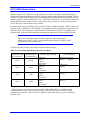
^ USER MANUAL 1 ^2 Accessory 85M ^3 MACRO INTERFACE FOR YASKAWA SIGMA-V ^4 3Ax-603928-xUxx ^5 December 14, 2012 Single Source Machine Control Power // Flexibility // Ease of Use 21314 Lassen Street Chatsworth, CA 91311 // Tel. (818) 998-2095 Fax. (818) 998-7807 // www.deltatau.com Copyright Information © 2011 Delta Tau Data Systems, Inc. All rights reserved. This document is furnished for the customers of Delta Tau Data Systems, Inc. Other uses are unauthorized without written permission of Delta Tau Data Systems, Inc. Information contained in this manual may be updated from time-to-time due to product improvements, etc., and may not conform in every respect to former issues. To report errors or inconsistencies, call or email: Delta Tau Data Systems, Inc. Technical Support Phone: (818) 717-5656 Fax: (818) 998-7807 Email: [email protected] Website: http://www.deltatau.com Operating Conditions All Delta Tau Data Systems, Inc. motion controller products, accessories, and amplifiers contain static sensitive components that can be damaged by incorrect handling. When installing or handling Delta Tau Data Systems, Inc. products, avoid contact with highly insulated materials. Only qualified personnel should be allowed to handle this equipment. We expect our products to be protected from hazardous or conductive materials and/or environments that could cause harm to the product by damaging components or causing electrical shorts. When our products are used in an industrial environment, install them into an industrial electrical cabinet or industrial PC to protect them from excessive or corrosive moisture, abnormal ambient temperatures, and conductive materials. If Delta Tau Data Systems, Inc. products are directly exposed to hazardous or conductive materials and/or environments, we cannot guarantee their operation. REVISION HISTORY REV. 0 1 2 3 DESCRIPTION Manual pre-release Formatted for publishing Different homing instructions added Added additional note about MI20 bit 0 setting in relation with Ultralite encoder conversion table setup DATE CHG APPVD 3/30/2011 4/17/2011 6/8/2011 J.S S.S S.S J.SCHATZ S. SATTARI S. SATTARI 12/14/12 S.S S. SATTARI Accessory 85M Table of Contents INTRODUCTION .................................................................................................................................................. 1 GETTING STARTED............................................................................................................................................ 2 Setup of Yaskawa Drive ....................................................................................................................................... 2 Useful Parameters Inside SGDV SIGMA-V Drive ............................................................................................. 2 ACC-85M Hardware Setup................................................................................................................................... 3 SW1 Slave Node Selector ................................................................................................................................. 3 SW2 Master IC Selector ................................................................................................................................... 3 ACC-85M Software Setup .................................................................................................................................... 4 MACRO Ring Order Method ............................................................................................................................ 5 Rotary Switch Address Setting .......................................................................................................................... 7 Turbo PMAC Ultralite/UMAC PMAC Motor Setup .......................................................................................... 8 SECONDARY ENCODER .................................................................................................................................. 11 Secondary Encoder Setup on ACC-85M ............................................................................................................. 11 DIGITAL I/O ....................................................................................................................................................... 13 Flag inputs ......................................................................................................................................................... 13 General Purpose Output...................................................................................................................................... 15 High Speed TTL Output ..................................................................................................................................... 15 DISPLAYS............................................................................................................................................................ 18 Link Status LED................................................................................................................................................. 18 MODULE STATUS LED .................................................................................................................................. 18 ACC-85M Faults Displayed on Yaskawa SERVOPACK .................................................................................... 18 SPECIAL MI-VARIABLES FOR MACRO INTERFACE................................................................................. 20 MONITOR PARAMETER TABLE .................................................................................................................... 22 CONNECTOR PINOUTS .................................................................................................................................... 24 SC-Style Fiber Interface Connector – MACRO Comms (OPT-A) ....................................................................... 24 RJ-45 In and Out Interface Connector – MACRO Comms (OPT-C) .................................................................... 24 Connector J2 – Interface Signals for Accessory card .......................................................................................... 24 Connector J2 Diagram................................................................................................................................... 24 User Inputs Circuit Diagram.......................................................................................................................... 25 User Output Circuit Diagram......................................................................................................................... 25 High Speed TTL Outputs Circuit Diagram...................................................................................................... 25 Table of Contents i Accessory 85M INTRODUCTION The MACRO SIGMA-V Application Module (ACC-85M) is an accessory card that connects to the Yaskawa Sigma-V (SGDV) amplifier. The purpose of this accessory card is to provide the MACRO fieldbus interface between Yaskawa Corp. amplifiers and Delta Tau Data Systems MACRO-based motion controllers. This interface accessory card provides 2 outputs, one that is Open-collector style and another dedicated to higher speed triggered output that is Open-collector style and limited to 5V operation. This interface card also has 3 inputs that operate from 8-24Vdc. A 15-pin high density DSUB connector is used for the user’s interface. This accessory card requires the user to supply an external 12-24Vdc power supply for the I/O interfaces. It should be noted that there are two types of SGDV amplifier. When specifying the Servopack be sure to request the “COMMAND OPTION ATTACHABLE TYPE”. This Servopack has an external port connector that is used for peripheral devices. Contact Yaskawa for further information on exchanging amplifiers. J 2 J 2 O U T O U T I N I N Figure 1: ACC-85M with OPT-A Figure 2: ACC-85M with OPT-C Fiber Optic MACRO Copper MACRO 1 Accessory 85M Getting Started Setup of Yaskawa Drive Perform the installation and setup of the SGDV SIGMA-V drive “Command Option Attachable Type” per the recommendations of Yaskawa Corp. This should include the electrical installation of the motor and the drive per the instruction manual supplied with the Yaskawa SIGMA-V drive. You may use the SIGMAWIN setup program (provided by Yaskawa Corp.) to set up the drive’s parameters, or enter parameters using the operator interface on the front of the SIGMA-V drive. Since the SERVOPACK with Option Module is expecting an option module, if powered up without the ACC-85M connected to the drive, an error code will be generated (A.E70: Error of Command-Option Module not Detected) which should be cleared using the SIGMAWIN software. Once ACC-85M is connected and mounted in place, it can be detected by SERVOPACK and viewed in SIGMAWIN software. Figure 3: Product Information Window in SIGMAWIN software Refer to the Appendix B in the SIGMA-V User’s Manual for the list of parameters. Useful Parameters Inside SGDV SIGMA-V Drive There are a few parameter settings in the drive that, if known, will make the setup of the ACC-85M and motor interface easier. They are listed in the following table: Table 1: Useful Parameters in SIGMA V SERVOPACK PARAMETER Pn002.2 Pn20E Pn210 Pn50A Pn50B 2 NOTES Set this value for the incremental use of an absolute encoder. Useful to consider when an encoder error A.810 occurs and the MTURN CLR (Fn008) does not work. If an absolute encoder is used that has no battery, you may encounter this issue. Set Pn002 = x1xx when this issue occurs. These are encoder feedback gearing. A 20-bit encoder should return 1,048,576 counts per revolution when these values are set to 1. The factory default for these values is set to divide by resulting in lower resolution accessible through MACRO. It is recommended that these are set to 1 for better servo performance. These values are used to establish position overtravel limits. To bypass the limits set Pn50A = 8xxx (P-OT) and Pn50B = xxx8 (N-OT). Accessory 85M There are also parameters available to bypass wired functions such as SERVO ENABLE , POSITIVE OVERTRAVEL, and NEGATIVE OVERTRAVEL. Refer to Pn50A and Pn50B for setting these overrides. WARNING If the values of overrides are set to bypass the physical interface at the CN1 connector on the drive, dangerous over-travel or undesired motion may occur. Caution must be used when operating the drive with any overrides enabled To implement the incremental use of an absolute encoder, configure PN002.2 = 1. This is sometimes necessary if there is an absolute encoder used where there is no backup battery. Gearing may be implemented by setting the parameters Pn20E and Pn210. Setting both of these to 1 will make a 20-bit encoder provide 1,048,576 counts per revolution which provides better performance both in velocity and torque mode control. ACC-85M Hardware Setup ACC-85M is designed to provide MACRO communication to Yaskawa Sigma V SERVOPACK drives. Each ACC-85M can be configured to use either a single servo node on the MACRO ring or one servo node and its corresponding IO node. This selection is done through rotary switches SW1 and SW2. SW1 Slave Node Selector Rotary switch SW1 determines which nodes are enabled on the ACC-85M station. If SW1 is set to E (14), Ring Order Method can be used to setup the node and master number of the station. If SW1 is set to F (15), default MI variables will be loaded upon power up. Table 2: MI996 Settings for Various Node Selections SW1 0 1 2 3 4 5 6 7 8 9 10 11 12 13 14 15 MI996 Value $0F1FE20 $0F1FE31 $0F3FE20 $0F3FE31 $0F1FE64 $0F1FE75 $0F3FE64 $0F3FE75 $0F1FEA8 $0F1FEB9 $0F3FEA8 $0F3FEB9 $0F1FE2C $0F1FE3D $0F0FE10 $0F1FE1B Nodes Enabled 0 1 0,2 1,3 4 5 4,6 5,7 8 9 8,10 9,11 12 13 None (S/W Macro Ring Order Setup) 11 (Set MI variables to factory default) SW2 Master IC Selector Rotary switch SW2 determines which Master number the station gets bind to. Setting SW1 to E(14) will set the station for Ring Order Method and setting of SW2 will not be used. 3 Accessory 85M ACC-85M Software Setup Software setup for ACC-85M can vary depending on users choice of using SW1 and SW2 settings for defining the binding MACRO master and active nodes or setting it through Ring Order Method. If SW1 is set to E (14), then Ring Order Setup will be used and MACRO ASCII communication should be used to setup the parameters and communication in ACC-85M. If SW1 and SW2 are set such that they define the binding MACRO master number and servo node, manual setup is preferred. Usually replacing a unit is easier if the setup is done using the rotary switches. In either method, note that The Phase clock in the ACC-85M is defaulted to 10kHz ( MI992=5000 ) and the Servo clock is defaulted to 2 kHz ( MI998=4 ). Depending on required MACRO communication rate, defined by Phase clock frequency on Ultralite/UMAC, different Servo Clock Divider (MI998) values should be used to provide synchronized data communication between ACC-85M and SERVOPACK. NOTE Higher Servo frequencies allow for better compliance when tuning motors. Although the default is 2 kHz, we recommend trying to operate at 4 kHz or 8 kHz for best results in servo performance. The following table provides some samples of phase clocking settings: Table 3: Clock Settings Depending on Desired Servo Rates Desired ACC-85M Servo Frequency 1 2 kHz 4 kHz 8 kHz 8 kHz 1 MACRO Comm. Freq.(PhaseFreq.) 10 kHz 8 kHz 8 kHz 16 kHz Ultralite / UMAC Settings I6800=5895 I6801=0 I6802=4 I10=4193067 I6800=7371 I6801=0 I6802=1 I10=2097067 I6800=7371 I6801=0 I6802=0 I10=1048533 I6800=3684 I6801=0 I6802=1 I10=1048320 ACC-85M Settings MI992=5000 (default) MI998=4 (default) MI992=6250 MI998=1 MI992=6250 MI998=0 MI992=3125 MI998=1 SERVO frequency must be set to operate at 1KHz, 2KHz, 4KHz, 8KHz, or 16KHz for proper synchronization of cyclical data between the amplifier and the UMAC motion controller. Other combinations are possible. Refer to the Ixxxx and Mixxx parameters in their respective manuals for alternate values. 4 Accessory 85M MACRO Ring Order Method In PMAC Executive PRO2 version 4.2.12.0 or newer, MACRO Ring ASCII setup (accessible through Configure Menu) can be utilized to setup the ACC-85M over the MACRO ring. Figure 4: MACRO RING ASCII Window; Controller Setup In this setup assistant page, follow these steps (for detailed explanation on all the parameters, refer to Turbo PMAC Software Reference Manual) 1. Set proper values to I6800, I6801, I6802 (based upon the table in previous page) to get proper clock settings on the Ultralite/UMAC. 2. Set I6840 to $4070 to set the MACRO IC 0 as synchronizing master. 3. Set I6841 to $FC001 or appropriate value to enable the required nodes. 4. Set I70 and I71 to corresponding values to resemble servo nodes enabled on I6841. 5. Set I78 to 32 for Master/Slave communication timeout. 6. Click Save Changes. (Respond No to the question about saving the parameters on stations) 7. Once saving is finished, click Setup Ring Controller button (Select No in response to a pop-up question of issuing a $$$*** to the controller). This will set proper values for I80, I81, and I82. 8. Click Save Changes. (Respond Yes to the question about saving the parameters on stations) 9. Click Reinit. MACRO Ring button. 10. Click Detect MACRO Ring button. 5 Accessory 85M 11. After completion of step 9, you should be able to see a list of all your MACRO stations under the drop-down list called “Stations Detected” and they ate automatically numbered from 1, starting from the station downstream of the Ultralite/UMAC. 12. Select the station number for ACC-85M. The data shown under “Detailed Description” should match your hardware. Figure 5: MACRO RING ASCII Window; Station Setup 13. Setup MI992 and MI998 based upon table 3. 14. Setup MI995 to default value of $4080. 15. Setup MI996 based upon table 2. (First Nibble Represents the Master Number) 16. Set proper values for MI8, MI9 and MI10. (refer to uMACRO manual for detailed information) 17. Click Save Changes button and request that changes only be saved on selected station. 18. Repeat steps 12 to 17 for all stations. 19. Power Cycle the station so ACC-85M and SERVOPACK synchronize.. If you get an A.E00 error on the drive display, check the MI20 and MI21 settings on ACC-85M. MI20 and MI21 should be set less than or equal to MI998 setting. Once updated, save and reset the station. Once all the stations are setup, user should continue with Turbo PMAC Ultralite/UMAC Motor Setup Section. 6 Accessory 85M Rotary Switch Address Setting In this method, the node number must be established in the ACC-85M by setting the addressing switches. Refer to Hardware Setup section for configuration detailed on switch settings and their corresponding nodes. Connect the MACRO ring between the Ultralite/UMAC and all stations and follow these steps to setup the MACRO ring: 1. Select the Phase and Servo clock based upon table 3 and setup I6800 (I6850/I6900/I6950), I6801 (I6851/I6901/I6951), I6802 (I6852/I6902/I6952) and I10 accordingly. (Note: if there are more than 1 master IC, corresponding clock setting I-variables has to be modified to reflect the same clock settings on all master ICs) 2. Setup I6840 to $4030 to make the first IC the synchronizing ring controller. I6890/I6940/I6990 if available should be set to $10. ($90 if the ICs are not on sharing phase and servo clocks through hardware such as bus or backplane) 3. Setup I6841/I6891/I6941/I6991 to enable the nodes desired. The nodes enabled should match the node settings on ACC-85M(s) based upon their rotary switch settings. 4. Set I70/I72/I74/I76 and I71/I73/I75/I79 according to I6841/I6891/I6941/I6991 settings. These will enable Node Auxiliary Registers and sets the Node Protocol Type Control. 5. Set I78 and I79 to 32. 6. Set I80, I81 and I82 depending on the clock settings and related calculations explained in detail in Turbo Software Reference manual. (This step is optional if user wants to enable automatic ring error check) 7. Save the settings on Ultralite/UMAC by issuing a SAVE command and reset the controller by issuing a $$$ command. Up to this point the controller is setup and ready to communicate on the MACRO ring. The rest of the setup is for each station and has to be repeated for each station. During setup, it would be a good idea to have the Global Status window, accessible through View menu, open to keep an eye on MACRO errors. MACRO errors can be cleared using CLRF (clears errors on MACRO controller) and MSCLRFn (clears MACRO errors on station with node number n). 8. Setup MI992 based upon table 3. (The MI-variables can be set by using MACROSLAVE commands or MS commands. For example MS0,MI992=3125 will set MI992 to 3125 and to query a MI-variable send command as MS0,MI992 and the response will be the value which MI992 is holding.) 9. Issue a save on the station using MACROSLAVESAVEn command. (MSSAVEn will save the parameters on station with node n enabled.) 10. Reset the station using the MACROSLAVE$$$n command. (MS$$$n will reset the station with node n enabled) 11. Setup MI998 based upon table 3. 12. Issue a save on the station using MSSAVEn command. 13. Reset the station using the MS$$$n command. 14. Power Cycle the station so ACC-85M and SERVOPACK synchronize. 15. Setup MI20 and MI21 according to uMACRO manual. (MI20 and MI21 should be set less than or equal to MI998 setting. Once updated, save and reset the station.) Steps 8 to 15 have to be repeated for all stations. Once all the stations are setup, user should continue with Turbo PMAC Ultralite/UMAC Motor Setup Section. 7 Accessory 85M Turbo PMAC Ultralite/UMAC PMAC Motor Setup Once the ACC-85M is setup, by default it will transmit the encoder position over MACRO ring through the assigned node and receives the commands on the same node. The following setting are general guidelines for setting up a motor in PMAC and other detailed settings can be done based upon Turbo PMAC Software Reference manual and uMACRO Software Reference Manual. Encoder Conversion Table Setup (I8000..8191 / Ixx03 / Ixx04) The encoder position is reported back on MACRO ring every phase clock, but the data is only updated between SERVOPACK and ACC-85M every servo cycle defined by MI992 and MI998 settings. This data has to be read by Encoder Conversion Table (ECT) in PMAC before it can be used as position/velocity feedback. NOTE In Yaskawa Sigma V SERVOPACK, gearing may be implemented by setting the parameters Pn20E and Pn210. Default setting for these parameters, will result in ¼ of actual encoder position reporting on MACRO ring. Setting both of these to 1 will provide full resolution to Turbo PMAC Ultralite/UMAC, This provides better performance both in velocity and torque mode control. For reading the primary feedback from ACC-85M, Yaskawa motor feedback, conversion type $2 has to be used. This conversion method is a two line entry in ECT and can be done either though I-variable setting or Encoder Conversion Table Setup tool accessible through Configure menu of PEWIN32PRO2. First line of the entry specifies which node the position data is located. Table 4: Encoder Conversion Table 1st line Setting for Primary Feedback Register MACRO IC 0 Node 0 MACRO IC 0 Node 1 MACRO IC 0 Node 4 MACRO IC 0 Node 5 MACRO IC 0 Node 8 MACRO IC 0 Node 9 MACRO IC 0 Node 12 MACRO IC 0 Node 13 MACRO IC 1 Node 0 MACRO IC 1 Node 1 MACRO IC 1 Node 4 MACRO IC 1 Node 5 MACRO IC 1 Node 8 MACRO IC 1 Node 9 MACRO IC 1 Node 12 MACRO IC 1 Node 13 Reg. 0 Reg. 0 Reg. 0 Reg. 0 Reg. 0 Reg. 0 Reg. 0 Reg. 0 Reg. 0 Reg. 0 Reg. 0 Reg. 0 Reg. 0 Reg. 0 Reg. 0 Reg. 0 First Line Value $2F8420 $2F8424 $2F8428 $2F842C $2F8430 $2F8434 $2F8438 $2F843C $2F9420 $2F9424 $2F9428 $2F942C $2F9430 $2F9434 $2F9438 $2F943C Register MACRO IC 2 Node 0 MACRO IC 2 Node 1 MACRO IC 2 Node 4 MACRO IC 2 Node 5 MACRO IC 2 Node 8 MACRO IC 2 Node 9 MACRO IC 2 Node 12 MACRO IC 2 Node 13 MACRO IC 3 Node 0 MACRO IC 3 Node 1 MACRO IC 3 Node 4 MACRO IC 3 Node 5 MACRO IC 3 Node 8 MACRO IC 3 Node 9 MACRO IC 3 Node 12 MACRO IC 3 Node 13 Reg. 0 Reg. 0 Reg. 0 Reg. 0 Reg. 0 Reg. 0 Reg. 0 Reg. 0 Reg. 0 Reg. 0 Reg. 0 Reg. 0 Reg. 0 Reg. 0 Reg. 0 Reg. 0 First Line Value $2FA420 $2FA424 $2FA428 $2FA42C $2FA430 $2FA434 $2FA438 $2FA43C $2FB420 $2FB424 $2FB428 $2FB42C $2FB430 $2FB434 $2FB438 $2FB43C Note that the bit-19 mode switch has been set to 1 so that the data out of the MACRO node is not shifted. This changes the second hex digit from 7 to F. Type 1 MACRO feedback comes with fractional count information in the low five bits, so it does not need to be shifted. (Default setting of MI20 bit 0 to a value of 0 on ACC-85M will provide 5 bits of left shift to send all feedback resolution as whole counts to MACRO controller. With the default setting, there is no need for additional shift on the Ultralite side, so bit 19 of the encoder conversion table is set to 1, disabling the shifting. If the MI20 bit 0 is set to 1, then 8 Accessory 85M the position is not shifted on the ACC-85M before it gets transmitted over MACRO and the data needs to be shifted on the Ultralite side, by setting bit 19 of the first line of encoder conversion table entry to 0.) The second line of an entry for MACRO feedback should be $018000 to specify the use of 24 bits ($018) starting at bit 0 ($000). Once the encoder conversion table entry is ready, Ix03 and Ix04 of the desired PMAC motor has to point to the address of the second line which holds the processed data. For example, for an ACC-85M which is on node 0 and motor 1, I8000=$2F8420, I8001=$018000 and I103=$3502 and I104=$3502. For complete list of addresses for each encoder conversion table line, please refer to Turbo Software Reference Manual. Command Output Address (Ixx02) Command output is addressed by Ixx02 setting in PMAC and Table 5 shows different settings for Ixx02 based upon the node selection on ACC-85M Table 5: Command Output Address for MACRO Nodes Register MACRO IC 0 Node 0 MACRO IC 0 Node 1 MACRO IC 0 Node 4 MACRO IC 0 Node 5 MACRO IC 0 Node 8 MACRO IC 0 Node 9 MACRO IC 0 Node 12 MACRO IC 0 Node 13 MACRO IC 1 Node 0 MACRO IC 1 Node 1 MACRO IC 1 Node 4 MACRO IC 1 Node 5 MACRO IC 1 Node 8 MACRO IC 1 Node 9 MACRO IC 1 Node 12 MACRO IC 1 Node 13 Reg. 0 Reg. 0 Reg. 0 Reg. 0 Reg. 0 Reg. 0 Reg. 0 Reg. 0 Reg. 0 Reg. 0 Reg. 0 Reg. 0 Reg. 0 Reg. 0 Reg. 0 Reg. 0 Ixx02 Setting $078420 $078424 $078428 $07842C $078430 $078434 $078438 $07843C $079420 $079424 $079428 $07942C $079430 $079434 $079438 $07943C Register MACRO IC 2 Node 0 MACRO IC 2 Node 1 MACRO IC 2 Node 4 MACRO IC 2 Node 5 MACRO IC 2 Node 8 MACRO IC 2 Node 9 MACRO IC 2 Node 12 MACRO IC 2 Node 13 MACRO IC 3 Node 0 MACRO IC 3 Node 1 MACRO IC 3 Node 4 MACRO IC 3 Node 5 MACRO IC 3 Node 8 MACRO IC 3 Node 9 MACRO IC 3 Node 12 MACRO IC 3 Node 13 Reg. 0 Reg. 0 Reg. 0 Reg. 0 Reg. 0 Reg. 0 Reg. 0 Reg. 0 Reg. 0 Reg. 0 Reg. 0 Reg. 0 Reg. 0 Reg. 0 Reg. 0 Reg. 0 Ixx02 Setting $07A420 $07A424 $07A428 $07A42C $07A430 $07A434 $07A438 $07A43C $07B420 $07B424 $07B428 $07B42C $07B430 $07B434 $07B438 $07B43C Motor Flag Address (Ixx25) Ixx25 tells Turbo PMAC what registers it will access for its position-capture flags, and possibly its overtravel-limit input flags and amplifier enable/fault flags, for Motor xx. Ixx25 Addresses for MACRO Flag Holding Registers are listed in Table 6. Table 6: Addresses for MACRO Flag Holding Registers IC Node # 0 1 4 5 8 9 12 13 MACRO IC 1 $003440 $003441 $003444 $003445 $003448 $003449 $00344C $00344D 9 MACRO IC 2 $003450 $003451 $003454 $003455 $003458 $003459 $00345C $00345D MACRO IC 3 $003460 $003461 $003464 $003465 $003468 $003469 $00346C $00346D MACRO IC 4 $003470 $003471 $003474 $003475 $003478 $003479 $00347C $00347D Notes MACRO Flag Register Sets 0, 16, 32, 48 MACRO Flag Register Sets 1, 17, 33, 49 MACRO Flag Register Sets 4, 20, 36, 52 MACRO Flag Register Sets 5, 21, 37, 53 MACRO Flag Register Sets 8, 24, 40, 56 MACRO Flag Register Sets 9, 25, 41, 57 MACRO Flag Register Sets 12, 28, 44, 60 MACRO Flag Register Sets 13, 29, 45, 61 Accessory 85M Motor Flag Mode Control (Ixx24) Motor flag mode control specifies how the flag information in the registers specified by Ixx25, Ixx42, and Ixx43 is used. Ixx24 is a set of 24 individual control bits and the following figure summarizes the functionality for each of these bits. Ixx24 Motor xx Flag Mode Control Flag Register Type Reserved for Future Use Reserved for Future Use Reserved for Future Use Capture with High-Resolution Feedback Error Saturation Control Sub-Count Capture Enable Continue on Desired Position Limit Amplifier Enable Use Desired Position Limit Enable Overtravel Limit Use MACRO Node Use for Amp & Capture Flags Amplifier Fault Use Action-on-Fault Amplifier-Fault Polarity 23 22 21 20 19 18 17 16 15 14 13 12 11 10 9 8 7 6 5 4 3 2 1 0 Figure 6: Ixx24 Motor xx Flag Mode Control Setting Ixx24 for SERVOPACK with ACC-85M requires the following bits to be set appropriately: - Bit 0: flag registers are in PMAC2-style Servo IC format. This bit has to be set high. - Bit 17: Overtravel limit Use: If the overtravel limits are wired to SERVOPACK drive and they are enabled through SERVOPACK parameters Pn50A.3 and Pn50B.0, both SERVOPACK and Turbo PMAC Ultralite/UMAC will take action upon overtravel condition which causes a conflict in control. If use of overtravel limits are required, a set of overtravel inputs are provided on J2 connector of ACC-85M and by setting bits 2 and 3 of MI23, ACC-85M will transfer these inputs as positive and negative overtravel limits over MACRO ring. If overtravel limits are to be disabled, set this bit high. - Bits 18 and 19: Since all amplifier enable, amplifier fault and capture flags are transferred over MACRO ring, bit 18 is 1 and bit 19 is 0. - Bit 23: Since Yaskawa Sigma V SERVOPACK has a high true fault (it reports a 1 when indicating a fault condition), this bit should be set to 1. For example if overtravel limits are not being used, Ixx24=$860001 and if overtravel limits are wired to J2 on ACC-85M, MI23=$C and Ixx24=$840001. Power-On Servo Position Setup (Ixx10/Ixx95) If Yaskawa Sigma V motor connected to SERVOPACK has absolute encoder, the absolute position can be read through ACC-85M by setting proper values to motor xx power-on servo position address (Ixx10) and motor xx power-on servo position format (Ixx95). Default setting for bit 2 of MI20 on ACC-85M, will transfer the non-cyclic absolute position data returned as received, which means it will send the LSB of the absolute position as bit 0 of the MI920 which matches the cyclic position feedback resolution. 10 Accessory 85M NOTE Setting up automatic reading of absolute servo position over MACRO ring (Bit 3 of Ixx80 = 0 ) is NOT recommended since power up sequence and timing between SERVOPACK and Turbo PMAC Ultralite/UMAC becomes important. Instead, it is suggested that Ixx80 is set to 4, disabling automatic read of absolute position upon power-up/reset of controller and a #n$* command in initialization PLC is used after possible MACRO errors are cleared first using CLRF and MSCLRFn commands. Failure to read the absolute position upon power-up, can cause PMAC to become unresponsive to ASCII communications with the host pc. The following table shows the required values of Ixx10 for all of the MACRO nodes that can be used. Table 7: MACRO Absolute Position Read Ixx10 Settings MACRO Node Number 0 1 4 5 8 9 12 13 Ixx10 for MACRO IC 0 $000100 $000001 $000004 $000005 $000008 $000009 $00000C $00000D Ixx10 for MACRO IC 1 $000010 $000011 $000014 $000015 $000018 $000019 $00001C $00001D Ixx10 for MACRO IC 2 $000020 $000021 $000024 $000025 $000028 $000029 $00002C $00002D Ixx10 for MACRO IC 3 $000030 $000031 $000034 $000035 $000038 $000039 $00003C $00003D Ixx95 specifies how the absolute power-on servo-position data, if any, for Motor xx is interpreted. Setting Ixx95 to a value of $740000 will result in an unsigned interpretation of absolute position reported from SERVOPACK and ACC-85M. In contrast a setting value of $F40000 will interpret the data as signed value. Tuning and Running the Motor Depending on command mode selection on the drive (MI30) velocity or torque (default) mode, as explained in special mi- parameters for ACC-85M, tuning should be performed just like any other PMAC motor. PMAC Tuning PRO2 software can be used for this purpose. Secondary Encoder ACC-85M provides a convenient solution for adding a secondary encoder to the system, which can be used a position feedback or a general handwheel input. This input supports the following input formats: - Quadrature (A-Quad-B) - Pulse and direction - Pulse up/pulse down - Hall format (UVW) Secondary Encoder Setup on ACC-85M ACC-85M supports multiple formats of feedback on J2 connector. MI910 determines the format and positive direction of the encoder feedback. Please refer to connector pin out section of the manual for detailed information on wiring instructions. Refer to uMACRO Software Reference for the settings of MI910. The other registers in the accessory are set to default values to allow a quadrature encoder to operate. 11 Accessory 85M Once the encoder feedback in interpreted by ACC-85M, MI23 determines how this data should be transferred to Turbo PMAC Ultralite/UMAC over MACRO ring. This data can be sent over the MACRO ring in two formats, depending on bit 0 and bit 1 of MI23. If bit 0 of MI23 is set to 1, the cyclic secondary position data is returned in registers 1 and 2 servo node as two 16 bit words. In this mode the data has 8 bits of 1/T sub-count resolution. There is no automatic full support for this format of data in Turbo PMAC Ultralite/UMAC encoder conversion table settings. MACRO Servo Node 23 Register 0 Register 1 Register 2 Cyclic Primary Feedback Data from Yaskawa Sigma V SERVOPACK Cyclic Secondary Feedback Data 16 LSB Cyclic Secondary Feedback Data 16 MSB 22 21 20 19 18 17 16 15 14 13 12 11 10 9 8 7 6 5 4 3 2 1 0 23 22 21 20 19 18 17 16 15 14 13 12 11 10 9 8 7 6 5 4 3 2 1 0 23 22 21 20 19 18 17 16 15 14 13 12 11 10 9 8 Register 3 7 6 5 Flags 4 3 2 1 0 23 22 21 20 19 18 17 16 15 14 13 12 11 10 9 8 7 6 5 4 3 2 1 0 Figure 7: Cyclic Secondary Feedback Format with MI23=1 If bit 1 of MI23 is set to 1, the cyclic secondary position data is returned register 0 of the corresponding IO node. This IO node has to be enabled using switch SW1 or MI996 setting. In this mode the data has 5 bits of sub-count resolution. MACRO Servo Node Register 0 23 22 21 20 19 18 17 16 15 14 13 12 11 10 MACRO I/O Node Register 1 Cyclic Primary Feedback Data from Yaskawa Sigma V SERVOPACK 9 8 7 6 5 Blank 4 3 2 1 0 Register 0 9 8 23 22 21 20 19 18 17 16 15 14 13 12 11 10 7 6 5 8 7 6 5 4 3 2 1 0 3 2 1 0 23 22 21 20 19 18 17 16 15 14 13 12 11 10 23 22 21 20 19 18 17 16 15 14 13 12 11 10 Flags 9 8 7 6 5 4 3 2 1 0 23 22 21 20 19 18 17 16 15 14 13 12 11 10 Register 2 Blank 4 Register 3 Blank 9 Register 1 Cyclic Secondary Feedback Data from ACC-85M J2 connector 23 22 21 20 19 18 17 16 15 14 13 12 11 10 Register 2 8 7 6 5 4 3 2 1 0 23 22 21 20 19 18 17 16 15 14 13 12 11 10 8 7 6 5 4 3 2 1 0 7 6 5 4 3 2 1 0 Register 3 Blank 9 9 Blank 9 8 7 6 5 4 3 2 1 0 23 22 21 20 19 18 17 16 15 14 13 12 11 10 9 8 Figure 8: Cyclic Secondary Feedback Format with MI23=2 To input the register 0 of MACRO IO node to PMAC motor registers, the encoder conversion table conversion type $6, Parallel Y/X-word data with no filtering, should be used. First line of the entry specifies which node the secondary position data is located. Table 8: Encoder Conversion Table 1st line Setting for Secondary Feedback Register MACRO IC 0 Node 2 MACRO IC 0 Node 3 MACRO IC 0 Node 6 MACRO IC 0 Node 7 MACRO IC 0 Node 10 MACRO IC 0 Node 11 MACRO IC 1 Node 2 MACRO IC 1 Node 3 MACRO IC 1 Node 6 MACRO IC 1 Node 7 MACRO IC 1 Node 10 MACRO IC 1 Node 11 Reg. 0 Reg. 0 Reg. 0 Reg. 0 Reg. 0 Reg. 0 Reg. 0 Reg. 0 Reg. 0 Reg. 0 Reg. 0 Reg. 0 First Line Value $6F8420 $6F8424 $6F8428 $6F842C $6F8430 $6F8434 $6F9420 $6F9424 $6F9428 $6F942C $6F9430 $6F9434 Register MACRO IC 2 Node 2 MACRO IC 2 Node 3 MACRO IC 2 Node 6 MACRO IC 2 Node 7 MACRO IC 2 Node 10 MACRO IC 2 Node 11 MACRO IC 3 Node 2 MACRO IC 3 Node 3 MACRO IC 3 Node 6 MACRO IC 3 Node 7 MACRO IC 3 Node 10 MACRO IC 3 Node 11 Reg. 0 Reg. 0 Reg. 0 Reg. 0 Reg. 0 Reg. 0 Reg. 0 Reg. 0 Reg. 0 Reg. 0 Reg. 0 Reg. 0 First Line Value $6FA420 $6FA424 $6FA428 $6FA42C $6FA430 $6FA434 $6FB420 $6FB424 $6FB428 $6FB42C $6FB430 $6FB434 Note that the bit-19 mode switch has been set to 1 so that the data out of the MACRO node is not shifted. This changes the second hex digit from 7 to F. Secondary feedback on register 0 of MACRO IO node matches type 1 MACRO feedback, which comes with fractional count information in the low five bits, 12 Accessory 85M hence it does not need to be shifted. Default setting 0 for bit 2 of MI23, provides 5 bits of fractional count for cyclic secondary feedback. The second line of an entry for secondary feedback on MACRO IO node must be set to $018018 to specify the use of 24 bits ($018) starting at bit 24 ($018) on the X/Y word. Once the encoder conversion table entry is ready, Ix03 of the desired PMAC motor has to point to the address of the second line which holds the processed data if this feedback is a position feedback for the motor (load feedback). For quadrature encoders, hardware checks for proper state transition between quadrature states and indicates an error in pattern by setting bit 30 of channel status word (MI938) to high. Digital I/O ACC-85M has multiple inputs and output pins available for user: - - - 3 opto-coupled inputs Positive over-travel flag input (Normally closed) Negative over-travel flag input (Normally closed) Home flag input Note that these inputs can be used as general purpose inputs if required by user. 8 – 24VDC support Both sinking and sourcing inputs are possible (dependent of user wiring) 1 opto-coupled, open collector output 8 – 24VDC support 200 mA max current Both sinking and sourcing output is possible (dependent of user wiring) 1 high speed TTL sinking output (not opto-coupled, EQU) 300 mA max current Flag inputs 3 opto-coupled inputs can be either used as general purpose input, in which case their status is available on bits 8, 9 and 10 of MI938, or they can be used as over-travel and home flags by setting bits 3 and 4 of MI23 to 1, which reports in input states as over-travel and capture bits in register 3 of MACRO servo node. Table 9: ACC-85M Inputs and addressing Input Pin J2-4 J2-14 J2-9 GPIO Use MI938, bit8 MI938, bit 9 MI938, bit 10 Flags Use Home Flag (MI23 bit 4 set to 1) Positive Over-travel Flag (MI23 bit 3 set to 1) Negative Over-travel Flag (MI23 bit 3 set to 1) Important Note on Using the Flags Over travel limits on J2 can be utilized by setting bit 3 of MI23 to 1 and enabling the over-travel limits in Ixx24 in PMAC (set bit 17 of Ixx24 to 0). However, use of home flag requires extra attention. If the cyclic primary feedback (Yaskawa motor feedback) is being used for both position and velocity feedback of the motor, but user wants to use a home or over-travel flag for establishing a position reference, then following setting has to be implemented: 13 Accessory 85M Homing based upon the index pulse of Yaskawa motor (Hardware Capture): MSn,MI23=$0 Ixx97=0 // // // // n: Servo Bit 5=0: xx: PMAC Hardware Node Number Get Home Capture Position from Primary Source motor number position capture is possible Homing based upon the Home Flag wired to J2 (Software Capture): MSn,MI23=$20 Ixx97=1 MSn,MI912=2 MSn,MI913=0 // // // // // // // // n: Servo Node Number Bit 5=1: Get Home Capture Position from Secondary Source xx: PMAC motor number Software position capture required since the captured position in MI921 is from secondary feedback source a setting of 2 or 10 defines trigger level of capture flag Low to high or high to low Select home flag as capture flag Homing based upon the Home Flag wired to J2 (Software Capture): MSn,MI23=$20 Ixx97=1 MSn,MI912=2 MSn,MI913=1 Ixx24=$860001 // // // // // // // // // // // n: Servo Node Number Bit 5=1: Get Home Capture Position from Secondary Source xx: PMAC motor number Software position capture required since the captured position in MI921 is from secondary feedback source a setting of 2 or 10 defines trigger level of capture flag Low to high or high to low Setting of 1 or 2 for Selecting Pos/Neg flag as capture flag Setting bit 17 of Ix24 disables the over-travel limit function on PMAC motor allowing homing based upon a limit flag only necessary if bit 3 of MI23 is set to 1 If cyclic secondary feedback (encoder connected to J2 on ACC-85M) is used for position feedback and primary feedback (Yaskawa SERVOPACK encoder) is used for velocity feedback, the following setup has to be implemented: Homing based upon index pulse of your position encoder wired to J2 (Hardware Capture): MSn,MI23=$2 Ixx97=0 MSn,MI912=1 // // // // // // // n: Servo Node Number Bit 1=1: Cyclic Secondary Position Data is returned in IO Node 24 bit registers 0 Bit 5=1: Get Home Capture Position from Secondary Source xx: PMAC motor number Hardware position capture is possible Position capture based upon the index pulse of secondary encoder Homing based upon home flag wired to J2 (Hardware Capture): MSn,MI23=$22 Ixx97=0 MSn,MI912=2 MSn,MI913=0 14 // // // // // // // // // n: Servo Node Number Bit 1=1: Cyclic Secondary Position Data is returned in IO Node 24 bit registers 0 Bit 5=1: Get Home Capture Position from Secondary Source xx: PMAC motor number Hardware position capture is possible a setting of 2 or 10 defines trigger level of capture flag Low high or high low (or any combination with index signal) Select home flag as capture flag Accessory 85M Homing based upon limit flags wired to J2 (Hardware Capture): MSn,MI23=$22 // // // // // // // // // // Ixx97=0 MSn,MI912=2 MSn,MI913=1 Ixx24=$860001 n: Servo Node Number Bit 5=1: Get Home Capture Position from Secondary Source xx: PMAC motor number Hardware position capture is possible a setting of 2 or 10 defines trigger level of capture flag Low high or high low (or any combination with index signal) Setting of 1 or 2 for Selecting Pos/Neg flag as capture flag Setting bit 17 of Ix24 disables the over-travel limit function on PMAC motor allowing homing based upon a limit flag only necessary if bit 3 of MI23 is set to 1 General Purpose Output There is one opto-coupled, open collector output available on ACC-85M which is connected to GPIO00. This output can be used as sinking or sourcing as shown in following diagrams: 8 to 24VDC Supply 8 to 24VDC Supply D0_COM 0 5 15 5 15 DO1 10 10 DO1 4 14 4 14 9 9 3 13 3 13 8 8 Load 200 mA Max Load 200 mA Max 2 12 2 12 7 7 1 11 1 11 6 6 GND Figure 9: Sourcing Output GND Figure 10: Sinking Output To enable the GPIO00 as output, bit 0 of MI936 should be set to 1 and saved. The status of output can be controlled by writing to bit 0 of MI935. High Speed TTL Output On J2 connector of ACC-85M, there is also one output (not opto-coupled) that is connected to position compare circuitry output (EQU) that operates at high speed based upon secondary encoder. To use position compare feature on ACC-85M, parameters MI925, MI926 and MI927 has to be set. Position compare circuitry, compares the position of secondary encoder with values in position compare registers A and B, MI925 and MI926, and turns the EQU output on/off upon detection of the edge. In addition, the position compare circuitry is capable of automatically incrementing the edges to produce a pulse train dependent on secondary position. This auto-increment period can be defined using MI928. There are two methods for defining the auto-increment: 1. The pulse train starts around the actual phase captured position of secondary encoder. 2. The pulse train starts further away from actual position of secondary encoder. This is usually desired for applications where the pulse output has to start once the speed is constant. To setup the pulses around the current position, user has to “bracket” the current position between the compare values A and B. 15 Accessory 85M Position Compare Value A (MI925) 12 bits of subcount resolution Phase Capture Position (MI931) 8 bits of subcount resolution Position Compare Value B (MI926) 12 bits of subcount resolution Position Compare Auto-increment (MI927) 12 bits of subcount resolution Figure 11: EQU Method 1, “Bracketing” the Actual Position In this method, the value for MI925, MI926 and MI927 has to be written without any modification to MI928 or MI929. In this method once each edge is detected, the state of EQU output toggles and autoincrement value will be added or subtracted from the other compare value depending on the direction of travel. In second method, the value for edges A (MI925) and B (MI926) and auto-increment (MI927) are setup on one side of present actual position and initial states of EQU is set by writing to MI929 and toggling MI928. Position Compare Value B (MI926) 12 bits of subcount resolution Position Compare Value A (MI925) 12 bits of subcount resolution Phase Capture Position (MI931) 8 bits of subcount resolution Position Compare Auto-increment (MI927) 12 bits of subcount resolution Figure 12: EQU Method 2, Pulse Generation with Distant Starting Position In this method, toggling the MI928 flags the circuit not to auto-increment for first edge detection, allowing the actual position to be “bracketed” between the edges A and B, and from that point, acts as method 1, whenever the actual position reaches one of the edges, it adds/subtracts auto-increment value to/from other compare value. 16 Accessory 85M NOTE Position compare values A (MI925) and B (MI926) and position compare autoincrement (MI927) value have 12 bits of 1/T sub-count resolution in contrast to phase captured position register (MI931) which has 8 bits of 1/T sub-count resolution. Since usually the values of position compare A and B are setup based upon the present actual position, it is important to remember the scale factor of 16 between the data source (MI931) and target (MI925, MI926 and MI927) NOTE Position compare auto-increment (MI927) value has 12 bits of 1/T sub-count resolution, but in order for circuit to work consistently, the minimum possible value is equal to 2049, representing a 1/4096 count more than half a count. 17 Accessory 85M DISPLAYS All indicators appear at the front panel of this accessory card. Module Status J 2 Link Status O U T I N Figure 13: ACC-85M Status Indicators Link Status LED The green LED illuminates when the MACRO signal is present. The red LED is lit when the MACRO signal is not present. This provides a quick check for received signal from device located immediately upstream from ACC-85M on MACRO ring. MODULE STATUS LED This green LED illuminates to indicate that the module is operating correctly in the ACC-85M. This indicator flashes when the module is in the MACRO-ASCII mode. Table 10: Module Status LED Descriptions GREEN LED Off Blink On Off Blink On RED LED Off Off Off On On Blink Status Description No ring activity. No Failure. Module is in ASCII Mode. No failure Module operating normally. No failure No ring activity. Hard Failure (may need to cycle power) No ring activity. Hard failure (may need to cycle power) Module has resettable error (try CLRF to clear error) ACC-85M Faults Displayed on Yaskawa SERVOPACK The following table, lists the codes which are displayed on Yaskawa SERVOPACK 7-segment display upon detection of a fault in ACC-85M option module. These faults are cleared if the MACRO Master sends a command to clear the faults (“CLRF” or “MSCLRFn”). Error code 0EA0 requires a power cycle to clear. If after a “CLRF” the fault still exists, the Yaskawa SERVOPACK display will show the fault code again. 18 Accessory 85M Table 11: ACC-85M Faults Displayed on Yaskawa SERVOPACK CODE 0A0B DESCRIPTION MACRO Ring Break 0A0D Ring Data Fault Prior ring station transmitting a RING BREAK Duplicate station node address error. Command option module alarm Amplifier Watchdog error Checksum Error (memory transfer error) AMP not enabling 0A0F 0EA0 0EA2 0EA3 0EA4 19 NOTES Check the physical MACRO ring connection Not enough SYNC packets or too many data packet errors. Check MI8, MI9 and MI10 settings Check the device upstream of ACC-85M for any errors Check MI996 of all stations versus I6841 of controller Must cycle power to clear. Amplifier not responding to ACC-85M option module. DPRAM checksum error from amplifier. ENA timeout error. Check Yaskawa SERVOPACK. Accessory 85M Special mi-Variables for macro interface The following MI-variables are specifically designed for the uMACRO interface associated with the Yaskawa SGDV SERVOPACK Command Option ACC-85M. Table 13: Special MI-Variables For Macro Interface MIVAR MI30 MI31 MI32 MI33 MI34 MI35 MI36 MI37 MI38 MI39 MI40 MI41 MI42 MI43 MI44 MI45 MI46 MI47 MI48 MI49 MI50 MI51 MI52 MI53 MI54 MI55 MI56 MI57 MI58 20 DESCRIPTION DEFAULT Control Mode Select (2:Speed Control 3: Torque Control) P/PI toggle Request (V_PPISel) CLR Request for position integration (ClrPosIntg) Select bank (gain) parameter (BankSel) Sensor on request (SensOn) Magnetic pole detection start request (PolDet) Break signal release request (BrkRelease) (2-bits) D0 - Positive torque limit enabled D1 - Negative torque limit enabled (2-bits) D0 – Positive software overtravel D1 – Negative software overtravel Encoder Latch (Latch) 8-bits D0 SelEncCphs Select C phase latch position encoder D1 SelEncExt1 Select latch position encoder Ext1 D2 SelEncExt2 Select latch position encoder Ext2 D3 SelEncExt3 Select latch position encoder Ext3 D4 RqCPhs Latch request of C phase input position D5 RqExtSig1 Latch request of Ext1 input position D6 RqExtSig2 Latch request of Ext2 input position D7 RqExtSig3 Latch request of Ext3 input position Reserved Select Monitor 1 (MonSel1) (8-bit address) (Sets MI920 monitor value) Select Monitor 2 (MonSel2) (8-bit address) (Sets MI921 LSB monitor Value) Select Monitor 3 (MonSel3) (8-bit address) (Sets MI921 MSB monitor Value) Select Monitor 4 (MonSel4) (8-bit address) (uses monitor table values) Select Monitor 5 (MonSel5) (8-bit address) Select Monitor 6 (MonSel6) (8-bit address) Select Monitor 7 (MonSel7) (8-bit address) Select Monitor 8 (MonSel8) (8-bit address) Reserved FB position counter (FbPosition) Monitor Data 1 Monitor Data 2 Monitor Data 3 Monitor Data 4 Monitor Data 5 Monitor Data 6 Monitor Data 7 Monitor Data 8 2 SAVED PARAM * 1 * * 00 * 00 * 1 0 0 0 1 0 0 0 * $30 (HM) * $0E (ABS) * $0F (ABS) * $3B (Alarms) * * * * * Accessory 85M Control Status (16-bit) D1-D0 SELMOD MI59 MI60 MI61 MI62 MI63 MI64 MI65 MI66 MI67 MI68 Not a MIxx parameter Located in MACRO node flag register (reg. 3) MI69 0: Cntrl Disabled 1:Position 2:Speed 3:Torque Positioning completed Motor rotating/traveling Velocity reached Speed being clamped Torque being clamped Motor drive state of option card Safety stop state D2 COIN D3 MotMoving D4 ReachVelCmd D5 SpdClamped D6 TrqClamped D7 OpEnabled D8 SafetyStop D9-D15 Not defined Sequence Status (16-bit) D0 Alarm Alarm status D1 Warning Warning status D2 AlmRstComp Alarm reset completed D3 D4 SvOnComp Servo-on completed D5 SensOnComp Sensor-on completed D6 PolDetComp Magnetic pole detection completed D7 BrkReleased Break is released D8 MainPowerOn Main circuit power-on D9 SvReady Servo ready D10-D15 Not defined SelMon1 Select Monitor 1 SelMon2 Select Monitor 2 SelMon3 Select Monitor 3 SelMon4 Select Monitor 4 SelMon5 Select Monitor 5 SelMon6 Select Monitor 6 SelMon7 Select Monitor 7 SelMon8 Select Monitor 8 Latch Status (8 LSBs) D0 CPhsRqLvl C phase latch request level D1 ExtSig1RqLvl Ext1 Latch request level D2 ExtSig2RqLvl Ext2 Latch request level D3 ExtSig2RqLvl Ext3 Latch request level D4 CphsComp C phase latch completed D5 ExtSig1Comp Ext1 latch completed D6 ExtSig2Comp Ext2 latch completed D7 ExtSig3Comp Ext3 latch completed Input Signals (8 MSBs) MACRO node flag bit DEC Input DEC signal status D16 P_OT Input P-OT signal status D17 N_OT Input N-OT signal status D18 EXT1 Input EXT1 signal status D19 EXT2 Input EXT2 signal status D20 EXT3 Input EXT3 signal status D21 HBB Input HBB signal status D22 not defined D23 21 Accessory 85M MONITOR PARAMETER TABLE The following tables list the parameters which may be assigned to the MI41 – MI48 variables. Table 14: High Speed Parameter Table (Cyclical Values) MonSel Code 00h 01h Motor FB Speed Reference Speed Command 02h Reference Torque Command 03h 04h 0Ah 0Bh 0Ch 0Dh 0Eh 0Fh 30h 31h 32h 33h 34h 35h 36h 37h 38h 39h 3Ah Position Error ( last 32 bits) Position Error ( first 32 bits) PG Count data (last 32 bits) PG Count data (first 32 bits) FPG Count data (last 32 bits) FPG Count data (first 32 bits) FB Position (last 32 bits) FB Position (first 32 bits) C-Phase latch position (last 32 bits) C-Phase latch position (first 32 bits) EXT1 Latch position (last 32 bits) EXT1 Latch position (first 32 bits) EXT2 Latch position (last 32 bits) EXT2 Latch position (first 32 bits) EXT3 Latch position (last 32 bits) EXT3 Latch position (first 32 bits) Virtual position error 3Bh 22 FUNCTION UNITS OS/1000000h OS/1000000h max torque / 1000000h Reference Unit Reference Unit Reference Unit Reference Unit Reference Unit Reference Unit Reference Unit Reference Unit Reference Unit Reference Unit Reference Unit Reference Unit Reference Unit Reference Unit Reference Unit Reference Unit Reference Unit COMMENTS (Unused mode) for Position control (Unused mode) for Position control Motor PG Position Motor PG Position Fully Closed PG Position Fully Closed PG Position Input Signal State BitNo D0 D1 D2 D3 D4 D5 D6 D7 D8 – D23 Name SI0 SI1 SI2 SI3 SI4 SI5 SI6 SI7 - D24 HWBB1 D25 HWBB2 D26 D27 D28 D29 D30 D31 STOP1 STOP2 STOP3 STOP4 EDM2 EDM3 Alarm/Warning Code SI0 Port input SI1 Port input SI2 Port input SI3 Port input SI4 Port input SI5 Port input SI6 Port input SI7 Port input Reserved Hardwired Base Block Input 1 Hardwired Base Block Input 2 Safety Option Card Inp1 Safety Option Card Inp2 Safety Option Card Inp3 Safety Option Card Inp4 Safety Option Card Out2 Safety Option Card Out3 SI0 – 7: Open(H) : 1 Close(L) : 0 STOP 1 – 4: EDM 2 – 3: HWBB 1 – 2: Open(H) : 1 Close(L) : 0 STOP1~4, EDM2 and EDM3 are effective only when Safety option card is connected to servo unit. Alarm Code (Last 16 bits) Warning Code (First 16 bits) Accessory 85M Table 15: Low Speed Parameter Table (Non-Cyclical Values) MonSel Code FUNCTION UNITS COMMENTS -1 10h Actual Speed 11h Commanded Speed (Speed control) 12h 13h 14h 15h 16h Internal Torque Command Number of pulses from origin Angle from origin point Input Signal Monitor Output Signal Monitor 17h Speed (Set by position command) 18h 19h 1Ah 1Bh 1Ch 1Dh 1Eh 22h Position Command Error Counter Accumulated Load Factor Regenerative Load Factor DB Resistance Power Consumption Input Command Pulse Counter Feedback Pulse Counter Fully-Closed Feedback Pulse Cntr Total Work Time Multi-turn data of absolute encoder after “Sensor On” request Initial Incremental PG Count Position data of absolute encoder after “Sensor On” (last 32 bits) Position data of absolute encoder after “Sensor On” (forst 32 bits) 23h 24h 25h 26h 23 Rotary (min ) Linear (mm/s) Rotary (min-1) Linear (mm/s) % Pulse Deg Un000 Un001 Un002 Un003 Un004 Un005 Un006 Rotary (min-1) Linear (mm/s) Reference Unit % % % Pulse Pulse Pulse 100mS Un008 Un009 Un00A Un00B Un00C Un00D Un00E Un012 Rotation Rotary Motor Only Pulse Rotary Motor Only Scaling Unit Linear Motor Only Scaling Unit Linear Motor Only Un007 Accessory 85M CONNECTOR PINOUTS All interface signals appear at the front panel of this accessory card. SC-Style Fiber Interface Connector – MACRO Comms (OPT-A) This is the fiber optic MACRO interface connector. RJ-45 In and Out Interface Connector – MACRO Comms (OPT-C) These are the wired MACRO interface connector. Connector J2 – Interface Signals for Accessory card This is a high density DB15S DSUB connector. The user needs a to supply a mating connector. Pin# Signal Name Type 1 2 3 4 5 6 7 8 9 10 11 12 13 14 15 CHA+ CHB+ CHC+ HOME FL_RET CHACHBCHCIN_B DOUT EQU GND +5Vdc IN_A DO_COM INPUT INPUT INPUT INPUT INPUT INPUT INPUT INPUT INPUT Open Collector TTL POWER POWER INPUT Open Collector Return Description Secondary encoder input Secondary encoder input Secondary encoder input Flag_A RET for flags Secondary encoder input Secondary encoder input Secondary encoder input Flag_C User-defined output High Speed TTL output Digital Ground Encoder Power (supplied from accessory card) Flag_B User-defined output Return Connector J2 Diagram J2 16 CHA1+ CHA1EQ U_OUT CHB1+ CHB1G ND +5V CHC1+ CHC1HO ME1 IN_B IN_A FL_RT1 DO 1 D0_COM 1 6 11 2 7 12 3 8 13 4 9 14 5 10 15 17 DB15HD, RT A NGLE, PCB MNT 24 Accessory 85M User Inputs Circuit Diagram 1 3 5 7 U11 4 3 4 3 4 3 C1 E1 ACIN1 ACIN2 C1 E1 ACIN1 ACIN2 C1 E1 ACIN1 ACIN2 1 2 U12 1 2 1 3 5 7 U13 1 2 RP2 2 4 6 8 4.7K RP3 IN_B IN_A HO ME 1 FL_RT 1 2 4 6 8 8Vdc to 24Vd c Flags 4.7K RP4 1 3 5 7 C34 0.1UF 2 4 6 8 1K C35 C36 0.1UF 0.1UF User Output Circuit Diagram U14 ANA1 CAT1 C1 E1 4 3 1 Q2 MMBT3906L 3 1 2 DO1 3.3K 2 R49 D0_COM OPEN COLLEC TOR OUT PUT High Speed TTL Outputs Circuit Diagram 8 +5V U15A 1 EQU 3 4 2 GND 25 DS75452M EQU_OUT