1
electrolux e:line gas cooktops electrical connection 11
1. Remove the hotplate burners to access the hotplate
injectors. Replace the factory fitted NG injectors with the
appropriate injectors, as supplied (see Table 3).
2. Unscrew the hex nut from the regulator. The hex nut,
brass washer and nylon insert will disengage as an
assembly.
3. Unclip the nylon insert and nut assembly by rotating the
insert ¼ turn, and pulling it free.
4. Turn over the insert and clip back into position.
5. Refit the hex nut assembly to the regulator ensuring that
it is fully screwed down. The regulator is now set for
connection to LP.
6. Turn on the gas supply and at each new connection
check for leaks using soapy water: each hotplate valve
should be turned on, one at a time, and the injector
hole blanked off for several seconds.
7. The operation of the regulator can be confirmed by
connecting a manometer to the pressure test point
located on the side of the regulator body adjacent to
the outlet.
With the appliance operating check the outlet pressure
• when all burners of the appliance are operating
at maximum,
• when the smallest burner of the appliance is operating
at minimum.
Under these conditions the outlet pressure should not vary
from the nominal outlet pressure of 2.60kPa by more the
+/-0.52kPa.
8. If the regulator appears to not be performing
satisfactorily then check the following points.
• If the outlet pressure is consistently too low then the
inlet pressure may be too low and adjustment of an
upstream regulator may be needed, or an upstream
regulator or valve with insufficient flow capacity may
be present in the gas supply line. If this is suspected
then it may be necessary to repeat the checks whilst
measuring both the inlet and outlet pressure to
determine if the inlet pressure is in the range
2.75 – 7.00kPa.
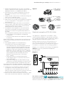
• Check that the insert has been fitted correctly
as per diagram figure 11. Check that the hex nut is
fully screwed down.
• Check that the regulator has been fitted to the gas
supply line in the correct orientation, the arrow on the
base of the body indicates the direction of gas flow.
Once these checks have been completed, if the regulator still
fails to perform in a satisfactory manner it should be replaced.
Hex nut
assembly, fully
screwed down
Figure 11
Hex nut assembly,
removed
from regulator
and insert
disassembled
Insert
oriented for
natural gas
operation
Insert
oriented
for LPG
operation
Electrical connection (220-240 Volts)
The appliance is supplied with a standard 7.5 Amp
service cord terminated by a 3-pin plug for connection
to a standard household socket. The electrical supply is
required to power the electronic ignition system.
NOTE! It will be necessary for servicing purposes to
disconnect the electrical power supply. The power
point should therefore be accessible after the appliance
is installed, as specified in the local wiring regulations.
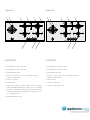
Diagram 1 is a schematic of the wiring in the appliance.
WEIGHT of the unit is printed on the appliance
packaging label.
Diagram 1
9. One by one, turn the knobs to minimum and screw
in the bypass screw (accessible when the knob is
removed) until a small stable flame results. Turn the
knob to maximum and then back to minimum to ensure
that the correct minimum flame is maintained.
10.Attach the LPG sticker to the cooker, near the gas supply
inlet. Cover the Natural Gas label that is factory fitted.
Use of hose assemblies
Ensure that the hose assembly is restrained from accidental
contact with the flue outlet of an underbench oven or any
other hot surface of an adjacent appliance.