1
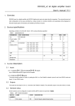
DDX320_v2 all digital amplifier board User’s manual 1. Overview DDX320 board is a digital amplifier with S/PDIF digital audio input and output directly to speakers. The volume/channel and other configuration can be easy controlled by a rotary encoder or a remote controller, and value/state will be displayed on the LED module panel. All functions is handled by the MCU on board. 2. Electrical specifications Operating conditions Vcc=DC 28V, Tamb = 25°C unless otherwise specified Table1. Specifications list PARAMETER TEST CONDITIONS MIN TYP UNIT MAX Vcc AC (dual rail) 12 20 26 V (Power supply DC 15 28 36 V voltage) Po 2.0 channel (Output power) Woofer RL = 8Ω, VCC = 35 V 75 W RL = 6Ω, VCC = 36 V 100 W RL = 4Ω, VCC = 30V 65 W RL = 8Ω, VCC = 35 V 80 W RL = 4Ω, VCC = 35V 160 W 100 dB SNR SR 32 192 kHz Sample rate Resolution 24 bit 3. Function Description 3.1 Inputs 3.1.1 Coaxial (CH-1, 2) and Optical(CH-3, 4) inputs Up to 192kHz/24bit S/PDIF signal can be accepted. 3.1.2 External (CH-5~8)inputs The board accept another 4x inputs, by setting the SW-1 on. See Table2 for details. Inputs 5 and 6 are S/PDIF mode and Inputs 7~8 are CMOS mode. 3.2 Outputs The output can be setup for 2.0 or 2.1 channel. See Table2 for details. The subwoofer output is not active when 2.0 mode. 3.3 Hardware setup Some functions can be configured or switch on/off by DIP-4 switch on board list in Table2. Table2. SWITCH NUMBER DIP- 4 switch description NAME STATE DESCRIPTION 1 8/4 x inputs 2 ON Up to 8 inputs, external inputs active OFF Up to 4 inputs ON Display auto off after 5sec OFF Display always keep on ON Output 2.0 mode OFF Output 2.1 mode Not used, should be put ON Test mode, not used in OFF mode OFF Normal Display dimming 3 2.0/2.1 output mode 4 3.4 Display and Control 3.4.1 display. DDX320 use a 4 digital 7-segment LED display. The LED will display volume/channel/EQ/bass volume and bass crossover frequency. LED will be auto off when DIP-4 switches set to OFF(details in Table2). 3.4.2 Control by rotary encoder(we call it EC in short below) Volume adjustment: turn the EC to left or right to control volume down or up. Channel switching: press the EC button to control the channel switch from CH1 to CH3 by cycling. Standby/Wake-up: press the EC button up to 3 sec to enter the standby mode or back to active(ON) state. 3.4.3 Control by a remote controller The remote control functions list in table3. Table3. Remote key functions Key name function Display POWER Enter the standby or wake up . for stand by MUTE Mute enter/exit --- , when mute VOL+/VOL- Volume increase/decrease CH+/CH- Channel switch up/down EQ Preset EQ: E-xx E--- =EQ bypass (x means value, same as below) E-00=EQ Flat E-01= Flat E-02 =Rock E-03 =Soft Rock E-04=Jazz E-05 =Classical E-06 =Dance E-07=Pop E-08 =Soft E-09 =Hard E-10 =Party E-11 =Vocal E-12 =Hip-Hop E-13 =Dialog E-14 =Bass-Boost #1 E-15=Bass-Boost #2 E-16 =Bass-Boost #3 MODE Setup the crossover frequency 000 = pass through 080 = 80Hz etc (range from 80 to 360hz) xxx MIX Switch the left and right channel on output 1-2 or 2-1 DFT Restore the default configuration DFT TONE Enter /exit bass volume mode B-xx F1 Checking EQ F2 Checking Channel number F3 Adjust the brightness of display 4. Installation PCB Size: 135*105mm 5. Q&A