1
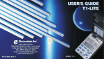
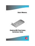
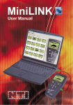
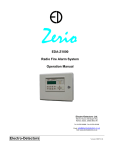
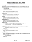
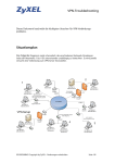
Introducing
A Handheld T1 Testing Pair from T-COM
00
.
$ 795
T-COM is proud to announce two new additions to
its family of fine telecommunications testing
products, the Model 314A ARBITRATOR and the Model
324A VALIDATOR Hand Held test sets.
Taking advantage of the latest integrated circuit and
manufacturing technology, we are able to bring you these two
feature packed, light weight, rugged instruments at surprisingly
low prices. The design of both of these test sets follow the
T-COM tradition of reliability, accuracy and ease of use. Now
you can have a T-COM quality tester with you at all times.
Model 314A
The Model 314A ARBITRATOR is intended for use by both the
layman and the expert troubleshooter and is ideally suited for the
installer. The layman can readily isolate the source of T1
problems among several potential sources, such as the service
provider, in house wiring and user equipment. The expert
trouble shooter can further isolate a T1 problem to the
cause of problem and pinpoint the likely trouble maker.
ARBITRATOR
T1 Compliance Monitor
00
5.
$2,39
The Model 324A VALIDATOR is intended for use by service
technicians to qualify and maintain a variety of DS1
transmission systems and equipment. It has all the essential
features needed by the service technician to reliably
perform his tasks, including testing the latest technology
HDSL transmission systems. Like all T-COM products
the VALIDATOR has a clear, intuitive user interface
that requires minimum training for effective use.
Both instruments are the most cost and weight
effective on the market today. They can
withstand the rigors of outside plant use
while performing sophisticated testing
with the minimum of operator controls.
Ask your T-COM sales representative
for a demonstration. We are
confident you will be delighted
with these products.
Model 324A
VALIDATOR
T1/DS0 Analyzer
with HDSL Loop Codes
About the VALIDATOR
The T-COM Model 324A VALIDATOR is a low cost ($2,395 complete), light weight (only 1lb-10oz.), hand held test
set designed to provide all the essential capabilities a test technician needs to reliably qualify and maintain and
troubleshoot a variety of DS1 transmission systems and equipment, in the CO, the outside plant, or in customers'
premises.
The VALIDATOR contains a DS1 receiver providing real-time impairment diagnostics, with dedicated LED's, on any
DS1 signal observed when patched to DSX-1 access jacks (OUT or monitor) or bridged across a T1 line. The receiver
provides level and frequency measurement of the T1 signal; it can also indicate bit slippage if a clock signal or another
T1 signal is supplied to the reference receiver. At the press of a key the reciever provides comprehensive impairment
statistics. The receiver automatically recognizes the framing format (NONE, D4, ESF, SLC-96) of the monitored
signal. It also automatically identifies the test pattern presented. These features, not only contribute in simplifying the
operation of the set, they also make it foolproof.
The Validator receiver displays the frequency and level of selected DS0 channels. Signaling Types, ROBBED BIT
and CCIS, are operator selectable. Signaling Bits A, B, C, and D are displayed for a selected DS0 channel and selected
Signaling Type.
The VALIDATOR transmitter can deliver a variety of standard test patterns to stress and qualify a T1 transmission
system. The transmitter can also be used for sending various loop codes (CSU, NIU4, NIU5, PYLD, NTWK LINE,
T.4/92, and PairGain HiGain).
The receiver and the transmitter can be used completely independently or in combination. When used independently,
the receiver can monitor, for example, an ESF 3/24 pattern, while the transmitter delivers an ESF QRSS pattern.
The VALIDATOR transmitters can inject single logic bit errors or a 1-4 logic bit error rate.
The VALIDATOR can transmit and obtain pattern sync on a variety of BERT PATTERNS including QRSS, 1 IN 8, 2
IN 8, 3 IN 24, ALL ZEROS, ALL ONES, 1:1, NET55, OCT55, and DALY55. A user can select any of these patterns for
transmission. Selecting a transmission pattern has no effect on the receiver, which continuously attempts to obtain
Frame and Pattern signatures.
The VALIDATOR illuminates LED's indicating received signal status and history. These LED's include SIGNAL
PRESENT, SIGNAL PRESENT HISTORY, FRAMING (NONE, D4, ESF, SLC-96), AMI and B8ZS LINE CODING,
B8ZS HISTORY, PATTERN SYNC (QRSS, 1 IN 8, 2 IN 8, 3 IN 24, ALL ZEROS, ALL ONES, 1:1, NET55, OCT55, and
DALY55) , OUT OF FRAME, OUT OF FRAME HISTORY, BLUE ALARM (AIS), BLUE ALARM (AIS) HISTORY,
ONES DENSITY, ONES DENSITY HISTORY, EXCESS ZEROS, EXCESS ZEROS HISTORY, YELLOW ALARM,
YELLOW ALARM HISTORY, PATTERN SYNC LOSS HISTORY and DS1 IDLE, DS1 IDLE HISTORY.
The VALIDATOR displays test results on eight, seven segment LED displays. Results displayed include CLOCK
SLIPS, BIT, BPV, FRAME, CRC, DS1 FREQ and LEVEL, DS0 FREQ and LEVEL, and ERRORED SECONDS errors.
The VALIDATOR is powered by (3) 1.2V, 3.8A hr NiMH batteries providing approximately 6 hours of continuous
operation. An AC-DC Power Adapter is provided for simultaneous operation and battery recharge.
..
..
The VALIDATOR is supplied with the following items:
A/C Power Adapter
Two bantam-to-bantam cables
User's Manual
Carrying/storage case
Rx
Tx
REF
OFF ON 12VDC
RED-CHARGING
GREEN-MAINT.
Model 324A
Top
(detail)
Actual
Size
Applications
DSI Bit Slippage and Jitter Checking
Channel
Bank
or
Digital
Switch
When patching the VALIDATOR REF T1 receiver to a T1 timing source,
or utilizing the internal 1.544 MHz oscillator, while the RX T1 receiver is
patched to a MONITOR jack or bridged across a T1 line, the VALIDATOR
can display CLOCK SLIPS. CLOCK SLIPS are calculated as:
CLOCK SLIPS = REF clock pulses - RX clock pulses counted.
By observing the slippage one can readily access whether timing is lost or
jitter is present on the system. This test can be carried-out on any live circuit
without causing any interference.
DSX-1
MON
REF T1
TIMING
SOURCE
ERROR
VALIDATOR
DISPLAY
Model 324A
BIT ERRS
BPV ERRS
FRM ERRS
CRC ERRS
Signaling Type
DS1 FREQ
DS1 LEVEL
Channel
ROBBED BIT
DS0 FREQ
DS0 LEVEL
CCIS
ERROR SEC
Signaling Bits
CLK SLIPS
A
B
C
Battery
LOW BATTERY
D
Error Inject
Data Bits
RESULTS
LOGIC
1 2 3 4 5 6 7 8
Pattern
Rx Status
AMI
QRSS
B8ZS
1 IN 8
SIGNAL PRESENT
2 IN 8
OUT OF FRAME
3 IN 24
BLUE ALARM (AIS)
ALL 0'S
ONES DENSITY
ALL 1'S
EXCESS ZEROS
1 : 1
YELLOW ALARM
NET55
DS1 IDLE SIGNAL
OCT55
PATTERN SYNC LOSS
History
RESTART
DALY55
TX
RX
Loop Codes
Line Code
STD
T.4/92
AMI
B8ZS
PROP
EXT
INT
TX
Frame
Tx Clk Source
RX
Looping CSU's and NI's
NONE
D4
ESF
LOOP UP LOOP DN
Receive
SEND
SLC96
Pre
Loop
RX
TX
VALIDATOR
When patched to a T1 office repeater, the VALIDATOR can send and detect loop
commands to selectively loop NIU's (NIU4, NIU5, NTWK (ESF)), and CSU's (LINE (D4,
ESF) and PYLD (ESF)).
LINE
REPEATERS
Office
Repeater
NI
DSX-1
ERROR
VALIDATOR
DISPLAY
CSU
VALIDATOR
DISPLAY
ERROR
Model 324A
BIT ERRS
Model 324A
BIT ERRS
BPV ERRS
BPV ERRS
FRM ERRS
FRM ERRS
CRC ERRS
CRC ERRS
Signaling Type
DS1 FREQ
DS1 LEVEL
Channel
A
B
C
T1 Transmission System Qualification
Battery
LOW BATTERY
D
Error Inject
Data Bits
LOGIC
1 2 3 4 5 6 7 8
A
LOGIC
TX
RX
Loop Codes
Line Code
AMI
STD
T.4/92
B8ZS
PROP
TX
Frame
EXT
INT
NONE
D4
ESF
LOOP UP LOOP DN
Receive
SLC96
Pre
Loop
TX
RX
VALIDATOR
Bit Error Rate Testing can be performed from the CO or the Customer premise
location by either looping the other end (as above) or by using a test set at both
ends of the transmission system. This second approach offers the advantage of
letting one identify the direction in which a fault exits. An extensive family of
test patterns is provided to stress the transmission system.
SLLU
ERROR
Pattern
Rx Status
1 : 1
NET55
OCT55
DALY55
Tx Clk Source
Error Inject
QRSS
B8ZS
ALL 0'S
ALL 1'S
YELLOW ALARM
DS1 IDLE SIGNAL
PATTERN SYNC LOSS
History
RESTART
Battery
LOW BATTERY
D
AMI
2 IN 8
3 IN 24
ONES DENSITY
EXCESS ZEROS
C
Data Bits
1 IN 8
SIGNAL PRESENT
OUT OF FRAME
BLUE ALARM (AIS)
B
1 2 3 4 5 6 7 8
QRSS
B8ZS
SEND
Signaling Bits
CLK SLIPS
RESULTS
Pattern
Rx Status
AMI
RX
CCIS
ERROR SEC
Signaling Bits
CLK SLIPS
VALIDATOR
DISPLAY
Model 324A
BIT ERRS
BPV ERRS
FRM ERRS
CRC ERRS
Signaling Type
DS1 FREQ
DS1 LEVEL
Channel
DBL2
DBL1
SLRU
HDSL Looping and Transmission Testing
ERROR SEC
A
B
LOGIC
Pattern
Rx Status
AMI
QRSS
B8ZS
1 IN 8
SIGNAL PRESENT
2 IN 8
OUT OF FRAME
3 IN 24
BLUE ALARM (AIS)
ALL 0'S
ONES DENSITY
ALL 1'S
EXCESS ZEROS
1 : 1
YELLOW ALARM
NET55
DS1 IDLE SIGNAL
OCT55
PATTERN SYNC LOSS
History
RESTART
DALY55
TX
RX
Loop Codes
Line Code
STD
T.4/92
AMI
B8ZS
PROP
EXT
INT
TX
Frame
Tx Clk Source
RX
NONE
D4
ESF
LOOP UP LOOP DN
Receive
SEND
SLC96
Pre
Loop
T.4/92
RX
TX
VALIDATOR
AMI
B8ZS
PROP
TX
Frame
NONE
D4
ESF
Receive
SLC96
Pre
Loop
SEND
RX
TX
VALIDATOR
ERROR
VALIDATOR
DISPLAY
CRC ERRS
Signaling Type
DS1 FREQ
Channel
ROBBED BIT
CCIS
Signaling Bits
A
The VALIDATOR generates T1E1.4/92, PROP-PairGain HiGain, and
ADTRAN loop commands for testing HDSL transmission systems. Each
element of the HDSL transmission system can be selectively looped to isolate
failures to a particular system element. Looping can be implemented from either
end or stress patterns can be generated from both ends of the system for through
mode transmission testing.
Model 324A
BIT ERRS
BPV ERRS
FRM ERRS
CLK SLIPS
Battery
Error Inject
Line Code
STD
EXT
INT
LOOP UP LOOP DN
LOW BATTERY
D
Data Bits
TX
RX
Loop Codes
ERROR SEC
C
1 : 1
NET55
OCT55
DALY55
Tx Clk Source
RX
DS0 FREQ
1 2 3 4 5 6 7 8
ALL 0'S
ALL 1'S
YELLOW ALARM
DS1 IDLE SIGNAL
PATTERN SYNC LOSS
History
RESTART
DS1 LEVEL
Signaling Bits
CLK SLIPS
2 IN 8
3 IN 24
ONES DENSITY
EXCESS ZEROS
DS0 LEVEL
CCIS
RESULTS
1 IN 8
SIGNAL PRESENT
OUT OF FRAME
BLUE ALARM (AIS)
CSU
ROBBED BIT
DS0 FREQ
DS0 LEVEL
Channel
ROBBED BIT
DS0 FREQ
DS0 LEVEL
CCIS
RESULTS
Signaling Type
DS1 FREQ
DS1 LEVEL
ROBBED BIT
DS0 FREQ
DS0 LEVEL
ERROR SEC
B
C
Battery
LOW BATTERY
D
Error Inject
Data Bits
RESULTS
LOGIC
1 2 3 4 5 6 7 8
Pattern
Rx Status
AMI
QRSS
B8ZS
1 IN 8
SIGNAL PRESENT
2 IN 8
OUT OF FRAME
3 IN 24
BLUE ALARM (AIS)
ALL 0'S
ONES DENSITY
ALL 1'S
EXCESS ZEROS
1 : 1
YELLOW ALARM
NET55
DS1 IDLE SIGNAL
OCT55
PATTERN SYNC LOSS
History
RESTART
DALY55
TX
RX
Loop Codes
Line Code
STD
T.4/92
AMI
B8ZS
PROP
EXT
INT
TX
Frame
Tx Clk Source
RX
NONE
D4
ESF
LOOP UP LOOP DN
Receive
SEND
SLC96
Pre
Loop
RX
TX
VALIDATOR
Specifications
314A
Input
Range:
Line Code:
Impedance
6-36dB
AMI and B8ZS
>1000 W, Bridge
100 W, Terminate
100 W, Monitor
Indicators
Display LED's
BPV, Frame, CRC6, DS1 Frequency, DS1
Level (dBSX and volts)
Frame Format
NONE, D4, ESF, SLC96
Alarms
BPV, FRAME, CRC6, DS1 Frequency,
Low Battery
ALARMS with History
Signal Present, Out of Frame, Blue Alarm
(AIS), Ones Density (T1.403.1 1992) Excess
Zeros (>15 Zeros) Yellow Alarm
Results
Errors
DS1 FREQ Accuracy:
DS1 FREQ Resolution:
DS1 FREQ Range:
Line Level
DS1 Level Range:
BIT, BPV, Frame, CRC
± 5ppm 0º C to 40º C
1 Hz
1544000 ± 10000
+ 6 to -16dB ± 1dB
-16 to -40dB, ± 3dB
+ 6dB D to -40 DSX
SelfTest (On Power-Up)
“ErrCod 1” for an EPROM test failure
“ErrCod 2” for an SRAM test failure
“ErrCod 3” for an EPROM & SRAM test
failure
Physical
1.75" h, 5" w, 9" l
14 oz
Power
Batteries three 1.2V NiMH, 1.5Ahr
approx. 6 hours continuous operation
red LED = apprx. 30 min. remaining
Auxiliary Power
12 VDC, 400 mA
Environmental
32º to 122º F Operating
5º to 158º F Storage
95% max., non-condensing, Humidity
324A
Compatibility
ANSI T1.403, AT&T PUB62411
Primary T1 Receiver
Input Impedance Bridge >1000 W
Term = 100 W ± 5%
Monitor =100 W ± 5%
Range
Bridge = + 6 to -36dB
Term = + 6 to -36dB
Monitor = 100 W ± 5%
Tx and Rx Framing
NONE, D4, ESF, SLC 96
Tx and Rx Line Coding
AMI, B8ZS
Tx and Rx Patterns
QRSS, 1 IN 8, 2 IN 8, 3 IN 24, ALL
ZEROS, ALL ONES, 1:1, NET55,
OCT55, DALY55
(all Tx Patterns are frame aligned)
Status/History
B8ZS, Signal Present, Out-of-Frame,
Blue Alarm (AIS), Ones Density, Excess
Zeros, Yellow Alarm, DS1 Idle, Pattern
Sync Loss
DS0 Drop
Selected DSO channel to 8 data bit LED's
and speaker
DS0 Signaling Types
Robbed Bit, CCIS (Selectable)
Telecommunications Instrumentation
DS0 Signaling Bits
A, B, C, D
Reference T1 Receiver
Input Impedance 100 W ± 5%
Range
0 to -36dB
Compatibility
AT&T TA24/CB113
Transmitter Output
LBO
Fixed at 0 dBDSX
Tx Clock Source
Internal, derived from
received data, or external
DS0 FREQ Accuracy
DS0 LEVEL Accuracy
± 1.5Hz
± 0.2dBm
SelfTest (On Power-Up)
“ErrCod 1” for an EPROM test failure
“ErrCod 2” for an SRAM test failure
“ErrCod 3” for an EPROM & SRAM test
failure
Physical
1.75" h, 5" w, 9" l
1 lb 10oz.
Loop Codes
CSU, NIU4, NIU5, PAYLOAD (ESF),
NETWORK (ESF), LINE (D4), LINE
(ESF), T1E1.4/92 HDSL Maintenance,
Pairgain HIGAIN proprietary and
ADTRAN
Power
Batteries three 1.2V NiMH, 3.8Ahr
approx. 6 hours continuous operation
red LED = approx. 30 min. remaining
Auxiliary Power
12 VDC, 1000 mA
Results
Errors
Signal
Environmental
32º to 122º F Operating
5º to 158º F Storage
95% max., non-condensing, Humidity
BIT, BPV, FRAME, CRC, ERR SEC
DS1 FREQ, DS1 LEVEL, DS0
FREQ, DS0 LEVEL, CLOCK SLIPS
DS1 FREQ Accuracy
± 5ppm 0º to 40º C
DS1 FREQ Resolution 1Hz
DS1 FREQ Range
1544000 ± 10,000 Hz
DS1 LEVEL Accuracy (DSX)
+ 6 to -16dB, ± 1dB
-16 to -40dB ± 3dB
DS1 LEVEL Range
+ 6 to -40dB DSX
T-COM, LLC
445 Indio Way Sunnyvale, California 94086
Telephone: 408/523-9900
FAX: 408/523-9909
Email: [email protected]
www.tcomcorporation.com
Printed in USA 04/99