1
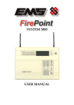
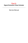
Zerio
EDA-Z1000
Radio Fire Alarm System
Operation Manual
Electro-Detectors Ltd.
Electro House, Edinburgh Way
Harlow, Essex, CM20 2EG UK
Tel: 01279 635668. Fax 01279 450185
Email: [email protected]
Web: www.electrodetectors.co.uk
Electro-Detectors
Version Z1000/V1.06
EDA-Z1000 - Operation Manual
Please note: No operator serviceable parts are contained within this panel. Always refer to a qualified technician
for parts and servicing.
This manual should be provided to the site’s nominated ‘responsible person’ and left on the premises
for easy reference.
Electro-Detectors
Version Z1000/V1.06
Page 2
EDA-Z1000 - Operation Manual
Revision History
Manual
Version
Author
Software
Version
Date
Description
V1.00
V1.01
DR
DR
0.08
0.10
01-10-05
01-11-05
V1.02
DR
0.10
22-12-05
V1.03
V1.04
V1.05
V1.06
SM
SM
SM
PP
0.15
1.01
1.02
1.06
13-06-06
14-03-07
18-02-08
02-02-10
First Release
Sounder Repeater Added to System, Access code override function and ability to view access codes, re-program
devices to factory settings, re-program unique Id. Antenna monitoring configuration added.
Must reset booster panel to ensure memory cleared. All other devices should also be reset on power up. Operation of
fire relays when silence / reset pressed
New features for disabling faults and Double knock functions.
New menu structure, Survey mode, function keys and sounder circuit
HMO software, antenna calibration option, add Text via the panel and contrast settings added
View Test Zones added
Electro-Detectors
Version Z1000/V1.06
Page 3
EDA-Z1000 - Operation Manual
Contents / Index
1.0
Introduction
2.0
Front Panel Display and Keys
3.0
User Operations
3.1
System Normal
3.2
Fault Conditions
3.3
To Silence a Fault
3.4
To Reset a Fault
3.5
Alarm Condition
3.6
To Silence Sounders
3.7
To Re-sound the Sounders
3.8
To Reset an Alarm
3.9
Menu Navigation
3.10
To Change Date and Time
3.11
To Isolate a Zone
3.12
To Isolate a Device
3.13
To Enable a Zone
3.14
To Enable a Device
3.15
View System History of Events
4.0
Advanced User Operations
4.1
General
4.2
To View Access Codes
4.3
Changing Access Codes
4.4
To Select a Test Mode
4.5
To Disable a Test Mode
4.6
To View Zones in Test
Electro-Detectors
Version Z1000/V1.06
Page 4
EDA-Z1000 - Operation Manual
1.
Introduction
Electro Detectors has been manufacturing radio fire alarm systems for over 16 years and has now complemented its range of
products with a smaller purpose built control panel , the Zerio system. It has been designed for smaller systems and is capable of
handling 99 devices in 8 zones. Typical installations could be small offices, private houses, HMO’s, guest houses and small hotels.
The system has been designed to allow very simple set up with most operations being automated.
The system is capable of displaying full text and having sophisticated cause and effect programming.
The panel requires a single 2.8Ahr Lead Acid battery to achieve 48 hours standby. Two 6V 4Ahr batteries connected in series will
provide a 72- hour HMO compliant standby.
Devices for the system are visually the same as the standard Millennium devices but are labelled differently with a yellow label. In
order to maintain compatibility, the Zerio panel can re-program a Millennium device to operate with the Zerio format, providing the
devices are version V1.6 or later.
A memory module is plugged into the processor board. This stores a copy of any set-up information including device text and cause
and effects. This can be used as a means of swapping data between panels should the need arise.
In order to log devices and program devices into the system, they need to be connected via a supplied programming lead. The
system also stores the data programmed into each device allowing replacement devices to be easily cloned onto the system.
Prior to installation, the building where the system is to be installed must be surveyed to ensure that each device to be fitted has a
good radio communication path to the control panel. If this is not done correctly the system will operate unreliably.
Having successfully completed this survey, when installing the devices, they must be positioned as per the survey. Installing a
device only a few tens of centimetres away from the surveyed position can reduce the signal strength significantly, especially if any
metal work is contained in the ceiling above the new position (e.g. air-conditioning ducting).
When manufactured each device is programmed with a unique ID. Whenever a device transmits a message this ID is included as part
of the message. Also included in the message is the status (i.e. alarm condition, unit removal, low battery etc). The amount of smoke
inside the head at the time of the transmission is included as part of the message. Even if there is no change in status, the device will
transmit an ‘I’m OK’ verify message approximately every 3 minutes. If these transmissions are not received from the device within
the verify period (typically 120 minutes) then a ‘Verify Fail’ fault is generated.
Electro-Detectors
Version Z1000/V1.06
Page 5
EDA-Z1000 - Operation Manual
2.
Front Panel Display and Keys
Status
Supply – This LED will be
illuminated when mains is present
Delays Active – Illuminated if a fire
condition exists and delays are
programmed.
Disablements-Illuminated if any
devices or zones are isolated.
Test Mode-Illuminated if any test
modes are operational. The buzzer will
pulse and can be silenced by pressing
‘Silence Buzzer’
Remote Signal-Not implemented.
Figure 1.1 Front Panel Display and Buttons
Faults
Common – Device or panel has a
fault – see the main display for
details.
System – Not implemented.
Tx/Rx – Not implemented.
Remote Signal – Not implemented.
Device Battery – Not implemented.
Keys
Function 1 & 2 – Programmable for use as
Evacuate and Alert functions.
Cancel - Used to return to the main screen
from a menu or to return to the menu from a
programming screen.
Enter - This is used to accept information
programmed into the panel.
Menu – Press to enter the menu system. If
held down for longer than 4 seconds all
LED’s will flash (lamp test).
Silence Buzzer- Silences the buzzer for all
currently displayed faults (fault
acknowledgement).
Silence / Re-Sound - If the panel is in a fire
condition this will silence the sounders. If
the sounders are already silenced and the
panel not reset, pressing this button will resound the sounders using the preconfigured
re-sound tone.
Reset – Resets the panel from an alarm
condition. Note that the system must be
silenced before it can be reset from a fire
condition.
Electro-Detectors
Navigation Keys
Used to navigate through the menu
structure and programming / status
screens.
In a multiple fault or alarm condition,
the up and down arrow keys allow
the user to scroll through all the
current events. The display will also
scroll automatically every 6 seconds.
Version Z1000/V1.06
Page 6
EDA-Z1000 - Operation Manual
3.
User Operation
Please note: No operator serviceable parts are contained within this panel. Always refer to a qualified technician
for parts and servicing.
3.1
System Normal
In normal operation the screen will show either the date and time, contact details or alternate the two depending on the customers
requested settings. Also a single green “Supply” LED will be illuminated.
3.2
A.N.Other Fire
01279 450185
Thursday
25-05-2006
11:02:31
11:02:31
Fault Conditions
If a fault occurs, a message describing the fault will be displayed and the internal buzzer will sound. This will detail the device type,
a description of the fault, the unit / device number and a location description (if programmed). The description has a maximum
length of 59 characters and will scroll across the screen. Appropriate action should be taken to remedy the fault as this may affect
the operation of the fire alarm system. If in doubt, the system maintenance company should be contacted.
001 SMOKE/SOUNDER 05
UNIT REMOVAL
1st Floor Garden Entr
If more than one fault exist on the system they will scroll round every 5 seconds. Pressing the cursor keys will automatically move
to the previous or next fault.
3.3
To Silence a Fault
Press ‘Silence Buzzer’.
Once the ‘Silence buzzer’ button has been pressed the panel assumes that the fault has been acknowledged and does not resound the
buzzer. If a different fault occurs, the panel will sound the buzzer until the new fault has been acknowledged.
3.4
To Reset a Fault
Assuming the fault has been rectified, pressing reset will reset the system and the system normal screen will be displayed. If the fault
is still present or re-occurs it will be re-displayed (this could take some time depending on the type of fault).
For a list of faults, their most common causes and ways to rectify faults see Appendix 2. Note that all faults will continue to be
displayed on the panel until the system is reset, even if the fault condition has been rectified.
3.5
Alarm Conditions
If the Alarm sounds the premises should be evacuated. A screen will be displayed similar to below. The Fire LEDs will flash and the
appropriate zone LED(s) will flash. The first line details the first zone that has been activated and the last zone to activate. The
second line provides a count of all zones in alarm. The third line details the event number, device type and number. The last line
details the text location of the device in alarm. If the description is longer than 20 characters it will scroll across the screen. If more
than 1 event occurs, the bottom two lines will scroll.
First ZN:1 Last ZN:1
Zones in alarm:1
001 CALLPOINT 06
First Floor Next to W
Electro-Detectors
Version Z1000/V1.06
Page 7
EDA-Z1000 - Operation Manual
Note: It is possible to configure the system to silence, re-set and re-sound without the need to enter a valid user code by
setting ‘Code Protect’ to off in the panel configuration options. Please be aware that turning code protect off may mean
that the installation contravenes relevant standards.
3.6
To Silence the Alarm.
When it is certain that it is safe to return to the building the ‘Silence / Re-Sound’ button should be pressed. The user will then be
prompted to enter a valid user password. Up to 30 seconds should be allowed for all sounders to silence with a radio system. If the
device is still in an alarm condition the sounders will not sound again unless another device goes into alarm. The sounders will
automatically silence after 30 minutes.
3.7
To Re-Sound the Sounders
There may be times when the sounders have been mistakenly silenced - for example if the alarm was genuine but someone
mistakenly pressed silence. To do this press the ‘Silence / Resound’ button. To prevent the user from inadvertently silencing and resounding the system there is a programmable lock out time during which this button is inactive.
3.8
To Reset the Alarm
Assuming the reason for the alarm condition has been investigated, pressing ‘Reset’ will return the system to its normal operation
screen. The user will need to enter a valid password. The screen will display any faults that were detailed prior to the alarm
condition or any new fault that occurred during the alarm condition.
3.9
Menu Navigation
To enter the menu system, press ‘MENU’ and enter a valid password. ‘Main Menu’ will appear. To scroll through the menu the ‘↑’
or ‘↓’ keys should be pressed. In order to select a menu option the ‘→’ key should be pressed. To return to the previous menu
screen from a sub-menu the ‘←’ should be pressed. Pressing ‘Cancel’ will return to the system screen where any faults or alarms
will be displayed if present. If a sub-menu is selected the ‘cancel’ button should be pressed to return to the previous menu.
Main Menu
1→Setup
2 Disable/Enable
3 View Events
3.10
Changing the system date and time
To set the date and time, press ‘MENU’, enter the correct password, select ‘1-Setup’, ‘1- Time & Date’. Use the ←and→ keys to
navigate to the value to change and the ↑ or ↓ keys to select the desired value. Press ‘ENTER’ to accept or ‘CANCEL’ to exit. The
Zerio panel automatically adjusts the clock for daylight savings.
Time: 12:29:00
Date: 01-01-2005
ENTER to save
3.11
Isolating a Zone
Once a zone is isolated it will not display any fault or alarm events for devices located in this zone. Press ‘MENU’, enter the correct
password, select ‘2-Disable/Enable’, select ‘1-Disable’, select ‘1-Disable Zone’. Using the ↑ or ↓ keys, select the zone number to be
disabled and press ‘ENTER’. Select the timeout (in hours) and press ‘ENTER’. After this time has expired the isolated zone(s) will
be automatically enabled. Press ‘ENTER’ to confirm. The ‘Disablements’ LED will be illuminated. If more zones need to be
isolated press ‘ENTER’ or press ‘CANCEL’ to exit.
Select Zone 01↕
ENTER to continue
Electro-Detectors
Timeout (hours) 01↕
Press ENTER to
Disable Zone 01
ENTER to continue
Version Z1000/V1.06
Page 8
EDA-Z1000 - Operation Manual
3.12
To Isolate a Device
Once a device is isolated it will not display any fault or alarm event. Press ‘MENU’ and enter a valid password. Select ‘2Disable/Enable’, select ‘1-Disable’, select ‘2-Disable Device’. Using the ↑ or ↓ keys select the device number to be disabled and
press ‘ENTER’ Select the timeout (in hours) and press ‘ENTER’. After this time has expired the device that was isolated will
automatically be enabled. Assuming the information is correct, press ‘ENTER’ to isolate the device. The ‘Disablements’ LED will
be illuminated.
3.13
Select Device 01↕
SMOKE/SOUNDER
Timeout (hours) 01↕
ENTER to continue
ENTER to continue
Press ENTER to
Disable Device 01
To Enable a Zone
To enable a previously isolated zone, press ‘MENU’ and enter a valid password. Select ‘2-Disable/Enable’, select ‘2-Enable’, select
‘1-Enable Zone’. Using the ↑ or ↓ keys select the zone number to be enabled and press ‘ENTER’. To enable more zones press
‘ENTER’ or ‘CANCEL’ to exit. If all zones have been enabled ‘No Zones to enable’ will be displayed and the ‘Disablements’ LED
will extinguish (assuming that no other ‘Disablement’ conditions such as isolated devices exist).
Select Zone 01↕
Press ENTER to
enable Zone 01
ENTER to continue
3.14
To Enable a Device
To enable a previously isolated device, press ‘MENU’ and enter a valid password. Select ‘2-Disable/Enable’, select ‘2-Enable’,
select ‘2-Enable Device’. Using the ↑ or ↓ keys, select the device number to be enabled and press ‘ENTER’. To enable more
devices press ‘ENTER’ or ‘CANCEL’ to exit. If all devices have been enabled ‘No Devices to enable’ will be displayed and the
‘Disablements’ LED will extinguish (assuming that no other ‘Disablement’ conditions such as isolated zones exist).
Select Device 01↕
Press ENTER to
enable Device 01
ENTER to continue
3.15
Viewing Event History
To view a log of historical system events, press ‘MENU’ followed by a valid password and select ‘3-Event Log ’. A sub menu will
appear detailing ‘VIEW EVENTS’. Using the cursor keys to select this. The panel stores up to 255 fire or fault events in memory. A
description of the fault or fire is recorded together with the date and time of the event. When the log becomes full the oldest entries
are automatically removed to make room for new ones. To scroll through the event log use the cursor keys.
13:24 01/05
001 CALLPOINT 06
UNIT REMOVAL
1st Floor Landing
Electro-Detectors
Version Z1000/V1.06
Page 9
EDA-Z1000 - Operation Manual
4. Advanced User Operations
Please note: No operator serviceable parts are contained within this panel. Always refer to a qualified technician
for parts and servicing.
4.1
General
Assuming the correct password is entered, the user can sign on as an advanced user. This allows some extra functions not available
to the basic user. Only people who have been trained in the operation of the system should be allowed access at this level as certain
operations of the fire alarm can be disabled (although they will be automatically enabled after a short timeout period)
4.2
To View Access Codes
The access code / password is a 4 digit number with each digit in the range of 1 to 4. To view the current passwords, the following
procedure should be followed. Press the ‘MENU’ button and enter the correct password for an ‘Advanced User’ The default is 2222.
Using the cursor keys, select ‘1-Setup’, select ‘2-Access Codes’ and select ‘1-View Codes’. A screen, as shown below, will list the
passwords for the basic user labelled ‘AL1’ and the advanced user labelled ‘AL2’.
AL1 1111
AL2 2222
CANCEL to exit
4.2
Changing Access Codes
An advanced user can change the password for the basic and advanced user. The password is a 4 digit number with each digit
ranging from 1 to 4. To change the password, press the ‘MENU’ button, select ‘1-Setup’, select ‘2-Access Codes’ and select ‘2Change Codes. Using the cursor keys, select either the ‘advanced user’ (Access Level 2) or the ‘basic user’ (Access Level 1)
password. Once selected press ‘ENTER’. Using the numbered keys enter the current password. Assuming this matches the stored
user code you will be prompted to enter the new password and then re-enter the new password to confirm. Press ‘ENTER’ to save
the new password. A message will be displayed indicating that the password is being saved to the SIM and flash memory.
Access Level 1
Basic User
ENTER to continue
4.3
Enter Current Code
---Hold CANCEL to exit
Enter New Code
---Hold CANCEL to exit
Confirm New Code
---Hold CANCEL to exit
To Select Test Mode
Test mode is available to an advanced user so that a system can be tested with minimal disruption to the occupants of a building.
BS5839 and EN54 specify what tests should be performed at what intervals. Always follow any testing schedule or routine
recommended by the system installer. As a rough guide the system should be tested weekly, but sounders only need to be tested
every month. The test mode allows various output devices and/or sounders to be disabled.
To select the option press ‘MENU’ and enter a valid password. Select ‘4-Test Mode’, select ‘1-System Test’ and select ‘1-Enable
Test’. For each device that is to be tested, the zone that the device is located in must be selected by scrolling to the appropriate zone
number and pressing the ‘→’. A ‘*’ will be indicated by the zone for any zones selected. Failure to select the correct zone will mean
the system will operate as normal if the device is set into alarm.
Zone 05↕ *
Use → key to select
ENTER to continue
Sounders OFF ↕
ENTER to continue
Having selected the zones that are to be tested press ‘Enter’. The operation of the alarm can now be selected.
Sounders
If sounders are not required to sound set ‘Sounders’ to OFF.
Actuators
If actuators are not required to operate then set ‘Actuators’ to OFF. Actuators are output devices used to control equipment like
magnetic doors, other alarm systems, gas valve shut-offs, air conditioning etc. It would be normal for actuators to be isolated in an
alarm test.
Electro-Detectors
Version Z1000/V1.06
Page 10
EDA-Z1000 - Operation Manual
Fire Relay
If the fire relay inside the panel is required to be disabled this should be set to OFF. This is often used as a way of triggering a link to
the fire brigade or to an alarm monitoring station. Always follow the procedure outlined by the system installer.
Timeout
This is the amount of time before the system will automatically exit test mode operation. This should be set slightly longer than the
test should take. It can be set in 1 hour intervals and is selected using the cursor keys. A maximum of 48 hours can be set.
The user should now press enter to enable the test mode. The ‘Test Mode’ LED will illuminate.
Test Mode Enabled
Save Test Settings
YES
ENTER to Continue
Once test options have been selected these can now be saved for quick setup in the future. Once the test screen is entered the panel
will prompt to use saved settings, if unsure of the saved settings select NO and re-define the test parameters.
Devices that require testing should now be set into a fire condition and the details on the screen checked. Care should be taken to
ensure the correct devices are tested as failure to do this could result in all the bells sounding.
Once the tests are complete and the user is satisfied that everything functioned correctly, the test mode should be disabled. If this
procedure is forgotten the test mode will automatically time out after the selected period.
4.4
To Disable the Test Mode
Press the ‘MENU’ button, select ‘4 -Test Modes’ then ‘2 -Disable Test’ Press ‘ENTER’ to disable test. The ‘Test Mode’ LED will
extinguish.
4.5
To view Zones in Test
Press the ‘MENU’ button, select ‘4-Test Modes’ then ‘3-View Test Zones. Use the Up/Down keys to view the Zones that have been
put into Test.
Electro-Detectors
Version Z1000/V1.06
Page 11