1
Mellanox Grid Director 4700
Installation Manual
www.mellanox.com
NOTE:
MELLANOX TECHNOLOGIES, INC. AND ITS AFFILIATES ("MELLANOX") FURNISH THIS DOCUMENT "AS IS," WITHOUT
WARRANTY OF ANY KIND. MELLANOX DISCLAIMS ALL WARRANTIES, EXPRESS OR IMPLIED, INCLUDING, WITHOUT
LIMITATION, THE IMPLIED WARRANTIES OF MERCHANTABILITY, FITNESS FOR A PARTICULAR PURPOSE,
NON-INFRINGEMENT AND THOSE ARISING FROM A COURSE OF PERFORMANCE, A COURSE OF DEALING, OR TRADE
USAGE. MELLANOX SHALL NOT BE LIABLE FOR ANY ERROR, OMISSION, DEFECT, DEFICIENCY OR NONCONFORMITY IN
THIS DOCUMENT AND DISCLAIMS ALL LIABILITY, INCLUDING LIABILITY FOR INFRINGEMENT OF ANY INTELLECTUAL
PROPERTY RIGHTS RELATED TO THE INFORMATION CONTAINED IN THIS DOCUMENT.
No license, expressed or implied, to any intellectual property rights is granted under this document. This document, as well as the software
described in it, are furnished under a separate license and shall only be used or copied in accordance with the terms of the applicable license. The
information in this document is furnished for informational use only, is subject to change without notice, and should not be construed as any
commitment by Mellanox. Except as permitted by the applicable license, no part of this document may be reproduced, stored in a retrieval
system, or transmitted in any form or by any means without the express written consent of Mellanox.
Names and logos identifying products of Mellanox in this document are registered trademarks or trademarks of Mellanox. Voltaire is a
registered trademark of Mellanox Technologies, Ltd. All other trademarks mentioned in this document are the property of their respective
owners.
Copyright © 2011 Mellanox Technologies, Inc. All rights reserved.
Mellanox Technologies, Inc.
Mellanox Technologies Ltd
350 Oakmead Parkway Suite 100
PO Box 586 Hermon Building
Sunnyvale, CA 94085
Yokneam 20692
U.S.A.
Israel
www.mellanox.com
Tel: +972-4-909-7200
Tel: (408) 970-3400
Fax: +972-4-959-3245
Fax: (408) 970-3403
© Copyright 2011. Mellanox Technologies. All rights reserved.
Mellanox®, BridgeX®, ConnectX®, CORE-Direct®, InfiniBlast®, InfiniBridge®, InfiniHost®, InfiniRISC®, InfiniScale®, InfiniPCI®,
PhyX®, Virtual Protocol Interconnect and Voltaire are registered trademarks of Mellanox Technologies, Ltd.
FabricIT and SwitchX are trademarks of Mellanox Technologies, Ltd.
All other trademarks are property of their respective owners.
2
Document Number: DOC-00726 A06
Contents
Contents
Preface .................................................................................................................................................... 8
1
Introduction ................................................................................................................................... 10
1.1
Mellanox Grid Director™ 4700 Overview ............................................................................. 10
1.2
Main Features ....................................................................................................................... 13
1.3
Product Architecture ............................................................................................................. 14
1.4
2
Main Building Blocks............................................................................................... 14
1.3.2
Reset Buttons ......................................................................................................... 16
Management ......................................................................................................................... 17
System Configurations ................................................................................................................. 18
2.1
3
1.3.1
Configuration Summary ........................................................................................................ 18
2.1.1
Module Configuration per Chassis ......................................................................... 18
2.1.2
Specifications Summary ......................................................................................... 19
2.2
4700 Configuration and Part Numbers ................................................................................. 19
2.3
Switch Internal Topology ...................................................................................................... 20
2.3.1
HyperScale Fabric Boards ...................................................................................... 20
2.3.2
Switching Topologies .............................................................................................. 21
2.3.3
HyperScale™ Configurations ................................................................................. 23
4700 Specifications ....................................................................................................................... 24
3.1
4700 Architecture.................................................................................................................. 24
3.2
4700 Fabric Board (sFB-4700) Specifications ...................................................................... 24
3.3
4700 Line Board (sLB-4018) Specifications ......................................................................... 24
3.4
4700 Management Board (sMB-CM) Specifications ............................................................ 25
3.5
Chassis Slot Numbering ....................................................................................................... 25
3.6
Torque Settings .................................................................................................................... 26
3.7
Module Configuration Rules ................................................................................................. 27
3.8
Clearance Requirements ...................................................................................................... 27
3.9
Power Data ........................................................................................................................... 27
3.9.1
Type of Power Cord on the Power Supply ............................................................. 27
3.9.2
Power Requirements .............................................................................................. 27
3.9.3
Power Characteristics ............................................................................................. 28
3.9.4
Power Data per Module .......................................................................................... 28
3.10 Calculating Heat Output in BTUs.......................................................................................... 29
3.11 Maximum Heat Dissipation ................................................................................................... 30
3.12 Airflow ................................................................................................................................... 30
3.13 Physical Characteristics ....................................................................................................... 30
3
Contents
3.14 Weights and Dimensions ...................................................................................................... 30
3.15 LED Indicators ...................................................................................................................... 31
3.15.1
sLB-4018 Line Board LEDs .................................................................................... 32
3.15.2
Fabric Board (sFB-4700) LEDs .............................................................................. 32
3.15.3
HyperScale Fabric Board (sFB-4700-2X) LEDs ..................................................... 33
3.15.4
Management Board (sMB-CM) LEDs ..................................................................... 33
3.15.5
sFU-40H Horizontal Fan Unit LEDs ........................................................................ 34
3.15.6
sPSU-S Power Supply LEDs .................................................................................. 35
3.16 Environmental Specifications ............................................................................................... 35
3.17 Acoustic Data........................................................................................................................ 35
3.18 Reliability (MTBF) ................................................................................................................. 35
3.19 Certifications ......................................................................................................................... 36
3.20 Declarations .......................................................................................................................... 37
3.20.1
Declaration of Conformity ....................................................................................... 37
3.20.2
Hazardous Substances (RoHS 6) Compliance Declaration ................................... 37
3.21 Label(s) ................................................................................................................................. 38
3.22 Gost-R Certification .............................................................................................................. 38
3.23 KCC-Korea Certification ....................................................................................................... 38
3.24 Oscillator Speeds.................................................................................................................. 38
3.25 Shock and Vibration Test Reports ........................................................................................ 39
3.25.1
4700 Test for Transportation without a Rack .......................................................... 39
3.26 Export Information ................................................................................................................ 40
3.27 Shipping Restrictions ............................................................................................................ 40
3.28 Center of Gravity Data .......................................................................................................... 41
3.29 Statement of Volatility ........................................................................................................... 41
4
Packing and Unpacking ............................................................................................................... 42
5
4.1
Package Contents ................................................................................................................ 42
4.2
Unpacking the Grid Director 4700 ........................................................................................ 44
4.3
Packing the Grid Director 4700 Switch ................................................................................. 45
Preparing for Installation ............................................................................................................. 47
6
5.1
Tools Required for Installation .............................................................................................. 47
5.2
Site Planning......................................................................................................................... 47
5.3
Rack Requirements .............................................................................................................. 48
5.4
Clearance Requirements ...................................................................................................... 48
5.5
Site Environment Specifications ........................................................................................... 48
5.6
Chassis Grounding ............................................................................................................... 48
5.7
Power Requirements ............................................................................................................ 52
Rack-Mounting the 4700 Chassis ................................................................................................ 54
4
Contents
7
6.1
Mounting Process Summary ................................................................................................ 54
6.2
Assembling and Mounting the Rails ..................................................................................... 54
6.2.1
Rail Kit and Mounting Components ........................................................................ 55
6.2.2
Rail Kit Assembly Overview .................................................................................... 55
6.2.3
Rail Kit Assembly Procedure .................................................................................. 57
6.3
Mounting the 4700 in a Rack (Standard Installation) ........................................................... 60
6.4
Mounting the HyperScale Chassis in a Rack ....................................................................... 62
6.5
4700 Power-Up ..................................................................................................................... 64
Installing System Boards ............................................................................................................. 65
7.1
Chassis Board Configuration ................................................................................................ 65
7.1.1
8
9
4700 Chassis .......................................................................................................... 65
7.2
Inserting/Extracting Boards .................................................................................................. 65
7.3
Installing Fabric Boards ........................................................................................................ 67
7.4
Installing the Line Board (sLB-4018 ) ................................................................................... 69
7.5
Installing the Management Board (sMB-CM) ....................................................................... 70
7.6
Installing the Power Supply Unit (sPSU-S) .......................................................................... 70
7.7
Fan Units (sFUs)................................................................................................................... 72
7.7.1
Vertical Fan Unit (sFU-40V).................................................................................... 73
7.7.2
Horizontal Fan Unit (sFU-40H) ............................................................................... 74
Verifying Installation ..................................................................................................................... 75
8.1
Verifying Start-up Operations ............................................................................................... 75
8.2
Verifying Network Connections ............................................................................................ 75
8.3
Where to Go Next ................................................................................................................. 75
8.4
Troubleshooting .................................................................................................................... 75
8.4.1
Solving Operation Problems ................................................................................... 75
8.4.2
Identifying Startup Problems................................................................................... 76
System Cabling ............................................................................................................................. 77
9.1
9.2
9.3
Cabling Guide Brackets Installation on Either Sides of the Chassis (Line Boards Cables) . 77
9.1.1
Installing Cabling Guide Brackets ........................................................................... 78
9.1.2
InfiniBand Cabling on Either Side of the Chassis (for Line Cables) ....................... 79
Cabling Guide Brackets Installation under the Chassis (Fabric Board Cables) ................... 80
9.2.1
Installing Cabling Guide Brackets for Switches with HyperScale Fabric Boards ... 81
9.2.2
Connecting the InfiniBand Cable between Fabric Boards ...................................... 81
InfiniBand Cabling Guidelines .............................................................................................. 83
9.3.1
InfiniBand Cabling—Do’s and Don’ts ..................................................................... 84
9.4
Replacing Line Boards ......................................................................................................... 84
9.5
Connecting to the Management Ports .................................................................................. 84
5
Contents
Appendix A:
Cabling Information and Specifications ............................................................. 86
A.1
QSFP Cable.......................................................................................................................... 86
A.2
IB Port Cable Specifications ................................................................................................. 87
A.3
1GbE Ports (Management) ................................................................................................... 88
List of Figures
Figure 1: Grid Director 4700 with Standard Fabric Boards – Front ....................................................... 11
Figure 2: Grid Director 4700 with HyperScale Fabric Boards – Front ................................................... 11
Figure 3: Grid Director 4700 – Rear ...................................................................................................... 12
Figure 4: 4700 Block Diagram ............................................................................................................... 15
Figure 5: Grid Director 4700 Switching Topology.................................................................................. 21
Figure 6: Grid Director 4700 HyperScale Spine Switching Topology.................................................... 22
Figure 7: HyperScale – Mesh Configuration ......................................................................................... 23
Figure 8: HyperScale – Edge Configuration .......................................................................................... 23
Figure 9: sFU-40H Horizontal Fan Unit ................................................................................................. 25
Figure 10: 4700 Line Board Slot Numbering ......................................................................................... 26
Figure 11: 4700 Label (example)........................................................................................................... 38
Figure 12: Center of Gravity Data ......................................................................................................... 41
Figure 13: 4700 Switch Packed ............................................................................................................. 46
Figure 14: 4700 Grounding Connection ................................................................................................ 49
Figure 15: Ground Warning Label ......................................................................................................... 49
Figure 16: Grounding Holes for 4700 .................................................................................................... 50
Figure 17: 4700 Fully Configured - N:1 Redundancy ............................................................................ 53
Figure 18: Overview of Assembled Rail Kit ........................................................................................... 56
Figure 19: Positioning the Insert in Front of the Right Bracket .............................................................. 58
Figure 20: Assembling the Rail Bracket ................................................................................................ 58
Figure 21: Right Rail Assembly (top) and Left Rail Assembly (bottom) ................................................ 58
Figure 22: U Alignment .......................................................................................................................... 59
Figure 23: Securing the 4700 Chassis for Transport - Regular Configuration .................................... 62
Figure 24: Securing the 4700 Chassis for Transport - HyperScale Configuration ................................ 62
Figure 25: Installing the 19-In Long Bracket.......................................................................................... 63
Figure 26: Using Ejectors to Install a Line Board .................................................................................. 66
Figure 27: Using Ejectors to remove a Line Board................................................................................ 66
Figure 28: Using Ejectors to Install a Fabric Board ............................................................................... 66
Figure 29: Using Ejectors to remove a Fabric Board ............................................................................ 67
Figure 30: Front Panel of the sLB-4018 Line Board ........................................................................... 69
Figure 31: Front Panel of the Management Board ................................................................................ 70
Figure 32: Front Panel of the Power Supply Module ............................................................................ 71
Figure 33: sFU-40V Vertical Fan Unit Front Panel ................................................................................ 73
Figure 34: 4700 Cable Dressing ............................................................................................................ 80
Figure 35: HyperScale Cabling Guide Bracket for Switches with HyperScale Fabric Boards
(sFB-4700X2) ........................................................................................................................................ 80
6
Contents
Figure 36: Cable Management for Switches with HyperScale Fabric Boards ...................................... 81
Figure 37: Cabling Dressing between Switches Installed Back-to-Back ............................................... 83
Figure 38: QSFP Connector-Dimensions .............................................................................................. 86
Figure 39: Straight-through Cables ....................................................................................................... 88
Figure 40: Cross-connect Cables .......................................................................................................... 88
List of Tables
Table 1: Module Configuration per Chassis .......................................................................................... 18
Table 2: Feature Summary Table .......................................................................................................... 19
Table 3: 4700 Basic Configuration ........................................................................................................ 19
Table 4: Spare Parts and Accessories .................................................................................................. 20
Table 5: Torque Settings for Module Assembly .................................................................................... 26
Table 6: Clearance Requirements ......................................................................................................... 27
Table 7: 4700 Power Requirements ...................................................................................................... 27
Table 8: Power Characteristics.............................................................................................................. 28
Table 9: Power Data by Module ............................................................................................................ 28
Table 10: Module Power Data ............................................................................................................... 29
Table 11: BTUs for QDR Sample Configurations .................................................................................. 29
Table 12: Maximum Heat Dissipation .................................................................................................... 30
Table 13: 4700 Airflow ........................................................................................................................... 30
Table 14: 4700 Physical Characteristics ............................................................................................... 30
Table 15: HyperScale Physical Characteristics ..................................................................................... 30
Table 16: Weights and Dimensions ....................................................................................................... 30
Table 17: sLB-4018 Line Board LEDs ................................................................................................... 32
Table 18: Fabric Board (sFB-4700) LEDs ............................................................................................. 32
Table 19: HyperScale Fabric Board (sFB-4700-2X) LEDs .................................................................... 33
Table 20: Management Board (sMB-CM) LEDs .................................................................................... 33
Table 21: sFU-40H Horizontal Fan Unit LEDs ...................................................................................... 34
Table 22: sPSU-S Power Supply LEDs ................................................................................................. 35
Table 23: 4700 Environmental Specifications ....................................................................................... 35
Table 24: Reliability (MTBF) Specifications ........................................................................................... 35
Table 25: MTBF per Module Data ......................................................................................................... 36
Table 26: Oscillator Speeds .................................................................................................................. 38
Table 27: Vibration ................................................................................................................................ 39
Table 28: Free Fall ................................................................................................................................ 40
Table 29: Export Information ................................................................................................................. 40
Table 30: Center of Gravity Data ........................................................................................................... 41
Table 31: Required Tools and Materials ............................................................................................... 47
Table 32: 4700 QDR N:1/N:N Redundancy .......................................................................................... 53
Table 33: 4X InfiniBand Port Cabling Specifications ............................................................................. 87
7
Contents
Preface
About this Manual
This manual provides installation instructions for the Mellanox Grid Director TM 4700 40Gb/s
InfiniBand Switch, the product specifications, unpacking and installation information, unit
power up, and initiation and troubleshooting procedures.
Refer to the official and latest product release notes for last-minute updates.
Technical support may be obtained directly from:
Your regional distributor from whom this product was ordered
Your OEM customer representative
For further information and assistance, go to
http://www.mellanox.com/content/pages.php?pg=support_index.
Audience
The manual is intended primarily for system administrators who are authorized to install a
Grid Director 4700 switch.
It is assumed that the readers are familiar with the InfiniBand technology and terminology.
Related Documentation
For additional information, refer to the following documents:
Grid Director Family Getting Started Guide [LIT-00037]
Grid Director Family User Manual [DOC-00785]
Grid Director Family Release Notes [DOC-00962]
Regulatory and Compliance Reference Guide [DOC-00859]
Document Conventions
The following lists conventions used in this document.
NOTE: Identifies important information that contains helpful suggestions.
8
Contents
CAUTION: Alerts you to the risk of personal injury, system damage, or loss of data.
WARNING: Warns you that failure to take or avoid a specific action might result in
personal injury or a malfunction of the hardware or software. Be aware of the hazards
involved with electrical circuitry and be familiar with standard practices for preventing
accidents before you work on any equipment.
Typography
The following table describes typographical conventions in Mellanox documentation. All
terms refer to isolated terms within body text or regular table text unless otherwise mentioned
in the Notes column.
Term, Construct,
Text Block
Example
File name, pathname
/opt/ufm/conf/gv.cfg
Console session (code)
-> flashClear <CR>
Notes
Complete sample line or block.
Comprises both input and output.
The code can also be shaded.
Linux shell prompt
#
The "#"character stands for the
Linux shell prompt.
Mellanox CLI Guest Mode
Switch >
Mellanox CLI Guest Mode.
Mellanox CLI admin mode
Switch #
Mellanox CLI admin mode
String
< > or []
Strings in < > or [ ] are descriptions
of what will actually be shown on the
screen, for example, the contents of
<your ip> could be 192.168.1.1
Management GUI label, item
name
New Network,
New Environment
Management GUI labels and item
names appear in bold, whether or not
the name is explicitly displayed (for
example, buttons and icons).
User text entered into Manager,
e.g., to assign as the name of a
logical object
"Env1", "Network1"
Note the quotes. The text entered
does not include the quotes.
Chapter 1
9
Introduction
1
Introduction
This chapter provides a description of the Mellanox Grid Director 4700 chassis and its system
boards.
Mellanox Grid Director™ 4700 Overview
1.1
Mellanox’s fourth-generation Grid Director™ 4000 series of smart switches addresses the
growing size and complexity of clusters by providing high interconnect bandwidth, advanced
carrier-class management and a unique HyperScale™ stackable architecture.
The Grid Director™ 4700 is a high performance, ultra low latency and fully non-blocking
InfiniBand switch for high performance clusters. With configurations of up to 324 ports or
double-sided 648 ports of 40 Gb/s per port InfiniBand connectivity, the Grid Director 4700
delivers an impressive 51.8 Tb/s of non-blocking bandwidth with between 100 and 300
nanoseconds of port-to-port latency. Additionally the switch’s 648 ports can be divided
between two racks for weight distribution and greater ease of cabling.
The switch’s HyperScale architecture provides a unique inter-switch link capability for
stacking multiples of 324 ports to form highly scalable, cost effective, and low latency fabrics.
As a result, I/O bottlenecks are removed, allowing applications to operate at maximum
efficiency. As the industry’s largest QDR switching solution, the efficient Grid Director
4700’s smart design provides unprecedented levels of performance and makes it easy to build
clusters that can scale out to thousands of nodes.
10
Mellanox Grid Director 4700 Installation Manual
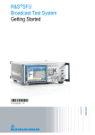
Figure 1: Grid Director 4700 with Standard Fabric Boards – Front
Figure 2: Grid Director 4700 with HyperScale Fabric Boards – Front
11
Introduction
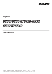
Figure 3: Grid Director 4700 – Rear
12
Mellanox Grid Director 4700 Installation Manual
1.2
Main Features
Ultra-low latency: between 100 and 300 nanoseconds port-to-port
324 QDR (40Gb/s) auto-negotiating QSFP InfiniBand ports in a 19U switch
648 port option can be divided between two racks for weight distribution and greater ease
of cabling
Unique HyperScale™ architecture allows scaling to thousands of nodes with a single tier of
switches (under 400 nanoseconds of latency)
Available bandwidth: up to 51.8 Tbps of non-blocking bandwidth
Simple and fast device management
Fully managed by Mellanox Unified Fabric Manager (UFM)
13
Introduction
Support for longer and more varied cable options
Zero down time with no single point of failure and real-time fault notifications
QSFP ports supporting either copper or optical cables
Redundant, hot-swappable Management Boards, power supplies, and fans meet stringent
availability requirements
InfiniBand specification 1.2 compliant
1.3
Product Architecture
The Mellanox Grid Director 4700 is a modular, rack-mountable chassis for a wide range of
applications. Highlights of the Grid Director 4700 architecture include:
Up to eighteen (18) line boards with 18 QSFP InfiniBand QSFP external interfaces and 18
QSFP InfiniBand links for connectivity between the Line cards and the internal Switch
fabric
Supports up to nine vertical fabric boards
Supports one or two redundant hot swappable Management Boards (sMB) for fabric
management and chassis management; when two Management boards are installed, they
support failover capabilities in the event of failure of one of the boards
Up to 6 power supply units (sPSU-S) with N:1/N:N redundancy
Front-to-rear air cooling system consisting of a horizontal fan unit (sFU-40H)
and a vertical Fan Unit (sFU-40V) for the Grid Director 4700
Cabling for InfiniBand, management, and power located at rear of chassis
Local and remote management and provisioning using CLI (Command Line Interface).
1.3.1
Main Building Blocks
The Grid Director 4700 rear panel has 18 slots in which you can install the Line Boards
(sLB-4018).
14
Mellanox Grid Director 4700 Installation Manual
The following figure is a simplified functional block diagram of the Grid Director 4700
components.
Figure 4: 4700 Block Diagram
The main building blocks of the Grid Director 4700 chassis are listed and described in the
following sections.
Grid Director Midplane
The Grid Director includes a passive Midplane that connects the InfiniBand differential
signals, control signals and power between the different boards in the chassis. (Fabric Board
signals are routed from the front of the chassis to the Midplane; Line Boards are routed from
the rear of the chassis to the Midplane.) The Midplane is not field serviceable.
Line Boards
The rear side of the Grid Director 4700 can host up to up to eighteen 18-Port QDR (40Gbps)
Line Boards (sLB-4018). Each line board has 18 external QSFP interfaces, and 18 internal
4X InfiniBand interfaces for connectivity between the Line cards and the Switch fabric. Line
boards are installed at the rear of the chassis in a horizontal position.
Fabric Boards
The Grid Director 4700 supports up to nine Fabric Boards (sFB) that are installed at the front
of the chassis.
324-port chassis: The sFB-4700 QDR Fabric Board is installed in a standard 324-port chassis,
in a vertical position. Each sFB-4700 has 36 internal QSFP InfiniBand ports.
648-port chassis: The HyperScale Fabric Board is installed in a 648-port chassis in a vertical
position. Each HyperScale Fabric Board has 36 internal QSFP InfiniBand ports and 12
external 12x InfiniBand ports with CXP connectors.
The Fabric Boards determine the total bandwidth of the switching Clos topology within the
chassis.
Grid Director Power Backplane
The power supply unit (sPSU-S) and horizontal fan unit (sFU-40H) modules are connected to
the system through the backplane, which provides the mechanical, control and electrical
interface to the controllable AC/DC 48V power supplies. It allows electric current flow,
15
Introduction
supplies power to the Midplane via a special power harness, and provides connectivity to the
Midplane and the fan units (sFU-40H).
Air Flow Cooling System
The Grid Director 4700 uses front-to-back air flow cooling and provides full internal
redundancy, monitored fans. Fan speed is dynamically controlled as a function of temperature.
The air cooling system includes a horizontal fan unit (sFU-40H), containing eight fans and A
vertical fan unit (sFU-40V) containing five fans.
LED indicators on the horizontal fan unit sFU-40H provide an on-site report on the operating
conditions of the air cooling system modules, and provide an alarm indicator in the event of a
high temperature condition.
InfiniBand Switch Silicon Firmware
Each Line Board and Fabric Board incorporates InfiniBand 36-port switch (ASIC) devices
with locally attached memory containing firmware that controls basic functionality of the
devices. The firmware controls low level link and physical layers functionality and may be
upgraded via Ethernet or RS-232 on the Management Board or in-band via any of the
InfiniBand Line Board ports.
InfiniBand products are RoHS-6 compliant.
Management
The Grid Director 4700 provides a command line interface (CLI) interface for flexible access
the switch comprehensive management capabilities.
Device Management (DM)
Control a device (e.g., a switch) or a device cluster
Remote management, upgrades, logs/alarms
Management Board
The Grid Director supports either one or two hot-swappable Management Boards.
Power Supplies (sPSU-S)
Mellanox Grid Director switches support multiple power supply modules (sPSU-S)
configured in redundant, hot-swap, current sharing mode for N:1 or N:N redundancy,
depending on the configuration, and suitable for 100-240 VAC mains voltage (auto-sense).
The Grid Director supports up to six power supply modules.
1.3.2
Reset Buttons
In the rare event of a 4700 system lock-up, the Reset button can be used to reset the system.
The system has two Reset buttons: one is located on the front panel of the sFU-40H fan
assembly horizontal fan unit, a second one is on the sMB-CM Management Board front panel.
Management Reset
To reset the Grid Director 4700, push any of the reset buttons using a thick wire or tip of a pen.
Pressing the Reset button for one second resets the sMB-CM Management Board only;
pressing the Reset button for at least six seconds resets the entire chassis.
16
Mellanox Grid Director 4700 Installation Manual
1.4
Management
The Grid Director 4700 includes smart device management that provides a simple interface for
deploying, troubleshooting, maintaining and upgrading the switch. With a simple to use CLI
interface, routine tasks such as monitoring the switch operation or upgrading software and
firmware are made simple.
Chapter 2
17
System Configurations
2
System Configurations
2.1
Configuration Summary
This section summarizes the configuration for the Grid Director 4700 modules.
2.1.1
Module Configuration per Chassis
The following table provides a comprehensive list of modules per chassis, as well as the
maximum number of modules that can be installed in a 4700 system.
Some of the components are provided with the basic configuration chassis. The cabling
guide bracket kit (KIT-00022) for HyperScale Fabric Board (chassis with 648 ports) is
optional.
Table 1: Module Configuration per Chassis
2.1.1.1
Module
Name
Description
Number of
Modules per
chassis
Line Board
sLB-4018
Includes 18 QSFP ports
Up to 18
Fabric Board
sFB-4700
Includes 36 internal ports
Up to 9
HyperScale Fabric
Board
sFB-4700-2X
Includes 36 internal and 12 external CXP
(12X) ports
Up to 9
Power Supply
sPSU-S
AC/DC Power supply
Up to 6
Vertical Fan Unit
sFU-40V
Vertical Fan Unit
1
Horizontal Fan Unit
sFU-40H
Horizontal Fan Unit
1
Management Board
sMB-CM
Chassis Management Board
Up to 2
Cable Management
Right
N/A
Right cabling guide brackets for cable
management
1 (right)
Cable Management
Left
N/A
Left cabling guide brackets for cable
management
1 (left)
Optional: cabling guide
bracket kit for
HyperScale Fabric
Board
N/A
Optional: kit for 648 ports (must be
ordered separately). Includes HyperScale
cabling guide bracket and long 19"
brackets
1
Summary of Cabling Management and Rail Kit
Standard chassis configuration (324 ports):
Cable management (standard)
Rail kit
19" bracket attached to the chassis
HyperScale Fabric Board chassis configuration (648 ports):
18
Mellanox Grid Director 4700 Installation Manual
2.1.2
Cable management (standard)
Rail kit
19" bracket attached to the chassis
KIT-00022 includes 3 parts (must be purchased separately for the 648-port
configuration):
1 HyperScale cabling guide bracket
2x bracket long
8 screws
Specifications Summary
The following table summarizes the Grid Director 4700 specifications.
Table 2: Feature Summary Table
Feature
4700
Rack Height
19U
HyperScale Rack Height
20U
Rack Width
19"
Switch Type
Director
Backplane Bandwidth
51.8 Tbps
Line Board Slots
18
Fabric Board Slots
9
Max # of InfiniBand Ports
324 40 Gbps InfiniBand Ports
Optional 648 40 Gbps InfiniBand Ports
Interface Type
QSFP 40 Gbps (QDR) QSFP ports with support for optical
adapters and cables
Redundant Components
Power Supplies (sPSU-S)
Management Boards (sMB-CM)
Embedded Chassis Management (CLI)
2.2
Yes
4700 Configuration and Part Numbers
The following table details the basic configuration of the 4700 chassis.
Table 3: 4700 Basic Configuration
Product Description
Product/Module
Name
P/N
Grid Director 4700 18-Slot QDR Basic Configuration
Grid Director 4700
VLT-30040
sFB-4700 QDR Fabric Board
sFB-4700
VLT-30041
sFB-4700-2X QDR Fabric Board
sFB-4700-2X
VLT-30042
19
System Configurations
Product Description
Product/Module
Name
P/N
sLB-4018 18-Port QDR Line Board
sLB-4018
VLT-30043
sMB-CM Chassis Management Board
sMB-CM
VLT-30044
sPSU-S 1.4KW AC Power Supply Module
sPSU-S
VLT-30046
sFU-40H Horizontal Fan Unit
sFU-40H
VLT-30047-F
sFU-40V Vertical Fan Unit
sFU-40V
VLT-30048-F
The above parts can be ordered separately. The following table provides the list of additional
spare parts and accessories.
Table 4: Spare Parts and Accessories
Description
Comment
P/N
Cable Management Right
Delivered with the
switch
KIT-00023
Set must be ordered per
chassis
KIT-00022
Cable Management Left
Cabling guide bracket kit for HyperScale Fabric Board. It
includes the following parts:
KIT-00024
2 x 19" Long bracket (MEC-00576)
Cable management for Spine in 648 configuration
(MEC-00593)
Screws for assembly (380J30011)
2.3
Switch Internal Topology
High performance computing clusters typically utilize Clos networks, sometimes referred to
as "Fat Tree" or Constant Bisectional Bandwidth (CBB) networks, to construct large node
count non-blocking configurations. A Clos network is a switch topology in which integrated
non-blocking switch chips (crossbars) with a relatively low number of ports are used to build a
non-blocking switch topology supporting a much larger number of endpoints.
The Grid Director 4700 features an internal Clos network with Line Boards as the edge (leaf)
switches and Fabric Boards as the core (spine) switches. Each Line Board switch chip is
connected to each switch chip on the Fabric Boards through one or more InfiniBand
connections.
The path from one external port to another node may require three switch hops:
Hop 1 at a Line Board
Hop 2 at a Fabric Board
Hop 3 at another Line Board.
2.3.1
HyperScale Fabric Boards
HyperScale™ is an interconnect technology, enabling large scale fabrics at reduced latency,
cost and complexity. Mellanox HyperScale fabric cards have double the capacity of standard
fabric cards, as well as external (12x) ports. This combination enables new, modular
configurations that allow scaling to large fabric sizes with the minimum amount of ports and
20
Mellanox Grid Director 4700 Installation Manual
cables wasted for inter-switch connectivity. HyperScale combines the best of Hypercube
(price, simplicity, cabling) and Fat-tree (performance).
HyperScale features:
Each 324 node scalable unit is fully independent (failures, upgrades)
Lowest latency of 400 nanoseconds (vs. 500/750 nanoseconds)
There are fewer cables to wire
Ultimate application performance (large non-blocking islands and minimize application
specific tuning/layout).
2.3.2
Switching Topologies
The following figure illustrates the Grid Director 4700 InfiniBand internal switching
topology.
Figure 5: Grid Director 4700 Switching Topology
21
System Configurations
The following figure illustrates the Grid Director 4700 with HyperScale Fabric Board (spine)
InfiniBand internal switching topology.
Figure 6: Grid Director 4700 HyperScale Spine Switching Topology
The Grid Director 4700 topology feature eighteen symmetrical Line Boards (sLB) and nine
interconnect Fabric Boards (sFB).
Each Line Board (sLB-4018) includes one 36-port 40Gb/s InfiniBand switch chip.
Each Fabric Board (sFB-4700) includes one 36-port 40Gb/s InfiniBand switch chip.
Each HyperScale Fabric Board (sFB-4700-2X) includes two 36-port 40Gb/s InfiniBand
switch chips.
The LEDs on the Fabric Board modules indicate proper connectivity and traffic flow between
each line board and the respective fabric board.
22
Mellanox Grid Director 4700 Installation Manual
2.3.3
HyperScale™ Configurations
HyperScale – Mesh Configuration
Figure 7: HyperScale – Mesh Configuration
Multiple 4700 chassis can be connected in a mesh
This configuration uses 4700 stacking fabric boards and 4700 switches
Ideal for over 648 node counts
CXP-CXP cables are used between switches
HyperScale – Edge Configuration
Figure 8: HyperScale – Edge Configuration
Combines 4700 and 4036 switches
CXP-3QSFP cables are used between switches
Ideal for 324-648 node counts
Chapter 3
23
4700 Specifications
3
4700 Specifications
3.1
4700 Architecture
9 slots of Fabric boards in front of the chassis
18 slots for Line Boards
Based on passive Midplane board which allow the IB differential signals, control signals
and power connectivity between the different boards in the chassis
Cables for InfiniBand, management, and power all located at the rear
Up to 324 InfiniBand QSFP (40 Gbps) ports
Bisectional switch bandwidth (QDR): 51.8 Tbps
3.2
4700 Fabric Board (sFB-4700) Specifications
Up to 9 hot-swappable Fabric Boards running at Quad Data Rate (QDR) which support the
switching Clos topology
Hot-swappable operation with no traffic disruptions
On board high performance, low power CPU for low-level chassis management purposes
EEPROMs to store the switch ASIC ERP (Embedded RISC processor) code
Indicators: Physical connectivity and logical connectivity LEDs per Line Board link port,
power, Rdy and Info LED.
On-board temperature monitoring reported to Management system
Thermal shutdown for over temperature sensing
3.3
4700 Line Board (sLB-4018) Specifications
Up to 18 sLB-4018 hot-swappable Line Boards (sLB) running at 40 Gbps Quad Data Rate
(QDR)
18 auto-sensing QSFP InfiniBand ports (40 Gbps)
Hot-swappable operation with no traffic disruptions
All ports support copper or optical cables
Indicators: Physical connectivity and logical connectivity LEDs per port, power, Rdy and
info LEDs
On board high performance, low power CPU for low-level chassis management purposes
On-board temperature monitoring reported to Management system
Thermal shutdown for over temperature sensing
Data throughput QDR - 2.88 Tbps
24
Mellanox Grid Director 4700 Installation Manual
Port-to-port Latency - Under 100 nanoseconds
Data Virtual Lanes - 8
Management Virtual Lanes - 1
MTU - 4096 Bytes, max
Maximum hops - 1 hop between ports on the same board. 3 hops between different Line
Boards in the same chassis.
3.4
4700 Management Board (sMB-CM) Specifications
Two hot swappable Management Boards, each including on board CPU:
3.5
LEDs
Refer to LED Indicators (on page 31).
Connectors
10/100/1000 Ethernet RJ-45, EIA/TIA-232 Console RJ-45
Reset button
Resets the Management Board or the entire chassis.
Chassis Slot Numbering
Slot numbering at the front of the chassis (for Management Board and Fabric Board) is from
left to right (indication on the horizontal fan unit sFU-40H).
Figure 9: sFU-40H Horizontal Fan Unit
Slot numbering at the rear of the chassis (for Line Boards) is from top to bottom (indication on
the cable guide brackets).
25
4700 Specifications
Figure 10: 4700 Line Board Slot Numbering
For specific instructions, refer to System Cabling (on page 77).
3.6
Torque Settings
Table 5: Torque Settings for Module Assembly
26
Assembly
Torque (in/lb)
sLB-4018 Line Board to chassis
2 (or use manual screwdriver)
sMB Management Board to chassis
2 (or use manual screwdriver)
Rail kit part A to part B
10
Rail to chassis
10
Mellanox Grid Director 4700 Installation Manual
3.7
Assembly
Torque (in/lb)
Fabric Board to chassis
2 (or use manual screwdriver)
Module Configuration Rules
The Grid Director 4700 supports up to two Management Boards. Two Management Boards
are used for redundancy/failover implementation. Use slot one (left) when only one
Management Board is installed. For more information, refer to Installing the Management
Board (sMB-CM).
The Grid Director 4700 supports any Fabric Board configuration (between 1 and 9). When
installing the line boards, start at the bottom of the chassis. For more information, refer to
Installing the Line Board (sLB-4018.
3.8
Clearance Requirements
Table 6: Clearance Requirements
Area
Recommended Minimum Clearance
Front of the rack
36" (90 cm) for technician access and maintenance
Rear side of the rack
24" (60 cm) for human accessibility
Sides of the rack
No limits
Space below the chassis
No limits
Space on top of the chassis
No limits
3.9
Power Data
3.9.1
Type of Power Cord on the Power Supply
Mellanox provides a 15 Amp cord (2 meter jumper), with a universal plug for a power
distribution unit (PDU) for each power supply. The cord is detachable from the Mellanox 4700
chassis/power supply. Cable wiring: 3x14AWG.
3.9.2
Power Requirements
Table 7: 4700 Power Requirements
Power supply modules (sPSU-S) with N:1 or N:N
redundancy.
Up to 6 power supplies
Note: Each power supply has its own power cord.
Electrical rating
100–120/200–240V, 50–60Hz, 60A
12/8A per power feed MAX
Typical power consumption (QDR full configuration)
4000 Watt
Leakage current @254 V [mA]:
>6mA RMS (Note that leakage exceeds 3.5 mA
when more than one power supply is being used)
27
4700 Specifications
Indicators
Operational AC and DC Status LEDs
Operating voltage
100–240 VAC, 50–60 Hz auto-sensing
Power factor
0.98 typical at 230Vac, full load
0.98 typical at 115Vac, full load
Temperature rating
3.9.3
0–45 degrees Centigrade
Power Characteristics
Table 8: Power Characteristics
Attribute
Specification
Comments
Power Entry
54–90 Volts, 47–63 Hz, auto-sensing
Power Rating
1400 Watts @ 220V per module
1200 Watts @ 110V per module
Nameplate Power Rating (VA)
Input: 100V–240Vac @ 16A;
Output: 48Vdc @ 29A
3.9.4
Nameplate Power Rating at 100V
12 A
Nameplate Power Rating at 200V
8A
Power Factor (W/VA)
0.98 typical at 230 Vac, full load; 0.98
typical at 115 Vac, full load
Watts = Volts x Amps x Power
Factor
Power supply efficiency
89% typical at 230Vac, full load rated
power; 85% typical at 115Vac, full
load rated power
A measure of the ability of the
power supply to convert source
AC power into usable DC power
Power Data per Module
Table 9: Power Data by Module
3.9.4.1
Module Name
Module
Watts / Module
Configured
Qty
Total Watts
Fan Tray
sFU-40H
380
1
380
Fan Tray
sFU-40V
250
1
250
Management Board
sMB-CM
45
2
90
18-port Line Board
sLB-4018
110
18
1980
Fabric Board
sFB-4700
110
9
990
HyperScale Fabric Board
sFB-4700-X2
210
9
1890
Calculating the Required Number of sPSU-S Power Supply Modules
To find the minimum number of power supply modules required for a given switch
configuration:
1. Add-up all DC power consumption numbers according to the built configuration.
2. Increase the number of sPSU-S modules according to redundancy requirements. A single
sPSU-S unit provides up 1400 Watts.
28
Mellanox Grid Director 4700 Installation Manual
This formula provides margin for momentary power peaks and enhances reliability by
preventing the power subsystem from continuously operating at maximum power.
3. For redundancy (N:1 or N:N), configure additional power supplies.
Table 10: Module Power Data
Mellanox Grid Director™ 4700
Description
Module Name
DC Power Consumption
[Watt] (*)
Basic chassis configuration
4700
675.0
Single management board
sMB
Horizontal fan units
sFU-40H
Vertical fan unit
sFU-40V
Two power supply units
2 x sPSU-S
sFB, 9-QDR-connections fabric board
sFB
990.0
sMB
sMB-CM
45.0
Modules for the Mellanox Grid Director™ 4700
Description
Module Name
DC Power Consumption [Watt]
sLB-4018, 18 QSFP ports per sLB-4018
sLB-4018
110.0
(*) Add 1.5 Watts for each connected QSFP optical module
Spare Parts for the Mellanox Grid Director™ 4700
3.10
Description
Module Name
DC Power Consumption
[Watt]
sFU-40H, Horizontal Fan Unit
sFU-40H
380.0
sFU-40V, Vertical Fan Unit
sFU-40V
250.0
Calculating Heat Output in BTUs
To compute the approximate BTUs for a given configuration, find the power consumption in
Watts (e.g., from Power Data Per Module; see ), and multiply by 3.408. Example calculations
for specific configurations are shown in the following table.
Table 11: BTUs for QDR Sample Configurations
Configuration
Modules Included
Power (Watts)
Heat Output
(BTUs)
18 ports per sLB-4018
9 sFB-4700, 1 sLB-4018, 1 sFU-40H, 1
sFU-40V, 1 sMB, 2 sPSU-S
2,041W
6,965
108 ports (6 sLBs x 18
port per sLB)
9 sFB-4700, 6 sLB-4018, 1 sFU-40H, 1
sFU-40V, 1 sMB, 2 sPSU-S
2,674W
9,123
29
4700 Specifications
3.11
Configuration
Modules Included
Power (Watts)
Heat Output
(BTUs)
324 ports QSFP copper
9 sFB-4700, 18 sLB-4018, 1 sFU-40H, 1
sFU-40V, 2 sMB, 3 sPSU-S
4,244W
14,479
324 ports QSFP copper +
HyperScale Fabric Boards
9 sFB-4700x2, 18 sLB-4018, 1 sFU-40H, 1
sFU-40V, 2 sMB, 4 sPSU-S
5,279W
18,010
Maximum Heat Dissipation
Table 12: Maximum Heat Dissipation
Maximum heat dissipation
3.12
(max. for full configuration)
22,206 BTU/Hour
Airflow
Table 13: 4700 Airflow
Rated volumetric air flow for a fully configured chassis.
3.13
1300 CFM (Cubic Feet per Minute)
Physical Characteristics
Table 14: 4700 Physical Characteristics
4700 Features
Characteristics
19" rack mountable chassis
19U height
Dimensions
Width - 19" (440 mm)
Depth - 22.75" (578 mm)
Height - 25.6" (650 mm)
Weight
128 to 163 lbs (58 to 74 kg), depending on configuration
Minimum rack depth required for the rail kit
N/A
Maximum rack depth required for the rail kit
N/A
Table 15: HyperScale Physical Characteristics
3.14
HyperScale Features
Characteristics
HyperScale rack mountable chassis
20U height
Weights and Dimensions
Table 16: Weights and Dimensions
Metric (2)
30
English (1)
Unpacked Modules
D (cm)
W (cm)
H (cm)
Kg
Packed Modules
D
W
H
Kg
sMB-CM
33
22
4.5
1.1
40
28
7.5
1.4
D (in)
W (in)
H (in)
Lbs
13
8.7
1.77
2.42
15.7
11
3
3
Mellanox Grid Director 4700 Installation Manual
Metric (2)
sPSU-S
sFU-40H
Chassis
sFU-40V
sFB-4700
sFB-4700x2
sLB-4018
Blank sFB
Blank sLB
Blank sMB
Blank PS
Rail Kit
Cable Mgmnt
Rack Mount Kit for
4700 with HyperScale
Fabric Boards
English (1)
36
13
4.5
1.85
14
5
1.8
4
42
21
12
2.6
16.5
8.2
4.7
5.7
33
43
12
3.9
13
17
4.7
8.6
44
52
19
4.5
17.3
40.4
7.4
9.9
68
44
84
81
26.77
17.32
33
178.57
88
57
119
110
34.6
22.4
46.85
242.5
38
67
14
4.8
15
26.3
5.5
10.6
46
73
22.5
6.2
18
28.7
8.85
17.7
66
32
4
3.2
30
12.6
1.57
7
78
40
7
3.9
28.7
16
3.54
8.6
66
32
4
4.5
30
12.6
1.57
11.2
78
40
7
5.4
30.7
15.75
2.75
11.9
43
33
4
2.9
17
13
1.57
6.4
51.5
40
9.5
3.5
20.2
15.7
3.74
7.7
66
32
4
1.9
30
12.6
1.57
4.2
78
40
7
2.6
30.7
15.75
2.75
5.7
43
3
4
0.26
17
1.18
1.57
0.57
63
8
3.5
0.36
24.8
3.14
1.38
0.8
4
22
4
0.12
1.57
8.66
1.57
0.26
63
8
3.5
0.22
24.8
3.14
1.38
0.48
4
15
5
0.09
1.57
6
2
0.12
63
8
3.5
0.19
24.8
3.14
1.38
0.42
53.2
14.5
4.3
9
21
5.7
1.7
19.84
62
14
7.5
8
24.5
5.5
2.95
17.63
64
13
4
2.8
25
5
1.57
6.17
75
23
15
3.7
29.5
9
6
8.15
-
-
-
-
41.5
75
12.5
12.2
-
-
16.34
-
29.5
-
4.92
27.12
(1) 1 in = 2.54 cm (2) 1 kg = 2.205 lbs
3.15
LED Indicators
This section specifies the LED indicators of the different Grid Director 4700 modules.
31
4700 Specifications
3.15.1
sLB-4018 Line Board LEDs
Table 17: sLB-4018 Line Board LEDs
Indication
LED Description
Remarks
Link State
The two LEDs in each pair are as follows:
18 Amber LEDs
Green – ON indicates physical link up
Indicates the state of the
QSFP connectivity.
18 Green LEDs
Amber – ON indicates logical link up
HW only
The LED states are as follows:
OFF – no link detected
ON – the port has a link
Blinking:
Green – indicates errors
Amber – indicates data activity
Power (Green)
HW only
ON – indicates that all board voltage levels are
operating normally
OFF – indicates a problem in power supply to the board
Info (Blue)
General purpose LED for management use
User only
OFF – No attention required
Blinking – Chassis attention required
Card Ready (Green)
OFF – Card not Ready
ON – Card ready
Blinking Slowly – Card loading
Blinking Fast – Card problem
3.15.2
Fabric Board (sFB-4700) LEDs
Table 18: Fabric Board (sFB-4700) LEDs
Indication
LED Description
Remarks
Link
18 Amber LEDs
Each pair of LEDs indicates the state of ports of each
Line Board.
18 Green LEDs
The two LEDs in each pair are as follows:
HW only
Green – ON indicates physical link up
18 pairs of internal link
indication LEDs. Each
pair of LEDs indicates
the state of two ports of
each Line Board.
Amber – ON indicates logical link up
The LED states are as follows:
OFF – no link detected
ON – link detected
Blinking:
Green – indicates errors
Amber – indicates data
Power (Green)
HW only
ON – indicates that all board voltage levels are operating
normally
OFF – indicates a problem in power supply to the board
Info (Blue)
32
General purpose LED for management use
Mellanox Grid Director 4700 Installation Manual
Indication
LED Description
User only
OFF – No attention required
Remarks
Blinking – Chassis attention required
Card Ready (Green)
OFF – Card not Ready
ON – Card ready
Blinking Slowly – Card loading
Blinking Fast – Card problem
3.15.3
HyperScale Fabric Board (sFB-4700-2X) LEDs
Table 19: HyperScale Fabric Board (sFB-4700-2X) LEDs
Indication
LED Description
Remarks
Link
18 Green LEDs
Each LED indicates the state of ports of each Line
Board.
HW only
ON – indicates physical link up
18 pairs of internal link
indication LEDs. Each LED
indicates the state of two ports
of each Line Board.
OFF – no link detected
Blinking – indicates errors
CXP Link
The two LEDs in each pair are as follows:
36 Amber LEDs
Green – ON indicates physical link up
36 Green LEDs
Amber – ON indicates logical link up
HW only
The LED states are as follows:
Indicates the state of the 36
external QSFP port
connectivity.
OFF – no link detected
ON – the port has a link
Blinking:
Green – indicates errors
Amber – indicates data activity
Power (Green)
HW only
ON – indicates that all board voltage levels are
operating normally
OFF – indicates a problem in power supply to the
board
Info (Blue)
General purpose LED for management use
User only
OFF – No attention required
Blinking – Chassis attention required
Card Ready
(Green)
OFF – Card not Ready
ON – Card ready
Blinking Slowly – Card loading
Blinking Fast –Card problem
3.15.4
Management Board (sMB-CM) LEDs
Table 20: Management Board (sMB-CM) LEDs
Indication
LED Description
Remarks
Fans (Green)
OFF – All fan drawers are OK.
Two fan drawers
33
4700 Specifications
Indication
LED Description
Remarks
ON – Vertical and Horizontal fan unit fault indication.
Indicates that at least one of the 13 fans has failed.
Temp (Orange)
OFF – Indicates normal temperature levels.
Temp (Orange)
ON – Indicates an over-temperature fault on the chassis.
FM Active (Green)
OFF - Fabric Manager is not active
ON - Fabric Manager running on the Management
Board
Blink - Fabric Manager is standby on the Management
Board
DM Active (Green)
OFF - Device Manager is not active
ON - Device Manager running on the Management
Board
Power (Green)
OFF – indicates a problem in power supply to the board
HW Only
ON – indicates that all board voltage levels are
operating normally
Info (Blue)
General purpose LED for management use
User only
OFF – No attention required
Blinking – Chassis attention required
PSU OK (Green)
OFF – N/A
ON – System Power OK
Blinking – System Power problem
Eth—1 and 2
3.15.5
Two LEDs: Link (Green) and Activity (Orange)
AC-DC power supply fault
indication. Indicates that at
least one of the main AC-DC
power supplies has an AC or
DC fault
Eth—1 and 2
sFU-40H Horizontal Fan Unit LEDs
Table 21: sFU-40H Horizontal Fan Unit LEDs
Indication
LED Description
Temp (Orange)
ON – Indicates an over-temperature fault on the
chassis.
OFF – Indicates normal temperature levels.
sFU-40V (Orange)
ON – Vertical fan unit fault indication. Indicates that
at least one of the five fans in the vertical fan unit has
failed.
OFF – All fans in the vertical fan unit are OK.
sFU-40H (Orange)
ON – Horizontal fan unit fault indication. Indicates
that at least one of the eight fans in the horizontal fan
unit has failed.
OFF – All fans in the horizontal fan unit are OK.
PS (Orange)
AC-DC power supply fault indication.
ON – Indicates that at least one of the main AC-DC
power supplies has an AC or DC fault.
OFF – All PSUs are OK.
34
Remarks
Mellanox Grid Director 4700 Installation Manual
3.15.6
sPSU-S Power Supply LEDs
Table 22: sPSU-S Power Supply LEDs
3.16
Indication
Description
DC ON (Green)
ON – Indicates that the DC power source is present.
AC ON (Green)
ON – Indicates that the AC power source is present.
Environmental Specifications
Table 23: 4700 Environmental Specifications
3.17
Ambient Operating Temperature
32° to 113°F (0° to 45°C)
Operating Humidity
15 to 80%, non-condensing
Operating Altitude
0 to 9843 ft (3000m)
Storage Temperature
-13° to 158°F (-25° to +70°C)
Storage Humidity
5 to 90% non-condensing
Storage Altitude
0 to 15,000 ft (4570m)
Acoustic Data
Acoustic noise is reported in accordance with ISO 7779 [ECMA 74] standard.
3.18
Reliability (MTBF)
The Mean Time between Failures (MTBF) for individual switch components is shown in the
following tables. These figures indicate the mean elapsed time until a single component fails
in the module, whether or not that failure impacts the operation of the switch. Note that in
many cases redundant modules can be configured, which dramatically increases the overall
system Mean Time between Critical Failures (MTBCF).
MTBF per 4700 model types:
Model A: The system configuration is a fully populated chassis with 18 line cards, 9 fabric
cards, 3 power supplies, 1 Management Board and 2 fan modules (Horizontal and Vertical
drawers).
Model B: The system configuration is a fully populated chassis with 18 line cards, 9 double
fabric cards, 4 power supplies, 1 Management Board and 2 fan modules (Horizontal and
Vertical drawers).
Table 24: Reliability (MTBF) Specifications
4700 QDR Director
FPMH
MTBF (Hours)
Model A
66.308
15,081
Model B
75.431
13,257
35
4700 Specifications
Table 25: MTBF per Module Data
3.19
Chassis/Module
Description
sFB-4700
9 QDR port connections fabric board
519, 426
sFB-4700-2X
9 QDR port connections x2 fabric board
345,941
sLB-4018
sLB-4018, 18 QSFP ports per sLB-4018
419,866
sMB-CM Management
Board
Management board
441,273
sFU-40H Horizontal Fan
Unit FRU
Horizontal fan unit
708,754
sFU-40V Vertical Fan Unit
FRU
Vertical fan unit
913,145
sPSU-S
Power supply
2,303,086
Certifications
cMETus UL 60950-1:07 Second Ed.
CSA C22.2 No. 60950-1-07 Second Ed
cTUVus UL60950-1: 07 Second Ed.
S-Mark Argentina
CB Certificate and report, according to IEC 60950-1 Second Ed.
KCC Korea
Gost-R
CE according to EN 60950-1:06 Second Ed
S-Mark
EMC Certifications
FCC Part 15, Subpart B, Class A and testing to ANSI 63.4
Industry Canada
ICES-003 (CAN/CSA-CEI/IEC CISPR 22:02)
CE EN55022: 1998 + A1:2000 + A2:2003
EN55024: 1998 + A1:2001 + A2:2003
36
EN 61000-3-2:00+A2(05) Harmonic current emissions
EN 61000-4-2: 1995 + A1: 98 + A2: 2001
EN 61000-4-3: 02 + A1: 2002
EN 61000-4-4: 1995 + A1: 01 +A2:2001
EN 61000-4-5: 1995 + A1: 2001
EN 61000-4-6: 1996 + A1: 2001
EN 61000-4-8: 1993 + A1:2000
EN 61000-4-11: 1994 + A1: 2001
MTBF (Hours)
Mellanox Grid Director 4700 Installation Manual
EN 61000-3-3:95+A1 (01) Voltage fluctuations and flicker
Japan VCCI Technical Requirements, V.3/2001.04/CISPR 22:1997 + A1: 2000 + A2:
2002, Class A.
Australian/New Zealand C-Tick, AS/NZS CISPR 22:04
KCC Korea
Restricted Hazardous Substances Certification
RoHS-6
InfiniBand Certification
IBTA 1.2
3.20
Declarations
3.20.1
Declaration of Conformity
Mellanox products comply with the Radio & Telecommunications Terminal Equipment
Directive 99/5/EEC, the EMC Directive 2004/108/EC, and of the Low Voltage Directive
2006/95/EC.
3.20.2
Hazardous Substances (RoHS 6) Compliance Declaration
Mellanox products comply with the RoHS directive.
37
4700 Specifications
3.21
Label(s)
The Grid Director 4700 label (example) below shows safety and EMC text and logos.
Figure 11: 4700 Label (example)
3.22
Gost-R Certification
Mellanox products comply with the Gost-R Russian safety regulations.
3.23
KCC-Korea Certification
Mellanox products comply with the Korean KCC regulations.
3.24
Oscillator Speeds
Oscillator speeds are shown in the following table.
Table 26: Oscillator Speeds
38
Mellanox PN
Description
Frequency
Card
141C00005
CRYSTAL PECL156.25MHZ,
JOE75-SMD, H=1.4MM
156.25 MHz
sFB-4700, sFB-4700-2X,
sLB-4018
OSC-00005
OSCILLATOR PECL 100MHZ 7 X 5
X 1.9MM +50PPM
100MHz
sFB-4700, sFB-4700-2X,
sLB-4018, sMB-CM
141C71200
OSCILLATOR 125MHZ 5.0 X 7.0 X
2.0 MM
125MHz
sFB-4700, sFB-4700-2X,
sLB-4018, sMB-CM
Mellanox Grid Director 4700 Installation Manual
3.25
Mellanox PN
Description
Frequency
Card
OSC-00009
OSCILLATOR, 2.5V HCMOS/TTL
66.66MHZ 50 PPM
66.66MHz
sFB-4700, sFB-4700-2X,
sLB-4018, sMB-CM
141C65000
OSCILLATOR 50MHZ 7.5 X 5.0 X
1.4 MM 3.3V +50PPM
50MHz
sFB-4700, sFB-4700-2X,
sLB-4018
OSC-00008
OSCILLATOR 3.3V CMOS 48MHZ
50 PPM
48MHz
sMB-CM
OSC-00007
OSCILLATOR HCMOS/TTL
25MHZ
25MHz
sMB-CM
OSC-00011
OSCILLATOR HCMOS/TTL
25MHZ 2.5V
25MHz
sFB-4700, sFB-4700-2X,
sLB-4018
OSC-00010
OSC. HCMOS/TTL 25MHZ 1.8V
50PPM TR=4NS MAX 7X5MM
25MHz
sMB-CM
OSC-00006
OSCILLATOR SE 1.8V 19.2MHZ
+-50PPM
19.2MHz
sMB-CM
Shock and Vibration Test Reports
Prepare the Grid Director 4700 to ship in a rack by carefully following the rail kit installation
instructions, as detailed in Assembling and Mounting the Rails. The Grid Director 4700 is
susceptible to shock and vibration if the rail kit installation instructions are not followed
precisely.
The following tables detail the shock and vibration test reports, compliant with shipping in a
rack.
3.25.1
4700 Test for Transportation without a Rack
Table 27: Vibration
Test
Description
Vibration Axes
3 axes (X,Y,Z)
Non-Operating Random
Vibration
Frequency range:
5–300Hz
Vibration level:
Z axis, 1.03g RMS
X,Y axis 0.698g RMS
Operating Sine
Vibration
Operating Shock
(half-sine)
Vibration test for each axis
60 minutes
Frequency range:
5-500Hz
Vibration level:
0.1G peak
Vibration test for each axis
40 minutes
Vibration Level
Z axis, 5g peak
Shock test for Z axis
3 shocks, 10ms duration each shock
39
4700 Specifications
Table 28: Free Fall
3.26
Test
Description
Drop Height
0.1 meter
Number of drops of test
item
One drop performed on the bottom face, 2 edges and 2 corners of the test item
Total number of drops
5 drops
Export Information
Composite Theoretical Performance (CTP) is a calculation measured in MTOPS (millions of
theoretical operations per second).
The 460EX/460GT contain a 440H6 core (not a 460 core; it is called 460 to distinguish it as a
90 nm core).
The CTP (in MTOPS) for the PPC440 core = (17/18) * F (where F is the CPU clock rate in
MHz).
Refer to the following table accordingly:
Table 29: Export Information
3.27
CTP value for the PPC440 core 460EX/460GT @
600MHz
~ 567 MTOPS
CTP value for the PPC440 core 460EX/460GT @
1000MHz
~ 944 MTOPS
ECCN
5A991C
Shipping Restrictions
None.
40
Mellanox Grid Director 4700 Installation Manual
3.28
Center of Gravity Data
This section provides the Grid Director 4700 center of gravity specifications. The
measurement origin starts at the front lower left corner of the chassis.
Figure 12: Center of Gravity Data
Center of gravity for minimum, typical, and maximum configurations are shown in the
following table.
Table 30: Center of Gravity Data
3.29
4700
Width (X) - mm
Depth (Y) - mm
Height (Z) - mm
Empty Chassis
220
250
345
Basic Configuration
220
270
330
Full Configuration
220
300
320
Statement of Volatility
Refer to the Grid Director 4700 Statement Of Volatility document.
Chapter 4
41
Packing and Unpacking
4
Packing and Unpacking
This chapter provides step-by-step instructions for packing and unpacking the Grid Director
4700 chassis.
4.1
Package Contents
The Grid Director 4700 is supplied in a heavy duty tri-wall cardboard box secured with
packing straps.
For information about the various 4700 configurations and items shipped with the chassis,
refer to Chapter 1 (on page 18).
The basic 4700 shipping contents are as follows:
Grid Director 4700
Horizontal fan unit (sFU-40H)
Vertical fan unit (sFU-40V)
Management board (sMB-CM)
Two power supply units (sPSU-S).
The Grid Director 4700 chassis is shipped with a horizontal fan unit (sFU-40H) and a vertical
fan unit (sFU-40V) installed at the front of the chassis and two power supplies at the rear of the
chassis.
Additional components include:
Rail kit for rack installation
Cabling guide brackets
One power cord per power supply
One console cable
A grounding kit
Mellanox Getting Started Short Guide
Two product CDs (one containing the software, one containing the documentation).
Verify that the package contains the items detailed in the packing list before you begin to
install the Grid Director 4700.
Check for loose parts or any visible damage to the contents. If any damaged or missing parts
are detected, notify your local Mellanox representative.
42
Mellanox Grid Director 4700 Installation Manual
Part Number
Description
1
Grid Director 4700
2
Top Foam
3
Cable Management
4
Mounting Rails (Left and Right)
5
Foam Plate
6
Carton Plate – placed at the top of the rear of the chassis to protect the opening
7
Bottom Foam
43
Packing and Unpacking
Part Number
4.2
Description
8
Cardboard Box
9
Pallet
Unpacking the Grid Director 4700
To unpack the Grid Director 4700 chassis:
1. Carefully cut the packing straps and open the carton box.
2. Remove the box from around the chassis by sliding it upwards, as shown.
The Grid Director 4700 chassis in its partially unpacked state is shown as follows.
The upper packing foam covering the Grid Director 4700 contains the following
components:
44
Rail kit
Cabling guide brackets (cable management)
Mellanox Grid Director 4700 Installation Manual
Screw kit
Grounding kit
Console cable
Power cables
Getting Started Short Guide – Mellanox Solution
CD with documentation and software utilities fastened on top of the Grid Director 4700
chassis wrapped in an antistatic bag.
3. Remove all of the accessories listed above and as well as the packing foam on top of the
chassis.
4. Lift the Grid Director 4700 from the pallet and place it on a flat surface. Due to the weight
of the Grid Director 4700 chassis, two people are required to perform this.
Use the four handles at top of chassis to carry or move the unit.
Use safe lifting procedures when moving the unit to avoid personal injury.
4.3
Packing the Grid Director 4700 Switch
If you need to move the Grid Director 4700 switch to a different physical location, pack the
equipment according to the following procedure.
To pack the Grid Director 4700 chassis:
1. Insert the foam grip on the pallet.
2. Position the chassis on the foam. Verify that the two sFU-40H horizontal fan unit handles at
front of chassis point to the two niches in the bottom foam.
3. Place the foam plate then the top foam on top of the chassis. The foam protection padding
fits snugly over the chassis top.
4. Insert the accessories in the top foam dedicated locations.
5. Slide the cardboard box over the chassis and foam with the flaps facing up. Make sure it sits
well on the pallet indent
6. Fasten the box and secure it with the pallet using packing straps.
The packing list and part numbers (bar codes) are glued to the box. Safety labels are
printed on the box.
45
Packing and Unpacking
Figure 13: 4700 Switch Packed
Chapter 5
46
Mellanox Grid Director 4700 Installation Manual
5
Preparing for Installation
This chapter describes how to prepare your site.
Read this chapter before you install the switch.
5.1
Tools Required for Installation
The following tools and materials are required for mounting the Grid Director 4700 chassis.
Table 31: Required Tools and Materials
Quantity
Description
1
Phillips screwdriver
1
Utility knife
1
Measuring tape
1
Crimping tool
1
Wire stripping tool
1
Digital Voltmeter (DVM)
Floating nuts
Phillips screws
5.2
Site Planning
It is essential that you plan the proper location and layout of your equipment rack. Equipment
placed too close together or in an inadequately ventilated area can cause an increase in
temperature and inadequate cooling conditions. In addition, be sure to place the system
panels so that they are accessible and easy to reach system panels inaccessible and difficult to
maintain.
Plan your site configuration and prepare your site before installation to ensure normal
operation and avoid unnecessary maintenance.
Refer to Environmental Specifications for the operational and non-operational environmental
site requirements for the Grid Director 4700. The system can continue to operate within
specified environmental ranges; however, a measurement that approaches the minimum or
maximum of a range indicates a potential problem.
You can maintain normal operation by anticipating and correcting environmental conditions
before they exceed the maximum operating range. Verify the site power for the type of device
you are installing. Power requirements are useful for planning the power distribution system
needed to support the Grid Director 4700. Heat dissipation is an important consideration for
sizing the air-conditioning requirements for an installation.
47
Preparing for Installation
Refer to Power Data and Calculating Heat Output in BTUs for 4700 power and heat ratings.
To prevent a loss of input power, verify that the total maximum load on the circuit
supplying power to the power supply is within the current ratings of the wiring and
breakers.
5.3
Rack Requirements
The 19U-high 4700 chassis is mounted in a standard 19" rack with the fabric boards facing the
front of rack and the Line Board InfiniBand ports and sMB-CM facing the rear of the rack.
The rack should support the mechanical and environmental characteristics of a fully populated
4700 chassis as listed in Environmental Specifications.
The rack mounting holes conform to the IEA-310 standard for 19-inch racks. Precautions
should also be taken to guarantee proper ventilation and ambient temperature is maintained for
air intake at the front of the chassis and exhaust in the rack.
The HyperScale cable guide requires an additional 1U of rack space, making the total
height 20U instead of 19U.
5.4
Clearance Requirements
You should be certain to provide sufficient clearance around the racks to install and maintain
the Grid Director 4700. Clearance specifications are detailed in Chapter 3 (on page 27).
5.5
Site Environment Specifications
The system can continue to operate within specified environmental ranges; however, a
measurement that approaches the minimum or maximum of a range indicates a potential
problem. You can maintain normal operation by anticipating and correcting environmental
conditions before they exceed the maximum operating range.
Refer to Environmental Specifications (on page 35) for operating and non-operating
environmental site requirements.
5.6
Chassis Grounding
Grounding connection is performed at the customer's site. Connect the chassis to a
reliable earth ground. Ensure that the host is connected to earth ground during normal use.
The ground wire should always be hooked up first and disconnected last.
Never defeat the ground conductor or operate the equipment in the absence of a suitably
installed ground conductor. Contact the appropriate electrical inspection authority or an
electrician if you are uncertain that suitable grounding is available.
48
Mellanox Grid Director 4700 Installation Manual
The Grid Director 4700 is delivered with a grounding stud kit. The system must be
permanently grounded using the grounding stud.
The grounding kit includes the following items:
A 10-32 5/8" screw
3 spring washers
2 nuts #10
Ground label
Safety warning label.
This grounding procedure requires a 6 AWG Grounding Cable.
Figure 14: 4700 Grounding Connection
Figure 15: Ground Warning Label
49
Preparing for Installation
The Grid Director 4700 provides two grounding options, as shown. For convenience,
grounding can be performed from any of these locations.
Figure 16: Grounding Holes for 4700
Install the grounding stud before you mount the Grid Director 4700 chassis onto the rack.
50
Mellanox Grid Director 4700 Installation Manual
To install the Grounding Stud:
1. Insert a 10-32 5/8" screw through the Grounding hole, rear-to-front, as shown.
2. Add a spring washer onto the 10-32 5/8" thread, this time front-to rear.
3. Add a nut #10.
4. Add another spring washer.
5. Insert the 6 AWG grounding cable. Connect the other end of the grounding cable to a
grounding point at your site.
6. Add another spring washer. Make sure that the grounding cable is tightly secured between
the two spring washers.
7. Secure everything with a grounding nut #10.
8. Apply the Ground label under the grounding nut.
9. Apply the Safety Warning label on the side of the chassis, near the grounding stud.
51
Preparing for Installation
5.7
Power Requirements
Power requirements are useful for planning the power distribution system needed to support
the Grid Director 4700. Heat dissipation is an important consideration for sizing the
air-conditioning requirements for an installation. Verify the available power source at the site
for the type of device you are installing.
Refer to Power Data (on page 27) for power specifications and heat ratings.
To prevent a loss of input power, verify that the total maximum load on the circuit
supplying power to the power supply is within the current ratings of the wiring and
breakers.
The Grid Director 4700 requires multiple power connections using standard 3-wire AC power
cords including a safety ground. The input voltage is auto adjusting for 100/240 VAC, 50Hz or
60Hz power connection. If you do not use the power cords supplied by Mellanox, the power
cords should be rated for 15A or higher.
The Grid Director 4700 includes hot-swappable power supply units (sPSU-S) with N:1 or N:N
redundancy. A non-redundant power configuration includes the minimum number of power
supplies required by the system for operation.
N:N redundancy implies that each non-redundant power supply is fully backed up by a
redundant power supply, which is routed to a different power source. This provides for full
power backup in case the first power source is disconnected.
N:1 implies that all the system non redundant power supplies are connected to a single power
source and are backed up by one spare power supply.
N:M is for spare power supplies. N stands for required units, while M stands for spares. This
covers 2:1, as well as 3:2 redundancies.
The Grid Director 4700 supports up to six load sharing 1400W power supplies with separate
AC power connections. Each power supply must be powered from separate sockets with
circuit breaker 16A for Europe or 20A for North America.
The amount of required power supplies per system is set according to system configuration.
When the Grid Director 4700 is fully configured, it supports N:1 redundancy, as shown in the
example below.
52
Mellanox Grid Director 4700 Installation Manual
Figure 17: 4700 Fully Configured - N:1 Redundancy
The following table describes the Grid Director 4700 N:1, N:N, and N:M redundancies.
Table 32: 4700 QDR N:1/N:N Redundancy
Configuration
Modules Included
Non-redundant
power supplies
N:1
N:N or N:M
18 ports QSFP
copper
9 sFB-4700
2
3 (2:1)
4 (2:2)
2
3 (2:1)
4 (2:2)
3
4 (3:1)
6 (3:3)
1 sLB-4018
1 sFU-40H
1 sFU-40V
1 sMB-CM
2 sPSU-S
162 ports QSFP
copper
9 sFB-4700
9 sLB-4018
1 sFU-40H
1 sFU-40V
1 sMB-CM
2 sPSU-S
324 ports QSFP
copper
9 sFB-4700
18 sLB-4018
1 sFU-40H
1 sFU-40V
2 sMB-CM
3 sPSU-S
Chapter 6
53
Rack-Mounting the 4700 Chassis
6
Rack-Mounting the 4700 Chassis
6.1
Mounting Process Summary
The 4700 chassis is mounted in a standard 19" rack with the Fabric Boards facing the front of
the rack. The 4700 is provided with an adjustable rail kit to accommodate racks of differing
depth. The 4700 rail kit is adjustable to accommodate a distance of depths of 24" (60 cm) to
40" (100 cm) between the rack’s EIA rails.
In addition, the chassis is delivered with cable management (cabling guide brackets).
The HyperScale cable guide requires an additional 1U of rack space, making the total
height 20U instead of 19U.
The mounting process consists of the following stages:
1. Standard chassis installation (up to 324 port configuration)
Assembling and mounting the rail.
Mounting the chassis on the rail, in a rack.
Installing the cable management.
2. HyperScale chassis installation (up to 648 port configuration)
Assembling and mounting the rail.
Remove the standard 19" brackets (keep the screws for installation of the 19" brackets).
Install the 19" long brackets (part of P/N KIT-000222).
Slide and mount the chassis into the rack.
Installing the cable management.
Install the HyperScale cabling guide bracket. Note that you should count 5 slots to the
left of the bracket prior to installing it.
Refer to Chapter 9 (on page 77) for more information.
Because of the 4700 chassis weight, at least two people are required to mount this unit in
a rack.
6.2
Assembling and Mounting the Rails
This section describes how to assemble and mount the rails:
Rail kit and mounting components
Overview of the assembling and mounting procedure
Assembling and mounting procedure in detail, the steps accompanied by figures, showing
the components as they appear aligned and then assembled one by one.
54
Mellanox Grid Director 4700 Installation Manual
6.2.1
Rail Kit and Mounting Components
The 4700 package includes:
Rail kit
Mounting ears (or 19" brackets) that are factory installed at the front of the chassis
The supplied rail kit is adjustable to allow for mounting the chassis in racks of varying depths.
The rail bracket kit includes the following items:
Left bracket (left rail)
Right bracket (right rail)
2 inserts (with elongated holes) – same for both left and right rails
8-32 screws 5/8" (qty: 2 x 8)
8-32 screws 3/8" (qty: 2 x 3) – to be used in case of chassis transportation in a rack.
8-32 nuts (qty: 2 x 11)
M4 flat washers (qty: 2 x 11)
Spring washers (qty: 2 x 8)
Tooth washers (qty: 2 x 3)
Clip nuts are not provided.
6.2.2
Rail Kit Assembly Overview
This section shows a diagram of an assembled rail kit and provides the procedures for
assembling the rail kit.
55
Rack-Mounting the 4700 Chassis
The following image shows the two rails completely assembled and displays the left rack
assembled to the rack, and how the left rail looks when it is attached to the rack.
Figure 18: Overview of Assembled Rail Kit
Use all 8 screws. Note the order of the nuts and washers.
Select the inner openings or outer openings (as shown), depending on the rack vertical rails
locations. Inside ledges are used for sliding the chassis along the rail.
Procedure Summary
Perform each step of the following procedure for both rails.
1. Use 8-32 5/8" screws and flat washers and spring provided with the kit to assemble the rail,
positioning the insert in front of the bracket.
2. For each of left and right rails, take a bracket and attach an insert (the two inserts are
identical). At this stage, position the two parts to fit the distance between the rack rails of
each side.
Make sure that you are using the right bracket for the right rail (right side when facing
the front of the rack) and the left bracket for the left rail (left side when facing the front
of the rack). The insert is identical for both rails.
The rail supports six or eight 8-32 5/8" screws. Eight is recommended.
3. Select the counter sunk holes in the bracket.
4. Assemble the rail with flat washers, spring washers, and nuts.
IMPORTANT: Do not tighten the screws at this time.
5. Align the rail mounting holes with the mounting holes in the equipment rack.
6. Install the rail kit by positioning the rail brackets in alignment with the adequate mark on
the rack.
56
Mellanox Grid Director 4700 Installation Manual
7. Attach the front side of the rail to the rack’s front vertical side rail with 2 screws for each
side and the rear side of the rail to the rack’s rear vertical side rail with 2 screws for each
side.
IMPORTANT: If you do not tighten the screws, the chassis cannot be mounted safely in
the rack.
8. Repeat steps 1 to 3 to assemble the other rail and mount it on the other side of the chassis;
the rails are now ready for chassis installation.
IMPORTANT: When mounting the rail ensure box-to-box vertical alignment on all four
rack rails. See that the bottom side of the rail is aligned with the 1U marking on the rack
rail.
6.2.3
Rail Kit Assembly Procedure
This section presents the procedure for assembling and mounting the rail kit. Each step is
accompanied by a figure, showing the components as they appear aligned and then assembled
one by one.
In addition, eight screw sets are included, comprising one screw, one nut, and two washers.
To assemble the rail:
1. Use 8-32 5/8" screws and flat washers and spring provided with the kit to assemble the rail,
positioning the insert in front of the bracket as shown below.
1. For each of left and right, take a bracket and attach an insert (the two inserts are
identical). At this stage, position the two parts to fit the distance between the rack rails
of each side.
Make sure that you are using the right bracket for the right rail (right side when
facing the front of the rack) and the left bracket for the left rail (left side when facing
the front of the rack). The insert is identical for both rails.
57
Rack-Mounting the 4700 Chassis
The rail supports six or eight 8-32 5/8" screws. Eight is recommended.
Figure 19: Positioning the Insert in Front of the Right Bracket
Figure 20: Assembling the Rail Bracket
2. Select the round holes in the bracket.
3. Assemble the rail with flat washers, spring washers, and nuts.
4. Do not tighten the screws at this time.
Figure 21: Right Rail Assembly (top) and Left Rail Assembly (bottom)
58
Mellanox Grid Director 4700 Installation Manual
2. Align the rail mounting holes with the mounting holes in the equipment rack as displayed
previously.
1. Position the rail brackets in alignment with the 1U mark on the Rack. Note: you can
install any equipment adjacent to the rail kit as long as you align the rail kit with the "U"
mark.
Figure 22: U Alignment
2. Attach the front side of the rail to the rack’s front vertical side rail with
2 screws and the rear side of the rail to the rack’s rear vertical side rail
with 2 screws.
The following figure shows the left rail completely assembled and what it looks like when
it is attached to the rack.
59
Rack-Mounting the 4700 Chassis
3. Go back and tighten the screws that were used to connect the two parts of the rail in Step 1.
IMPORTANT: If you do not tighten the screws, the chassis cannot be mounted safely in
the rack.
4. Repeat steps 1 to 3 to assemble the other rail and mount it on the other side of the chassis;
the rails are now ready for chassis installation.
IMPORTANT: Ensure box-to-box vertical alignment in all four connections. See that the
bottom side of the rail is aligned with the 1U marking on the rack rail.
6.3
Mounting the 4700 in a Rack (Standard Installation)
This section provides instructions on how to mount the 4700 in a rack.
Screws and clip nuts to connect the chassis to the rack and rail kit to rack are not supplied
by Mellanox.
Make sure that the grounding stud is installed before performing the steps below (see
Chassis Grounding (on page 48)).
Prerequisites:
Rail kit
19" bracket attached to the chassis
To install the 4700 chassis:
1. Lift the chassis using a hydraulic chassis lift (or another adequate tool) and place it on the
rails, with front of the chassis towards you, as shown in the figure below.
2. Slide the chassis into place. Note: At least two people are required to perform this
operation.
3. Secure the chassis onto the rack by aligning the holes in the front of the chassis with the
mounting holes in the equipment rack’s vertical front rail.
60
Mellanox Grid Director 4700 Installation Manual
4. Secure the chassis through the holes in the Front Rack rail using 16 screws (8 for each side)
and adequate clip nuts, as shown.
5. To stabilize the chassis for transport, secure the 4700 chassis onto the rail by using three
8-32 screws, 3/8" tooth washers, and flat washers, insert them into the oval holes and the
threaded holes in the chassis side walls (see Figure 6-10).
61
Rack-Mounting the 4700 Chassis
Once the rack is installed on the premises, these screws should be taken away so that you
can remove the chassis in case the sides of the rack are not accessible.
Figure 23: Securing the 4700 Chassis for Transport - Regular Configuration
Figure 24: Securing the 4700 Chassis for Transport - HyperScale Configuration
6.4
Mounting the HyperScale Chassis in a Rack
The installation kit includes:
Rack mount bracket for recessed installation supporting cabling from both sides
HyperScale cabling guide bracket [for CXP cables]
Screws (you will need to save the screws from the original brackets + use screws from the
kit)
62
Mellanox Grid Director 4700 Installation Manual
To mount the HyperScale 4700 chassis into the rack:
1. Install the rail kit, as described in Assembling and Mounting the Rails (on page 54).
2. Swap the standard 19-in rack mount bracket with the 19-in long bracket (provided in the
kit) using the screws from the unmounted the 19-in bracket and screws from the kit (see
Figure 6-10)
If the chassis is installed, disassemble the original 19-in rack mount brackets from the
chassis, and assemble the 19-in long bracket. Note: Count five slots to the left of the
HyperScale cabling guide bracket and then install it.
3. In the front of the rack, Install the HyperScale cabling guide bracket under the rail kit (as
decribed in Chapter 9 (on page 77)).
4. Mount the chassis in the rack (as described in Assembling and Mounting the Rails).
Note: it is important to leave enough space in the rack for the second 4700-X2 chassis.
5. In the back of the rack, install the regular cable management (as described in Chapter 9)
6. Secure the chassis onto the rack:
1. Align the holes in the front of the chassis with the mounting holes in the equipment
rack’s vertical front rail.
2. Secure the chassis through the holes in the Front Rack rail using 16 screws (8 for each
side) and adequate clip nuts.
7. To stabilize the chassis for transport, secure the 4700 chassis onto the rail by using three
8-32 screws, 3/8" tooth washers, and flat washers, insert them into the oval holes and the
threaded holes in the chassis side walls (see Figure 6-10).
Note: Once the rack is installed on the premises, these screws should be taken away to
allow chassis removal in case the sides of the rack are not accessible.
Figure 25: Installing the 19-In Long Bracket
63
Rack-Mounting the 4700 Chassis
6.5
4700 Power-Up
Once the 4700 chassis is secure within the rack, electrical cables from the power distribution
source can be fitted in preparation for connection.
Power cords are supplied by Mellanox according to the system configuration, one per power
supply unit.
Verify that you have the correct number of power supply modules installed.
1. Ensure that all site power and grounding requirements have been met before connecting the
chassis to a power source.
2. Before turning on the power, verify that all boards, power supplies, and fan tray modules
are properly inserted.
3. Connect the power supply cords to the AC connectors located at the rear of the chassis.
All LED indicators on the Fabric Board and Line Board briefly light up and then turn off just
after power is turned on. This is a normal part of the power on initialization sequence.
After initialization is completed, the link LED indicators on the Fabric Board and Line Board
are in a state representing the link status of their corresponding ports.
If there are not enough sPSUs installed, the system won’t power up or in some cases, only part
of the system will power up and other parts will remain unpowered.
Determine the minimum number of PSU required and to add at least 1 PSU as redundant (N:1)
or full redundant (N:N), using the method described in Power Data per Module.
Chapter 7
64
Mellanox Grid Director 4700 Installation Manual
7
Installing System Boards
7.1
Chassis Board Configuration
Boards must be installed in their designated slot to enable their full functionality. All boards
are hot swappable and therefore can be inserted and extracted without turning off electrical
power on the 4700 chassis.
The 4700 chassis is factory pre-assembled with fan units. Additional boards and modules are
shipped according to the system configuration and are added during installation. Refer to
System Configurations (on page 18) for a list of the possible chassis configurations.
Every slot that is not populated with a module must be covered with a blank panel for
proper cooling.
7.1.1
4700 Chassis
The front panel of a Grid Director 4700 includes:
Nine slots for Fabric Boards (sFB)
sFU-40H horizontal fan unit
sFU-40V vertical fan unit
The rear panel of a Grid Director 4700 includes:
18 slots which can be filled with line boards (324 ports)
Two slots for management boards (sMB)
Six bays for power supply modules (the power supplies can be installed in any of the bays,
without restriction)
See Mellanox Grid Director™ 4700 Overview (on page 10) for illustrations of front and rear
panels of a fully populated 4700 chassis.
7.2
Inserting/Extracting Boards
When handling electronic boards, wear grounding wrist straps to avoid ESD damage to
the card. Do not touch the Midplane with your hand or any metal tool, or you could shock
yourself.
Fabric boards, management boards, and line boards have ejectors that lock the board in place
and serve as levers for seating or extracting.
The ejectors snap inward to lock the board in place.
Two screws on each board complete the seating and lock of the board in place.
The following figures illustrate the ejectors action (the photos below are of the previous
design; the new design has black plastic covers).
65
Installing System Boards
Line Board
Press the ejector inward on both ends of the Line Board.
Figure 26: Using Ejectors to Install a Line Board
Pull the ejector outward on both ends of the Line Board.
Figure 27: Using Ejectors to remove a Line Board
It is recommended to insert boards from top to bottom, starting from slot 1 down to 18.
Fabric Board
Press the ejector inward at the top and at the bottom of the Fabric Board.
Figure 28: Using Ejectors to Install a Fabric Board
66
Mellanox Grid Director 4700 Installation Manual
Pull the ejector outward on both ends of the Line Board.
Figure 29: Using Ejectors to remove a Fabric Board
The ejector mechanism on the Management Board (sMB-CM) is the identical to the one
used on the Line and Fabric boards.
It is recommended to tighten the two board screws before starting to operate the system
Refer to Torque Settings for torque specifications.
When inserting the screws, make sure that they are inserted directly into their groove and that
they slide in easily. It is recommended to start the insertion manually to ensure that the insertion
is correct.
When using an electric screwdriver to fasten the board screws in place, do not use more
than Torque 3 force as this could damage the screws.
7.3
Installing Fabric Boards
Up to nine fabric boards can be installed at the front of the 4700 chassis to achieve a fully
non-blocking system.
67
Installing System Boards
Refer to LED Indicators (on page 31) for a comprehensive list of LEDs, LED description, and
functionality.
To insert a Fabric Board into the chassis:
1. Verify that the ejectors are fully opened.
2. Carefully seat the board into the side guide rails.
68
Slowly slide the board into the chassis until the module guide pins engage the chassis.
The ejectors begin to engage the chassis and start moving.
When sliding in the board, push from the center of the board front panel and not by
pushing the ejectors.
Make sure that the front panel of the Fabric board is completely vertical, is pushed all
the way in and is leveled with the front panel of the chassis.
Mellanox Grid Director 4700 Installation Manual
3. Gently press the ejectors inward.
4. Tighten the two security screws.
5. Verify the following LED conditions:
Power LED: ON
Info LED: OFF
Rdy LED: Starts to blink slowly
To extract a Fabric Board from the chassis:
1. Release the security screws.
2. Pull the ejectors outwards and slowly slide out the board.
7.4
Installing the Line Board (sLB-4018 )
Up to 18 Line Boards (sLB-4018) can be installed at the rear side of the 4700 chassis.
There are 18 external QSFP ports, all in one row, and 18 internal ports on each sLB-4018.
There are no "upper" or "lower" rows.
The InfiniBand ports are numbered from 1-18 (from left to right).
Figure 30: Front Panel of the sLB-4018 Line Board
For more information, see LED Indicators (on page 31) and System Cabling (on page 77).
When installing the line boards, start at the bottom of the chassis and work your way up.
To insert a Line Board into the chassis:
1. Carefully seat the board into the side guide rails. Slowly slide the board into the chassis
until the ejectors begin to engage on the chassis edge. Do not exert excess force on the
connectors when inserting the Line Board.
2. Push the ejectors inwards.
3. Tighten the two security screws.
4. Verify the following LED conditions:
Power LED: ON
Info LED: OFF
Rdy LED: Start to blink slowly
To extract a Line Board from the chassis:
1. Disconnect all cables.
2. Release the security screws.
3. Pull the ejectors outwards and slowly slide the board out.
69
Installing System Boards
7.5
Installing the Management Board (sMB-CM)
You can either install one or two sMB-CMs in the back of the 4700 chassis.
Figure 31: Front Panel of the Management Board
The Management Board provides one RS-232 port and one Ethernet port for management
capabilities.
At a given time, only one sMB-CM Management Board can operate as a master (active) while
the other board is in standby mode (passive).
Refer to LED Indicators (on page 31) for a comprehensive list of LEDs, LED description and
functionality.
To insert a Management Board into the chassis:
1. Pull the ejector to a fully open position.
2. Carefully seat the board into the side guide rails.
Slowly slide the board into the chassis until the module guide engage the chassis, then the
ejectors begin to engage on the chassis edge.
3. Push the ejector inwards.
4. Tighten the two security screws.
5. Verify the following LED conditions:
Power LED: ON
Info LED: OFF
To extract a Management Board from the chassis:
1. Disconnect all cables from the specific board.
2. Release the security screws.
3. Pull the ejector outwards and slowly slide the board out.
7.6
Installing the Power Supply Unit (sPSU-S)
Power supply modules are installed in the rear of the 4700 chassis. Ideally, each power supply
module line cord should be connected to a different circuit for maximum fault tolerance in the
event of power problems.
70
Mellanox Grid Director 4700 Installation Manual
Refer to the Regulatory Compliance and Safety Reference Manual before connecting the
power supplies to mains.
Figure 32: Front Panel of the Power Supply Module
To insert a power supply unit into the chassis:
1. Carefully seat the unit into the designated slot. Slowly slide the unit into the chassis until
the unit is completely engaged on the chassis edge.
2. Tighten the screws.
Verify that you have the correct number of power supplies installed when powering up the
system. Using fewer than the required power supplies for your specific configuration can cause
malfunction.
All power supplies must be powered simultaneously. If not powered simultaneously, the system
may not start properly.
To extract a power supply from the chassis:
1. Disconnect power cable.
2. Loosen the screws.
3. Extract the power supply by pulling the handles.
This product may contain sealed lead acid, nickel cadmium, nickel metal hydride, lithium,
or lithium ion battery. The battery must be recycled or disposed of properly. Recycling
facilities may not be available in your area. Batteries or packaging for batteries are labeled
in accordance with European Directive 2006/66/EC concerning batteries and accumulators
and waste batteries and accumulators. The Directive determines the framework for the
return and recycling of used batteries and accumulators as applicable throughout the
European Union.
For Taiwan:
Please recycle batteries
71
Installing System Boards
This mark applies only to countries within the European Union (EU)
This label is applied to various batteries to indicate that the battery is not to be thrown away,
but rather reclaimed upon end of life per this Directive.
In accordance with the European Directive 2006/66/EC, batteries and accumulators are
labeled to indicate that they are to be collected separately and recycled at end of life. The
label on the battery may also include a chemical symbol for the metal concerned in the
battery (Pb for lead, Hg for mercury and Cd for cadmium). Users of batteries and
accumulators must not dispose of batteries and accumulators as unsorted municipal waste,
but use the collection framework available to customers for the return, recycling and
treatment of batteries and accumulators. Customer participation is important to minimize
any potential effects of batteries and accumulators on the environment and human health
due to the potential presence of hazardous substances.
7.7
Fan Units (sFUs)
The 4700 chassis is pre-assembled at the factory with the fan units installed at the front of the
chassis. The fan units are hot-swappable modules.
At the system startup, the fan speed is set to turbo mode until adequate temperature is reached.
The fan speed is then set to normal mode.
The 4700 hosts a vertical fan unit (sFU-40V) and a horizontal fan unit (sFU-40H). When
replacing one of the 4700 fan units, the other takes over and changes to turbo mode, to ensure
proper system ventilation.
The 4700 fan units can be replaced within 5 minutes without interruption to the operation of
the chassis and without disconnecting it from power.
72
Mellanox Grid Director 4700 Installation Manual
7.7.1
Vertical Fan Unit (sFU-40V)
The sFU-40V vertical fan unit, shown in the following figure, is part of the 4700 air cooling
system; it provides cooling of the Line Boards and the management boards. It includes 5 fans
with fan speed control; fan speed is dynamically controlled as a function of temperature.
Figure 33: sFU-40V Vertical Fan Unit Front Panel
Never remove the sFU-40V and sFU-40H at the same time; at least one fan unit must be
installed at all times.
To replace the sFU-40V:
1. Loosen the four screws that secure the sFU-40V to the chassis.
2. Remove the sFU-40V by sliding it out of the chassis.
73
Installing System Boards
3. Within five minutes, replace with a new sFU-40V and place and tighten the four screws.
4. Listen for proper sFU-40V fan operation.
7.7.2
Horizontal Fan Unit (sFU-40H)
The sFU-40H horizontal fan unit, shown in the following figure is part of the 4700 air cooling
system; it provides cooling of the Fabric Boards. It includes eight fans with fan speed control;
fan speed is dynamically controlled as a function of temperature.
LED indications provide an onsite report regarding the operating conditions of the air cooling
system modules, and provide an alarm indicator in the event of a high temperature condition.
To replace the sFU-40H horizontal fan unit:
1. Loosen the four screws that secure the sFU-40H horizontal fan unit to the chassis.
2. Remove the sFU-40H horizontal fan unit by sliding it out of the chassis.
3. Replace with a new sFU-40H horizontal fan unit and tighten the four screws (within five
minutes).
4. Listen for proper fan operation and check the LEDs.
Chapter 8
74
Mellanox Grid Director 4700 Installation Manual
8
Verifying Installation
Verifying installation of the 4700 consists of making sure that it starts up properly and that the
network connections are operational.
8.1
Verifying Start-up Operations
To verify that the 4700 starts up properly:
1. Observe the power supply LEDs on the fans module front panel to make sure the power
supplies are operable.
2. Listen and check for airflow to make sure the fan assembly is operating.
3. Observe system LEDs to verify that the system is running and operational.
4. If any of these conditions are not met, refer to Troubleshooting to isolate and if possible
resolve the problem.
8.2
Verifying Network Connections
Verifying the network connections consists of making sure that the following network ports
are operational:
InfiniBand
10/100/1G Ethernet management
8.3
Where to Go Next
Once you have verified that the 4700 hardware is properly installed, it is ready for optional
system configuration.
To configure the system software, refer to Mellanox Grid Director 4000 Family User Manual.
8.4
Troubleshooting
8.4.1
Solving Operation Problems
When a startup problem is encountered, it is usually attributed to a single component, which is
more difficult to isolate than a problem to a subsystem.
When troubleshooting, we suggest that you start by troubleshooting each separate subsystem
in the 4700, since there are fewer subsystems than components.
The 4700 chassis consists of the following subsystems:
Power supplies that operate whenever system power is connected
75
Verifying Installation
Chassis fan units which operate when the system power is connected. The fan units will not
continue to operate when power is disconnected
Management Board (CLI/Eth)
Line Board (sLB-4018)
Fabric Boards (sFB-4700/sFB-4700x2)
The following are simple checks you can make to determine if there is a fan problem:
Listen to the fan units to determine they are operating
Check for any obstructions restricting airflow through the 4700
If you determine that the fan is not operating, contact a customer service representative.
8.4.2
Identifying Startup Problems
Perform the following steps when you connect the power cord to the 4700:
1. Listen to the fans operation. If they do not operate, the fans may need to be replaced.
Continue to Step 2 to determine if the power supplies are operational. If you determine that
the power supplies are functioning normally and that the fans are faulty, contact a customer
service representative. If the 4700 fan does not function properly at initial startup (there are
no installation adjustments that you can make), contact a customer service representative.
2. Check the power supply LEDs on the rear panel. The power LEDs illuminate immediately
upon the connection of power to the 4700. If the LEDs are not on, the power supplies may
need to be replaced.
3. Check the Link LEDs on the Line Boards front panel for the various ports.
In the event of a system lock-up in the Mellanox 4700, the reset button can be used to reset
and reboot the system. The system has two Reset buttons: one is located on the front panel
of the sFU-40H horizontal fan unit, and one on the sMB-CM management board panel.
To reset the switch, push the button using a thick wire or tip of a pen until the system
reboots. Remove the wire or pen immediately afterwards.
4. Verify that the PC terminal emulation program is set correctly and that the PC is connected
properly to the Console management port if the boot information and CLI prompt are not
displayed.
Chapter 9
76
Mellanox Grid Director 4700 Installation Manual
9
System Cabling
9.1
Cabling Guide Brackets Installation on Either Sides of the
Chassis (Line Boards Cables)
The 4700 cabling guide brackets are installed at the rear of the rack, in-line with the Line
Boards and are designed to accommodate adequate cable bend radius.
The cabling guide brackets are part of the basic chassis configuration.
Selecting the optimal InfiniBand cable length depends on the overall cluster configuration and
requires proper planning to produce orderly and maintainable cabling.
HyperScale cable guide requires an additional 1U of rack space, making the total height 20U
instead of 19U.
The 4700 space in the Rack should be free from obstructions such as power strips.
The rack mounted cabling guide bracket should be installed with its bend facing out, otherwise
it will prevent Line Boards from being inserted or removed.
It is recommended that the rack rails that overlap with the 19U of the 4700 chassis are free of
PDU and power inlets.
The 4700 cabling guide brackets are illustrated in the following section.
77
System Cabling
9.1.1
Installing Cabling Guide Brackets
Left and Right brackets are marked "L" for left and "R" for right. When installed, make sure
that the grips face out.
The rack-gripping brackets shown, are installed on the 4700 rack’s rear rail.
To install the rack-gripping cabling guide brackets:
1. Install the cabling guide brackets at the rear of the rack itself, on the rail, and not on the
4700 chassis. It is not important from the cable management perspective where on the rack
the 4700 is installed.
2. Install the cabling guide brackets in parallel with the 4700 chassis so that each Line Board
lines up with its corresponding hanger on the bracket.
78
Mellanox Grid Director 4700 Installation Manual
9.1.2
InfiniBand Cabling on Either Side of the Chassis (for Line Cables)
It is recommended to dress the cables connected to the InfiniBand connectors of each line
board into two groups, left and right, and fasten them down gently after connectivity has been
verified.
The cables from the same half of the line boards are bundled on the corresponding hangers and
will be routed down along the rack side wall.
Cables should be arranged so that each line board’s cables do not interfere with the neighbor
line board insertion or removal.
To connect an InfiniBand cable to an sLB-4018 Line Board:
1. Route the cable to the nearest cabling guide bracket hanger position.
2. Position the InfiniBand cable connector with the pulling tab at top, and push the connector
in place.
3. Verify that the cable is inserted properly into the connector by gently tugging the cable;
verify that the Link State green-colored LED lights (and does not flash) indicating a good
physical connection.
4. Gently fasten in place with Velcro tie or tie wraps.
Avoid using tie wrap guns or similar tools; do not fasten the InfiniBand cable too tightly, as this
may cause irreversible damage to the cables. Tie wraps and zip ties can damage the cables.
Velcro tie is the recommended option.
Do not bend the InfiniBand cables too sharply. The recommended minimum bend radius is 4"
(10 cm).
79
System Cabling
The following figure shows the 4700 cable dressing:
Figure 34: 4700 Cable Dressing
9.2
Cabling Guide Brackets Installation under the Chassis (Fabric
Board Cables)
HyperScale cabling guide bracket are installed at the front of the rack, between two
preinstalled switches. The bracket is designed to accommodate adequate cable bend radius.
The cabling guide bracket is part of a kit for setting up a 648-port configuration.
Selecting the optimal InfiniBand cable length depends on the overall cluster configuration
and requires proper planning to produce orderly and maintainable cabling.
The 4700 space in the Rack should be free from obstructions such as power strips.
It is recommended that the rack rails that overlap with the 19U of the 4700 chassis are free of
PDU and power inlets.
Figure 35: HyperScale Cabling Guide Bracket for Switches with HyperScale Fabric Boards (sFB-4700X2)
80
Mellanox Grid Director 4700 Installation Manual
9.2.1
Installing Cabling Guide Brackets for Switches with HyperScale Fabric
Boards
The HyperScale chassis must be pre-installed in the rack with the 2 x 19" long bracket.
The cabling guide bracket for HyperScale Fabric Boards is installed on the 4700 rack’s front
rail, in a horizontal position, in parallel and between two HyperScale switches.
To install a cabling guide bracket for HyperScale fabric boards:
Install the cabling guide bracket at the front of the rack, under the rail kit, on the rack itself
between the two 4700 using four screws to secure the bracket in place.
Figure 36: Cable Management for Switches with HyperScale Fabric Boards
9.2.2
Connecting the InfiniBand Cable between Fabric Boards
To connect a cable between Fabric Boards:
1. In a Fabric Board installed at the top chassis, position the InfiniBand cable connector with
the pulling tab at top, and push the connector in place.
2. Route the cable straight down to the nearest cabling guide bracket hanger position.
81
System Cabling
3. Select a Fabric board in the bottom chassis and position the InfiniBand cable connector
with the pulling tab at the right of the cable, and push the connector in place.
4. Verify that the cable is inserted properly into the connector by gently tugging the cable;
verify that the Link State green-colored LED lights (and does not flash) indicating a good
physical connection.
5. Gently fasten all cables in place with Velcro tie or tie wraps.
Avoid using tie wrap guns or similar tools; do not fasten the InfiniBand cable too tightly, as this
may cause irreversible damage to the cables. Tie wraps and zip ties can damage the cables.
Velcro tie is the recommended option.
Do not bend the InfiniBand cables too sharply. The recommended minimum bend radius is 4"
(10 cm).
82
Mellanox Grid Director 4700 Installation Manual
The following figure shows cabling between two 4700 installed back to back for a 648-port
configuration:
Figure 37: Cabling Dressing between Switches Installed Back-to-Back
9.3
InfiniBand Cabling Guidelines
It is recommended to dress the cables connected to the InfiniBand connectors of each sLB into
two groups, left and right, and fasten them down gently after connectivity has been verified.
The cables from the same half of the Line Boards are bundled on the corresponding hangers
and will be routed down along the Rack side wall.
Cables should be arranged so that each Line board’s cables don’t interfere with the neighbor
Line Board insertion or removal.
83
System Cabling
9.3.1
InfiniBand Cabling—Do’s and Don’ts
Do not kink the cable.
Do not over-bend the cable behind the connector.
Do not twist the connector.
If it is necessary to re-orient the connector, start the adjustment further down
the cable, at least 75 cm away from the connector, so the twist occurs gradually
along the cable instead of abruptly near the connector.
9.4
Replacing Line Boards
If the cabling is done according to the guidelines described in the InfiniBand Cabling
guidelines above.
sLB-4018 Line Boards can be replaced without interfering with traffic of operation of adjacent
Line Boards, even when the 4700 is fully populated with Line Boards.
It is permissible to connect and disconnect InfiniBand cables while the 4700 is powered on.
To replace a Line Board:
1. Carefully remove the InfiniBand cable connections from the Line Board connectors
(located at the rear side of the chassis). It is recommended to gently secure the removed
cables using a Velcro tie, neatly placing the cables on the outside of cable guide bracket
rails.
2. Remove a Line Board, as described in Inserting/Extracting Boards.
3. Insert a new Line Board as described in Inserting/Extracting Boards.
4. Replace the cable connections.
9.5
Connecting to the Management Ports
The Mellanox 4700 has management ports located at top back of the 4700. This includes two
interfaces: a serial interface for local console access and a 10/100/1G Ethernet interface for
network access. The serial port can be used to connect to a PC running terminal emulation
software for 4700 management tasks. The Ethernet port is connected to an IP network and is
used to run a CLI (via Telnet).
It also includes a USB type A connection (One USB 2.0 Host interface allows you to increase
the CPU flash memory by a connection to a standard Disk-On-Key device.).
Through the management network, you can manage the 4700 using a Command Line Interface
(CLI). Refer to the relevant User Manual for more information.
If the configuration calls for out-of-band management of the 4700, either using a serial
connection or over Ethernet, the management network must be connected to the corresponding
84
Mellanox Grid Director 4700 Installation Manual
management ports on the rear of the Chassis. Both types of management network can be
connected simultaneously.
To connect to the Management port Ethernet Interface:
1. Connect the end of the management cable with the single RJ-45 connector to the
Management port on the 4700.
2. Connect the end of the cable with Ethernet connector to the appropriate devices/network.
To connect to the Management port Serial Interface:
1. Connect the end of the management cable with the single RJ-45 connector to the
Management port on the 4700.
2. Connect the end of the cable with the DB-9 serial connector to a PC or a console. The
PC/console must support VT100 terminal emulation and should be equipped with terminal
emulation software such as HyperTerminal or ProComm Plus.
3. Make sure that your PC/console terminal emulation software is configured to communicate
with the 4700 via hardware flow control. Configure the baud rate and character format of
the PC terminal emulation program to match these RS-232 management port default
characteristics:
38,400 baud
Eight data bits
One stop bit
No parity
Flow Control – None
Appendix A
85
System Cabling
Appendix A:
Cabling Information and
Specifications
This appendix provides supplemental information and specifications.
A.1
QSFP Cable
QSFP (Quad Small Form-factor Pluggable) Key Features:
Small size, high density, hot-pluggable connector with four transmit and four receive
channels
Supports both types of cables:
Copper active or passive cable
Copper passive cable equipped with two simple passive connectors and a standard
copper cable
Copper active cable equipped with an active device to optimize signal quality
Fibre optic cable delivered as either:
Fibre cable with two separate modules
Active optic cable where cable and optic adaptors are delivered as a single unit
(permanently attached cable)
Data rate: 2.5 Gbps (SDR), 5 Gbps (DDR), and up to 10 Gbps (QDR) per channel
QSFP optic modules use standard MPO parallel 12-fibre jacketed ribbon optical connector
Provide manageability, discovery, and identification capability, such as vendor
identification, module part number, serial number, cable type, using low-speed two-wire
(I2C) interface
Active cables: Integrates digital diagnostic capability to monitor link performance
Latching mechanism
Physical dimensions:
Figure 38: QSFP Connector-Dimensions
QSFP to CX4 cables are available to connect 4700 equipped with QSFP with legacy
DDR/SDR systems equipped with CX4 connectors.
86
Mellanox Grid Director 4700 Installation Manual
QSFP Cable Overview
Every 4700 port on the switch is equipped with transmit and receive circuits that can adjust to
fit different types of link characteristics and either optical or copper cables.
The QSFP cables transmit and receive up to 10 Gbps per channel (total: up to 40 Gbps per
port) over a single active/passive optical or copper cable, Passive copper cables do not
consume any additional power while active copper and optic cables consume up to 2.5 Watt.
You can use the QSFP module with Copper or Optical cables. You can install any combination
of the cables in any of the QSFP cages.
A.2
IB Port Cable Specifications
The following table details the cabling specifications for the 4036E 4X InfiniBand ports.
Table 33: 4X InfiniBand Port Cabling Specifications
Type
Maximum Cable Length
4XQDR
AWG
Length (ft.)
Length (m)
Mellanox P/N
26
22.96
7
CBL-00158
26
16.4
5
CBL-00086
30
9.84
3
CBL-00185
30
6.57
2
CBL-00084
30
3.28
1
CBL-00083
30
1.64
0.5
CBL-00113
26
26.25
8
CBL-00157
26
22.96
7
CBL-00158
26
16.4
5
CBL-00086
30
9.84
3
CBL-00185
30
6.57
2
CBL-00084
30
3.28
1
CBL-00083
30
1.64
0.5
CBL-00113
4XQDR –
4036E/HCA
Type
Maximum Cable Length
4XQDR
Length (ft.)
Length (m)
Mellanox P/N
9.84
3
New PN (Finisar)
16.4
5
New PN (Finisar)
32.8
10
CBL-00102
49.2
15
CBL-00103
65.6
20
CBL-00104
87
System Cabling
Type
A.3
Maximum Cable Length
98.4
30
CBL-00105
164
50
CBL-00106
328.1
100
CBL-00115
525
150
CBL-00212
984.2
300
CBL-00200
1GbE Ports (Management)
Use modular, RJ-45, straight-through UTP cables to connect the 10/100/1000 Fast Ethernet
ports to external switches/routers that relay management traffic.
Use modular, RJ-45 cross-connect cables to connect to end systems.
The following figures show straight-through cables and cross-connect cables.
Figure 39: Straight-through Cables
Figure 40: Cross-connect Cables
The 10/100/1000 Fast Ethernet port supports a RJ-45 connector.
88