1
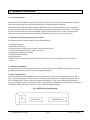
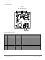
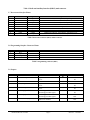
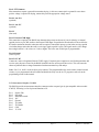
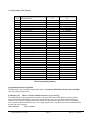
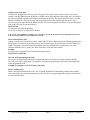
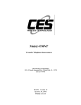
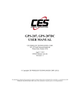
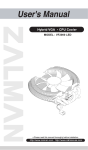
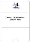
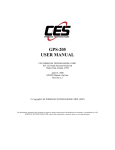
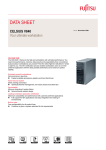
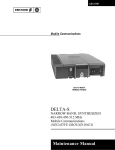
Model RM-20 Repeater Maker plus CES Wireless Technologies Corp. 925-122 South Semoran Blvd., Winter Park, FL 32792 (407) 679-9440 [email protected] www.ceswireless.com MAN79 Version 1.2 Updated 31-Jan-10 Printed in USA Table of Contents INTRODUCTION........................................................................................................................................................................... 3 SPECIFICATIONS & FEATURES ............................................................................................................................................. 5 1.0 GENERAL DESCRIPTION .................................................................................................................................................. 6 2.0 INSTALLATION INSTRUCTIONS .................................................................................................................................... 7 2.1 GENERAL INFORMATION......................................................................................................................................................... 7 2.2 MATERIAL AND EQUIPMENT REQUIRED FOR INSTALLATION................................................................................................. 7 2.3 MECHANICAL INSTALLATION ................................................................................................................................................. 7 2.4 ELECTRICAL INSTALLATION ................................................................................................................................................... 7 2.5 COMPONENT LAYOUT ............................................................................................................................................................. 8 2.6 RADIO INTERFACE CONNECTION............................................................................................................................................ 8 2.7 INTERCONNECT INTERFACE PINOUT ...................................................................................................................................... 9 2.8 PROGRAMMING INTERFACE CONNECTOR PINOUT ................................................................................................................. 9 2.9 JUMPERS .................................................................................................................................................................................. 9 2.10 RADIO AND AUXILIARY RELAY INTERFACE. J3- DB-15..................................................................................................... 10 2.11 INTERCONNECT INTERFACE J1- DB-9................................................................................................................................ 11 2.12 LEVEL ADJUSTMENTS ......................................................................................................................................................... 12 3.0 PROGRAMMING PROCEDURES ................................................................................................................................... 13 3.1 PROGRAMMING THE RM-20 ................................................................................................................................................. 13 3.2 PROGRAMMING TABLE SUMMARY ....................................................................................................................................... 14 4.2 CTCSS TONE TABLE ............................................................................................................................................................ 19 4.3 MORSE CODE TABLE ............................................................................................................................................................ 19 4.0 USER CODE CHART............................................................................................................................................................ 20 5.0 CIRCUIT DIAGRAM........................................................................................................................................................... 21 6.0 AMENDMENTS.................................................................................................................................................................... 22 CES SUPPORT 407-679-9440 Page 2 MAN79 © CES 2009 Warranty CES Wireless Technologies Corp. warrants this product to be free from defects in material and workmanship for three years from date of shipment. If such malfunction occurs, it will be repaired or replaced (at our option) without charge for materials or labor if returned to the factory. This warranty does not apply to parts damaged due to improper use- including accident, neglect, unreasonable use, and improper installation - or to unauthorized alterations or modifications of the equipment. It does not extend to damage incurred by natural causes such as lightening, fire, floods, or other such catastrophes, nor to damage caused by environmental extremes, such as power surges and or transients. It does not extend to microprocessors if is determined that the failure of a micro is due to static damage, application of improper voltages to the unit, or other problems nor related to circuit design. In such case or in the case of a desire to update the micro to a different version of software, such request must be specified in writing, and there will be a charge agreed upon by both parties. This product is warranted to meet published specification and to operate as specified only when properly installed in radio equipment which complies with US FCC specification and the applicable radio manufacturer’s specifications. CES is not responsible for any operational problems caused by system design, outside interference, or improper installation. Installation and programming of this CES product must be completed by a qualified two-way radio technician or engineer. Equipment for repair may be returned to the factory, freight prepaid, only with prior authorization. Please call 407679-9440 for an RMA number. A brief letter describing the nature of the defect should be included with the merchandise. Repair by other than CES will void this guarantee. In-warranty merchandise must be shipped, freight prepaid, to CES. CES will return the repaired or replaced equipment to purchaser, within the United States. This warranty applies to the original purchaser of the equipment only. CES is not liable under this warranty, or any implied warranty, for loss of use or for other consequential loss or damage experienced by the purchaser. Some states do not permit the exclusion or limitation of implied warranties or consequential damages. This warranty provides special legal rights, and the purchaser may have other rights that vary from state to state. Copyright The information in this manual, and any software in this product remains the property of CES. Reproduction, duplication, or disclosure is not permitted without the prior written consent of CES. CES reserves the right to change products, specifications, and installations data at any time, without notice. All information contained in this document is carefully prepared and offered in good faith as a guide in the installation, operation, use and servicing of our products. Installers must insure that the final installation operates satisfactory, within relevant regulatory requirements. We accept no responsibility for incorrect installation. A CES PUBLICATION Copyright CES 1974-2010 Introduction CES SUPPORT 407-679-9440 Page 3 MAN79 © CES 2009 Thank you for choosing the RM-20 Repeater maker plus. This product has been carefully engineered and manufactured to provide reliable service in virtually any wireless communications system. Occasionally, particular systems may require special functions not available in standard products. Please call your CES Applications Engineer to discuss special applications to meet other needs. Because we are engaged in a program of continual product development, the specifications and descriptions outlined in this manual are subject to change. Please consult the amendment section for changes. When you call CES for support, you will be asked for the version number of this manual. A manual is shipped free with each RM-20. If you do not have a manual, we are unable to provide telephone support. Manuals can be ordered from the CES Sales Department. At CES, we strive to bring you products that meet your needs. If you have any comments about our products, manuals or service please call CES at 407 -679-9440, and thank you for your continued support. CES SUPPORT 407-679-9440 Page 4 MAN79 © CES 2009 SPECIFICATIONS & FEATURES Features: Rugged construction for harsh environments Multi-user tone panel - up to 4 user groups Cross-tone encoding supported Programmed using DTMF telephone handset or over the air Optional plug in voice delay module Power and repeat inhibit switches Auxiliary relay controlled via programmable DTMF code Benefits: Create a repeater using two transcievers Provide a backup repeater for continious duty systems Make a single/cross band repeater Provide a “portable” repeater Provide a multi user CTCSS repeater system Specifications: Dimensions: Weight: Cabinet: Voltage: Current 4 x 4 x 1.5 inch. 0.5 lb. Aluminum Extrusion 12 V DC Idle 30.7mA Transmit 90.00mA Interface Cable: 6 ft shielded 9 conductor cable and RM-20 connectors provided Potentiometers for level adjustments: Receive Audio, Transmit Audio, CTCSS Output, Courtesy Beep, COR Threshold Radio Interface Connections: Power 5.5 - 18 V DC, reverse polarity protected Ground To transceiver ground PTT Relay Normally open, closed and common, connected to microphone PTT Auxiliary relay Normally open, closed and common. For user application. RX Audio Connected to discriminator or to squelched audio if transceiver has a suitable COR, level adjustable. TX Audio Normally connected to microphone audio, level adjustable. COR Required only if RX Audio input is connected to squelched audio. Interconnect Interface Connections: PTT, RX Audio, Ground, TX Audio, COR and 12V CES SUPPORT 407-679-9440 Page 5 MAN79 © CES 2009 1.0 General Description This manual provides detailed information regarding the installation, operation, and maintenance of the CES model RM-20 Repeater Maker plus. The CES RM-20 is an advanced low cost, compact microprocessor controlled repeater controller unit that can make a repeater out of just about any two transceivers. The standard features and versatility makes this an ideal choice for commercial, industrial or amateur use. The M-20 Repeater Maker plus includes: Programmable Roger Beep Programmable disconnect time out timer with disconnect warning beeps Programmable hang time Auxiliary relay controlled with programmable DTMF string PTT relay Power, COR and PTT LED’s Power and repeat front panel switches Repeat inhibit digital input with programmable polarity Up to 4 programmable CTCSS encode/decode Internal COR (discriminator) External COR with programmable polarity External interconnect DB-9 connector (pinout compatible with 4700VP Telephone Interconnect) Programmable interconnect repeat audio function Programmable Morse code ID Internal 8 pin connector for 4700DB audio delay module Local or over the air programming Low current draw CES SUPPORT 407-679-9440 Page 6 MAN79 © CES 2009 2.0 Installation Instructions 2.1 General Information Installation of the model RM-20 should be performed by a qualified two-way radio or communications technician. Ensure that static precautions are observed and that power is not applied during installation. Shielded audio cable should be used for all audio signal line connections to the transmitter-receiver combination. Terminate ground shields at the DB9 connector only to prevent hum and noise due to ground loops. The shield at the other end of the cable must be left unconnected. The best location for the units is as close as possible to the transmitter-receiver combination, thus allowing the shielded cables and wires to be as short as possible. 2.2 Material and Equipment Required for Installation The following items are needed in order to install the model RM-20: #2 Phillips screwdriver Solder and soldering iron Service monitor or deviation meter (optional for transmitter deviation) 1/8” flat blade adjustment tool or jeweler’s screwdriver Oscilloscope or RMS meter voltmeter A DTMF telephone Handset Digital Multimeter Portable transceiver programmed with same frequencies as the receiver and transmitter interfaced with the RM-20 2.3 Mechanical Installation Place the RM-20 on any surface away from sources of extreme heat or cold. The RM-20 should be close to a good grounding system if at all possible for maximum lightning protection. 2.4 Electrical Installation Electrical installation of the model RM-20 involves connections to a radio receiver and transmitter via J3 (DB-15 male). An optional connector J2 (DB-9 female) is provided for the connection of a telephone interconnect such as the CES model 4700VP. Figure 1 shows the rear panel of the RM-20. Table 1 shows functional information for each pin of the DB-15 male on the rear panel. Table 2 shows functional information on each of the interconnect pins of the (DB-9 female) connector. And Table 3 shows the RM-20 programming jack. Fig. 1.0 RM-20 Rear Panel Diagram J1 Prog CES SUPPORT 407-679-9440 J2 Interconnect J3 Radio Interface Page 7 MAN79 © CES 2009 2.5 Component Layout Fig.2.0 RM -20 B O AR D LAY O U T J3 J1 J2 JP4 TP4 R4 0 R3 7 R2 5 R2 4 JP2 R6 9 K1 TP2 JP5 U6 U2 U3 JP7 TP3 K2 JP1 JP6 JP3 Y2 U7 TP1 U1 JP8 SW1 F1 U4 Y1 SW2 U8 U5 2.6 Radio Interface Connection Pin 1 2 3 4 5 6 7 8 9 10 11 12 13 14 15 Function PTT, NO PTT, NC AUX. COMMON TX DISABLE TX CTCSS TX AUDIO RX AUDIO GROUND PTT, COMMON AUX. NO AUX. NC NO CONNECTION COR (Channel Busy) GROUND 12 VOLTS CES SUPPORT 407-679-9440 Signal ------------------------------------------Input Output Output Input --------------------------------------------------------- Description PTT relay, normally open PTT relay, normally closed Auxiliary relay, common -35 to 35 volts, switch @ 2.5v, 47k pull up to 12v CTCSS Output to Transmitter Transmit (Repeat) audio to Transmitter Receive audio from Receiver Ground PTT relay, common Auxiliary relay, normally open Auxiliary relay, normally closed Input --------------Input -35 to 35 volts, switch @ 2.5v, 47k pull up to 12v Ground Fused & reverse polarity protected Page 8 MAN79 © CES 2009 Table 1. Radio and Auxiliary Interface (DB-15) male connector 2.7 Interconnect Interface Pinout Pin 1 2 3 4 5 6 7 8 9 Function PTT RX audio Mode Signal Input Output Input Description -35 to 35 volts, switched @ 2.5v, 47k pull up to 12v Interconnect receive audio -35 to 35 volts, switched @ 2.5v, 47k pull up to 12v Ground TX audio TX disable COR 12 volts -------------Input Input Output Output Interconnect ground Interconnect transmit audio Same as radio connector pin 4 COR and CTCSS logic, open collector, 47k pull up to 12v Interconnect 12 volts, not reverse protected Table 2 Interconnect interface (DB-9) female connector 2.8 Programming Interface Connector Pinout Pin 1 2 3 4 Function N/A Tip Ring N/A Signal Description Table 3 Programming connector (RJ11) 2.9 Jumpers Jumper No. JP1 JP2 Function Future enhancements CTCSS TX output JP3 JP4 Future enhancements RX audio input JP5 TX audio output JP6 CTCSS high pass filter JP7 CTCSS high pass filter JP8 Voice audio delay (optional) CES SUPPORT 407-679-9440 Description N/A High Z Low Z N/A High Z Low Z High Z Low Z 300 Hz high pass filter in 300 Hz high pass filter bypass 300 Hz high pass filter in 300 Hz high pass filter bypass No audio voice installed Audio voice installed Page 9 Default IN OUT OUT OUT OUT OUT IN IN Position -OUT IN -OUT IN OUT IN OUT IN IN OUT IN OUT MAN79 © CES 2009 Following are instructions for each connection and adjustment that is required by the RM-20 for proper pperation. Installation procedure will be outlined first followed by the adjustment procedures. All connections to the radio (s) are made via the rear panel DB-15 connector, and should be performed by a qualified two-way radio or communications engineer. Ensure that static precautions are observed and that power is not applied during installation. Shielded audio cable should be used for all audio signal line connections to transmitter-receiver combination. Terminate ground shields at DB-15 connector only to prevent hum and noise due to ground loops. The shield at the other end of the cable must be left unconnected. Place the unit as close as possible to the transmitterreceiver combination, thus allowing the shielded cables and wires to be as short as possible. Once the installation has been successfully completed, continue with the adjustment section of the manual. Do not program the RM-20 until all the installation and adjustments have been successfully completed. 2.10 Radio and Auxiliary relay interface. J3- DB-15 Pin 1- PTT-NO Connect to the Push to Talk of the transmitter. This is normally connected at the microphone PTT input. *** See Pin 9 (PTT Common)*** Pin 2- PTT-NC This connection is generally not used. In applications where two RM-20’s are used for cross-band applications, this contact may be used. See Figure 3.0 Pin 3- Aux. Common (optional) Pin 4- TX Disable This is an input that (when active) disables the RM-20s repeat and decode functions. This connection is typically used if two RM20 are used in a cross-band application. The active state of this input is programmable. Pin 5- CTCSS TX If CTCSS is to be used on the repeater system, this connection must be made to a suitable tone injection point in the transmitter. Consult the manual and/or schematic of your transmitter for this connection. The radios microphone audio input cannot be used for this connection. Pin 6- TX Audio This connection is normally made to the transmitter microphone high input. Pin 7- RX Audio Some consideration must be given to this input. The RM-20 must have a way to determine when there is activity on the receiver. If this input is connected to the IF detector (discriminator) output of the receiver, the RM-20s internal squelch circuit will provide the carrier detection. If a filtered or squelched audio source is used, then the internal squelch circuit will not function properly and an additional connection (External COR) will be required. Also, if it is intended for the RM-20 to decode CTCSS (Sub Audible Tone), then this input must be connected to the discriminator. Pin 8- Ground Connect this pin to the common ground on the radio. If external power supply is used, tie all the grounds together. CES SUPPORT 407-679-9440 Page 10 MAN79 © CES 2009 Pin 9- PTT Common Most transmitters require a ground for transmitter keying , in this case connect pin 9 to ground. In cases where positive voltage is required for keying, connect this pin to the appropriate voltage source. Pin 10- Aux. NO (optional) Pin 11- Aux. NC (optional) Pin 12(Not used) Pin 13- External COR Input This connection is optional. The RM-20 can determine the presents or absents of a carrier either by its internal squelch circuit (see pin7 RX Audio) or the External COR Input. If squelched or filtered audio will be used for the RX Audio connection, then this connection will be required. Connect this input to a point in the receivers squelch circuit that changes state when the radio is receiving a signal (squelch is open). This signal must be a DC change that swings between 1 volt or lower to 3 volts or higher. The active state of this input is programmable. Pin 14-Ground (same as pin 8) Pin 15- 12V DC Connect to a source of regulated, filtered 12VDC supply. If separate power supplies are used for the transmitter and receiver units, the power source for the RM-20 should be the one used to power the receiver. This will lessen the chance of problems due to voltage fluctuation when the transmitter keys and unkeys. Note: Pins 3, 10, and 11 are the auxiliary relay contacts. This programmable relay can be used to control external circuitry. A pre-programmed code will enable and disable the relay over the air. To program a code refer to the programming section in this manual. 2.11 Interconnect Interface J1- DB-9 The RM-20 provides an interconnect interface connector on the rear panel (pin by pin compatible with our model 4700VP). Following is a list of pins and functions of J1. Pin 1 Pin 2 Pin 3 Pin 4 Pin 5 Pin 6 Pin 7 Pin 8 Pin 9 Push to Talk RX Audio Interconnect mode N/C Ground TX Audio TX Disable COR 12 V DC CES SUPPORT 407-679-9440 Page 11 MAN79 © CES 2009 2.12 Level Adjustments RX Audio Inject a signal modulated with a 1 kHz tone at 4 KHz deviation into the receiver. Adjust R37 for 500 mV p-p at TP2. If this level is difficult to obtain, install or remove JP4 as follows. If level at TP2 below the 500 mV and R37 is at maximum, install JP4. If level is too sensitive at TP2 remove JP4 (factory default) and readjust. Internal COR mobile detector This adjustment sets the threshold for the RM-20s internal squelch circuit. This setting is critical for proper operation of the RM20. Apply power to the RM-20 and radios. Disable the transmitter via TX disable switch on the front panel of the RM-20. Then turn R23 clockwise until the COR LED (DS2) illuminates, then turn R23 counterclockwise just until the COR LED extinguishes. Generate carrier to the receiver and verify that COR LED illuminates when carrier is present and extinguishes when carrier is removed. The COR is now set correctly. Note: Not required if external COR is used for carrier detection TX / Repeat Audio Inject a signal modulated with a 1 kHz tone at 4 kHz deviation into the receiver, and with TP2 adjusted to 500 mV p-p (175 mV rms.) adjust R69 for 4 KHz deviation measured with a deviation meter or service monitor on the transmitter frequency. If this level is difficult to obtain, install or remove JP5 as follows. If deviation is above 4 KHz and R69 is at minimum, remove JP2 (factory default). If deviation is below 4 KHz and R69 is at maximum install JP2 and readjust. Roger Beep (if enabled) Apply and remove carrier to the receiver and listen for the beep. If adjustment is needed, repeatedly apply and remove carrier in to the receiver to activate the beep. Adjust R40 until the desired level is obtained. CTCSS RX This level is also controlled with R37 (RX audio level control) and theoretically the RX Audio adjustment procedure above should be sufficient. However in cases where not enough audio level is obtained at TP2, increasing R37 will bring this level to a reliable operating range. The microprocessor will accurately decode CTCSS from 100 mV to 2v p-p. It is suggested that the input level at TP2 be kept at between 500 to 750 mV p-p. Note: RECEIVE AUDIO MUST BE CONNECTED TO THE DISCRIMINATOR OF THE RECEIVER FOR THIS FEATURE TO OPERATE. CTCSS TX A CTCSS TX tone must be programmed prior to performing this adjustment. (Refer to the programming section on this manual). Apply carrier to the receiver and monitor the transmitter frequency. Adjust R25 for 800 Hz deviation. If this level is difficult to obtain install or remove JP2 as follows: if not enough CTCSS signal is obtained with R25 at maximum, install JP2. If the adjustment is too sensitive, remove JP2 (factory default) and readjust. CES SUPPORT 407-679-9440 Page 12 MAN79 © CES 2009 3.0 Programming Procedures 3.1 Programming the RM-20 Programming procedures The model RM-20 can be easily programmed locally with a standard DTMF telephone. Programming can also be achieved “over the air” with a DTMF microphone. Note: Programming over the air requires a program access code. This code must be programmed locally on initial installation. Local programming Local programming is accessed by plugging a DTMF telephone handset into the programming jack (J1) on the rear panel of the RM-20. To access the local program mode, turn the power off and back on and press the * (asterisk) key within two seconds of applying power to the unit. The RM-20 will generate a series of beeps to the programming telephone earpiece acknowledging the program mode entry. An easy way to insure that the * is received within 2 seconds is to have the * key pressed as power is applied, then release it as soon as the tone is heard. Over the Air programming The model RM-20 can also be programmed over the air using a DTMF microphone or a portable radio equipped with DTMF keypad. However an “over the air” program code (up to 9 digits) must be programmed into the unit. It is suggested that this code is programmed on initial installation. Once an “over the air” programming code is programmed, the RM-20 can be easily accessed and programmed over the air. Simply send the access code accompanied by carrier and monitor the transmitter frequency. If successfully entered in the program mode a series of beeps will be heard. Proceed to enter the program codes needed to be programmed by pressing each key slowly and firmly and monitor the frequency for the acknowledge tones. The programming code entry sequence is exactly the same as in local programming mode. Once the unit is programmed, press (00#) to exit the program mode. To assist the programming process, a number of confidence toned will heard. They are: Valid parameter beep One 1 KHz tone (e.g. 1#) Code accepted Five 1 KHz tones (e.g. 1#0#) Error beep Three 400 Hz tones (e.g. 80#) CES SUPPORT 407-679-9440 Page 13 MAN79 © CES 2009 3.2 Programming Table Summary Code 00 # 1# 2# 3# 4# 5# 6# 7# 8# 9# 10 # 11 # 12 # 13 # 14 # 15 # 16 # 17 # 18 # 19 # 20 # 21 # 22 # 23 # 24 # 25 # 26 # 27 # 28 # 29 # 30 # 99 # Function Exit program mode COR Source External COR polarity Roger beep CTCSS TX (tone 1) CTCSS RX (tone 1) CTCSS TX (tone 2) CTCSS RX (tone 2) CTCSS TX (tone 3) CTCSS RX (tone 3) CTCSS TX (tone 4) CTCSS RX (tone 4) CTCSS tone during hangtime CTCSS tone 1 Repeater hangtime Interconnect PTT input Interconnect PTT input polarity Interconnect mode input Interconnect output polarity Interconnect active period Interconnect repeat Morse code ID send Morse code ID interval timer TX time out timer TX time out penalty TX disable input TX disable input polarity COR Only produces CTCSS Auxiliary relay code Morse code ID (call letters) Over the air programming code Program factory default Range n/a 0 or 1 0 or 1 0~2 0 ~ 50 0 ~ 50 0 ~ 50 0 ~ 50 0 ~ 50 0 ~ 50 0 ~ 50 0 ~ 50 0 or 1 0 or 1 0~9 0 or 1 0 or 1 0 or 1 0 or 1 0 ~ 60 0~2 0~3 0 ~ 90 0 ~ 90 0 ~ 30 0 or 1 0 or 1 0~4 8 digits max. 9 digits max. 9 digits max. n/a Default value n/a 0 (discriminator) 0 (active low) 1 (enabled) 0 (disabled) 0 (disabled) 0 (disabled) 0 (disabled) 0 (disabled) 0 (disabled) 0 (disabled) 0 (disabled) 0 (disabled) 0 (disabled) 2 (2 seconds) 0 (disabled) 0 (active low) 0 (active low) 0 (active low) 3 (3 seconds) 1 (enabled) 0 (disabled) 3 (3 minutes) 2 (2 minutes) 0 (disabled) 0 (disabled) 0 (active low) 0 (disabled) (null) (null) (null) n/a Table 4 Programming Summary Programming Parameters Explained The following is a list of available programmable features. Parameters in bold letters denotes factory defaults. (00# will exit the program mode). COR Source (1#) (Means in which the RM-20 determines receiver activity) The model RM-20 can be programmed for internal or external COR. Internal COR which is the factory default requires that the RX Audio input be connected to the discriminator of the receiver. (See RX Audio description) Otherwise, the External COR input must be used and this item programmed to “External COR” To program this item enter the command code followed by a 1 or 0, (don’t forget to enter a # (pound ) key between commands and at the end of the entry sequence). 1#0# = internal 1#1# = external CES SUPPORT 407-679-9440 Page 14 MAN79 © CES 2009 External COR polarity (2#) External COR signal can be active high or active low. If this signal is normally at a low state goes to a high state when carrier is detected (receiver squelch is open), program the polarity to active high. If this signal does the opposite, program it to active low. (See Description of External COR input) To program this item enter the command code followed by a 1 or 0, (don’t forget to enter a # (pound) key between commands and the end of the entry sequence). 2#0# = active low 2#1# = active high Roger beep (3#) The courtesy beep has three programmable options: (1) A tone will be generated every time the receiver carrier goes away, (2) it also can be programmed to send a tone after one second after receiver carrier goes away or (3) can also be turned off. To program this feature enter the command code followed by a 1 or 0, (don’t forget to enter a # (pound ) key between commands and the end of the entry sequence). 3#0# = off 3#1 = on 3#2# = on with 1 second delay after receiver carrier goes away CTCSS (Continuous Tone Coded Squelch or Sub Audible Tone) The RM-20 supports up to four (4) CTCSS TX tone pairs. Within each pair a separate transmit and receive tone frequency can be programmed. For example, tone #1 can receive a specific tone and transmit the same tone or it can receive one tone and transmit a different tone. Each tone pair works independently from each other. Codes 4#, 6#, 8#, and 10# correspond to TX tones 1, 2, 3, and 4 respectively. And codes 5#, 7#, 9#, and 11# to RX tones 1, 2, 3, and 4 respectively. If all receive tones are disabled, the RM-20 will operate on COR only. Refer to tone chart in this manual for tone number and frequency. CTCSS during hangtime (12#) When this code is enabled, the RM-20 will generate a CTCSS tone for the duration of the hangtime. A CTCSS TX tone must be programmed. To program this feature enter the command code followed by a 1 or 0, ( don’t forget to enter a # (pound ) key between commands and the end of the entry sequence). 12#0# = disabled 12#1# = enabled CTCSS Tone 1 command (13#) This feature limits “over the air’ programming access to carriers with CTCSS tone 1. If this feature is enabled, programming over the air and the auxiliary relay will be inaccessible unless the codes are accompanied by the correct CTCSS tone. To enable or disable this feature, enter the command code followed by 0 or 1. (don’t forget to enter a # (pound) between commands and the end of entry sequence). 13#0# = disabled 13#1# = enabled Hang-time timer (14#) This code will control the time which the transmitter will stay keyed after COR and CTCSS (if programmed) goes away. The hangtime period can be programmed for up to nine seconds at one second intervals. To program the hangtime period enter the command code followed by number of seconds required, (don’t forget to enter a # (pound) between commands and the end of entry sequence). It can also be disabled if no hangtime is needed. The factory default for this feature is 2 seconds. 14#0# = disabled 14#2# = 2 seconds Interconnect PTT in (15#) This code is only used in applications where a telephone interconnect (Phone Patch) is used in conjunction with the RM-20. When enabled, it will control the PTT on the RM-20. This input can be programmed for active high or active low. To program this feature enter the command code followed by a 1 or 0, (don’t forget to enter a # (pound ) key between commands and the end of the entry sequence). 15#0# = disabled 15#1# = enabled CES SUPPORT 407-679-9440 Page 15 MAN79 © CES 2009 Interconnect PTT in polarity (16#) This code enables and disables the interconnect PTT input when a telephone interconnect (Phone Patch) is connected via J1. To enable this feature enter the command code followed by the 1 or 0 (don’t forget to enter a # (pound) between commands and that the end of the entry sequence. 16#0# = disabled 16#1# = enabled Interconnect mode input polarity (17#) This command is only used if an interconnect is used in conjunction with the RM-20. If an interconnect is used, connect pin 3 of J1 to the connect circuit on the interconnect and program for the proper polarity. To program this feature enter the command code followed by a 1 or 0, (don’t forget to enter a # (pound) key between commands and the end of the entry sequence). 17#0# = active low 17#1# = active high Interconnect COR out polarity (18#) This output controls the interconnect mobile detect polarity (COR). To program this feature enter the command code followed by a 1 or 0, (don’t forget to enter a # (pound) after each command and at the end of sequence). 18#0# = active low 18#1# = active high Interconnect active timer (19#) This timer will control the time period in which the RM-20 will stay inaccessible after a phone call is terminated. This code is programmable for up to 90 seconds at 1 second intervals. If cover tones are used (code 20#2# ) set this parameter to zero. To program this feature enter the command code followed by the number of seconds. (don’t forget to enter a # (pound ) key between commands and the end of the entry sequence). 19#3# = 3 seconds 19#0 through 90# = 0 through 90 seconds Interconnect repeat (20#) This parameter determines what audio is transmitted while an interconnect call is in progress. This feature consists of three programmable parameters, Enabled, Disabled or Cover Tone. When enabled, the RM-20 will transmit both (Land Line and Mobile Operator) sides of telephone interconnect audio. When Disabled, only the Land Line (Telco) audio will be transmitted .If programmed for cover tone, the RM-20 will generate a series of short beeps over the air while the mobile operator is transmitting. This serves as to indicate that the channel is in use while keeping the mobile operator side of the audio muted for privacy purposes. Note: IF COVER TONE IS ENABLED, VERIFY THAT CODE 19# (INTERCONNECT ACTIVE PERIOD) IS SET TO ZERO. IF CODE 19# IS SET TO ANYTHING OTHER THAN ZERO, THE COVER TONES WILL BE TRANSMITTED OVER THE AIR UNTIL THIS TIME EXPIRES. Morse code ID send (21#) This code controls how often the Morse code identification is sent. There are four programmable parameters in this feature, Off, Timer, COR inactive for 3 seconds, and Timer / COR inactive. When programmed for Timer the RM20 will ID at the interval that code 22# is programmed for. If programmed for COR inactive for 3 seconds, the RM20 will ID 3 seconds after COR has been inactive. Programming it for Timer/COR inactive for 3 seconds the RM20 will ID when the timer (code 22#) has expired and every time COR goes inactive for 3 seconds. 21#0# = off 21#2# = COR inactive for 3 seconds CES SUPPORT 407-679-9440 21#1# = timer 21#3# = timer and COR inactive for 3 sec. Page 16 MAN79 © CES 2009 Morse code ID time interval (22#) This command controls the time interval in which the RM-20 transmit the ID call letters. This feature is programmable for up 90 minutes at 1 minute interval (1 through 90) and up to two hours with code 22#0#. 22#0# = 2 hours 22#3# = 3 minutes Note: The initial ID will be generated at 5 minutes regardless of the time interval programmed, and at the rate on which the time interval is programmed for thereafter. TX time out timer (23#) This timer will control how long the transmitter will stay keyed continuously. This command can be programmed for up to 90 minutes at 1 minute interval and up to 2 hours with command 23#0#. 23#0# = 2 hours 23#2# = 2 minutes TX time out timer penalty (24#) The TX time out timer will control how long the RM-20 will remain inactive after the TX time out timer (Code 23#) has expired. If the RM-20 stayed keyed for the length of the TX time out timer, the unit will unkey the transmitter and will stay in the idle mode until the TX time out timer penalty has expired. Once this timer has expired the unit will switch back to normal operation. This code is programmable for no penalty or up to 30 seconds at 1 second interval. 24#0# = no penalty 24#1 through 30# = 1 through 30 seconds TX disable in (25#) This code is normally used when two RM-20’s are used for crossband application in order to keep both RM-20’s from transmitting at the same time. To program this feature enter the command code followed by a 1 or 0, ( don’t forget to enter a # (pound ) key between commands and the end of the entry sequence). 25#0# = disabled 25#1# = enabled TX disable in polarity (26#) This code controls the polarity of TX disable (code 25#) This command can be programmed for active high or active low. To program this feature enter the command code followed by a 1 or 0, ( don’t forget to enter a # (pound ) key between commands and the end of the entry sequence). 26#0# = active low 26#1# = active high COR only with CTCSS (27#) This parameter enables the generation of CTCSS when the RM-20 is in “COR Only” repeat mode. This mode is enabled by setting all CTCSS RX program locations to 0 (Off). In this mode the unit can generate (transmit) CTCSS even though it does not require CTCSS to be received. To program this feature enter the command code as follows: 0=Off 1 = CTCSS #1, 2 = CTCSS #2, 3 = CTCSS #3, 4 = CTCSS #4 Don’t forget to enter the # (pound) key between commands and the end of the entry sequence. 27#0# = Off 27#1# = Transmit CTCSS Transmit Tone 1 CES SUPPORT 407-679-9440 Page 17 MAN79 © CES 2009 Auxiliary relay code (28#) The RM-20 is equipped with a auxiliary relay. This relay can be used to control external circuitry or devices by sending a code in DTMF format to the RM-20. A DTMF code (8 digits maximum) followed by digit 1 will energize the relay and a DTMF code followed by digit 0 will de-energize the relay. The normal state of this relay is disabled. When the enable code is received, the relay will energize and remain in this condition until the disable code is received. If power is removed from the RM-20 the relay will revert to its disabled condition. To program this feature with a code of 12345678 enter the following: 28#12345678#. To control the relay enter the following: 123456781 to enable it or 123456780 to disable it Note: If code 13# is enabled, the auxiliary relay can only be accessed by the proper code accompanied by the correct CTCSS tone programmed on CTCSS RX tone1 (code 5#) Morse code ID letters (29#) A Morse code ID can be sent based on a timer, when COR /CTCSS are deactivated or both. When programming the ID call letters, each character is entered by pressing two (2) numeric keys. This code cannot exceeds 9 characters in length. To program a call letter ID enter the command code (28#) followed by the 2 numerical keys for each character followed by the # ( pound ) key. Refer to the Morse code table in this manual. Example: To program the call letters KYZJ103 enter the following sequence, 29# 52 93 03 51 10 00 30 # Over the Air Programming Code (30#) The over the air programming code must be programmed into the unit before it will work (no factory default). This code can be up to 9 digits long. To program this code enter the programming mode locally, then program the remote programming code. Example: To program a code of 1234 enter 30# 1234# Factory defaults (99#) When in the program mode and this code ( 99# ) is entered, the RM-20 will immediately load the factory default values and any previous programmed parameters will be lost. Refer to programming table summary on this manual for factory default values. CES SUPPORT 407-679-9440 Page 18 MAN79 © CES 2009 4.2 CTCSS Tone Table Tone Off 67.0 69.3 71.9 74.4 77.0 79.7 82.5 85.4 88.5 91.5 94.8 97.4 100.0 103.5 107.2 110.9 114.8 118.8 123.0 127.3 131.8 136.5 141.3 146.2 151.4 Number 0 1 2 3 4 5 6 7 8 9 10 11 12 13 14 15 16 17 18 19 20 21 22 23 24 25 Tone 156.7 159.8 162.2 165.5 167.9 171.3 173.8 177.3 179.9 183.5 186.2 189.9 192.8 196.6 199.5 203.5 206.5 210.7 218.1 225.7 229.1 233.6 241.8 250.3 254.1 Number 26 27 28 29 30 31 32 33 34 35 36 37 38 39 40 41 42 43 44 45 46 47 48 49 50 4.3 Morse Code Table Char 0 1 2 3 4 5 6 7 8 9 Code 00 10 20 30 40 50 60 70 80 90 Char A B C D E F G H I J CES SUPPORT 407-679-9440 Code 21 22 23 31 32 33 41 42 43 51 Char K L M N O P Q R S T Code 52 53 61 62 63 71 02 72 73 81 Page 19 Char U V W X Y Z Ä Á É Ü Code 82 83 91 92 93 03 37 38 39 47 Char Ñ Ö CH,S AR ERR , . / ? SPACE Code 44 45 35 07 48 16 66 46 36 94 05 MAN79 © CES 2009 4.0 User Code Chart Code 00 # 1# 2# 3# 4# 5# 6# 7# 8# 9# 10 # 11 # 12 # 13 # 14 # 15 # 16 # 17 # 18 # 19 # 20 # 21 # 22 # 23 # 24 # 25 # 26 # 27 # 28 # 29 # 30 # 99 # Function Exit program mode COR Source External COR polarity Courtesy beep CTCSS TX (tone 1) CTCSS RX (tone 1) CTCSS TX (tone 2) CTCSS RX (tone 2) CTCSS TX (tone 3) CTCSS RX (tone 3) CTCSS TX (tone 4) CTCSS RX (tone 4) CTCSS tone during Hang-time CTCSS tone 1 Repeater Hang-time Interconnect PTT input Interconnect PTT input polarity Interconnect mode input Interconnect output polarity Interconnect active period Interconnect repeat Morse code ID send Morse code ID interval timer TX time out timer TX time out penalty TX disable input TX disable input polarity COR only produces CTCSS Auxiliary relay code Morse code ID (call letters) Over the air programming code Program factory default CES SUPPORT 407-679-9440 Page 20 MAN79 © CES 2009 5.0 Circuit Diagram CES SUPPORT 407-679-9440 Page 21 MAN79 © CES 2009 6.0 Amendments Manual revised 01/31/10 5:26 PM CES SUPPORT 407-679-9440 Page 22 MAN79 © CES 2009