1
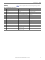
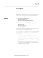
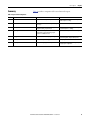
Reference Manual
PlantPAx Batch Design Considerations
Important User Information
Read this document and the documents listed in the additional resources section about installation, configuration, and
operation of this equipment before you install, configure, operate, or maintain this product. Users are required to familiarize
themselves with installation and wiring instructions in addition to requirements of all applicable codes, laws, and standards.
Activities including installation, adjustments, putting into service, use, assembly, disassembly, and maintenance are required to
be carried out by suitably trained personnel in accordance with applicable code of practice.
If this equipment is used in a manner not specified by the manufacturer, the protection provided by the equipment may be
impaired.
In no event will Rockwell Automation, Inc. be responsible or liable for indirect or consequential damages resulting from the use
or application of this equipment.
The examples and diagrams in this manual are included solely for illustrative purposes. Because of the many variables and
requirements associated with any particular installation, Rockwell Automation, Inc. cannot assume responsibility or liability for
actual use based on the examples and diagrams.
No patent liability is assumed by Rockwell Automation, Inc. with respect to use of information, circuits, equipment, or software
described in this manual.
Reproduction of the contents of this manual, in whole or in part, without written permission of Rockwell Automation, Inc., is
prohibited.
Throughout this manual, when necessary, we use notes to make you aware of safety considerations.
WARNING: Identifies information about practices or circumstances that can cause an explosion in a hazardous environment,
which may lead to personal injury or death, property damage, or economic loss.
ATTENTION: Identifies information about practices or circumstances that can lead to personal injury or death, property
damage, or economic loss. Attentions help you identify a hazard, avoid a hazard, and recognize the consequence.
IMPORTANT
Identifies information that is critical for successful application and understanding of the product.
Labels may also be on or inside the equipment to provide specific precautions.
SHOCK HAZARD: Labels may be on or inside the equipment, for example, a drive or motor, to alert people that dangerous
voltage may be present.
BURN HAZARD: Labels may be on or inside the equipment, for example, a drive or motor, to alert people that surfaces may
reach dangerous temperatures.
ARC FLASH HAZARD: Labels may be on or inside the equipment, for example, a motor control center, to alert people to
potential Arc Flash. Arc Flash will cause severe injury or death. Wear proper Personal Protective Equipment (PPE). Follow ALL
Regulatory requirements for safe work practices and for Personal Protective Equipment (PPE).
Allen-Bradley, BatchView, ControlLogix, eProcedure, FactoryTalk, Logix5000, PhaseManager, PlantPAx, Rockwell Automation, Rockwell Software, RSLogix, and Studio 5000 Logix Designer are trademarks of Rockwell Automation,
Inc.
Trademarks not belonging to Rockwell Automation are property of their respective companies.
Table of Contents
Preface
Before You Begin . . . . . . . . . . . . . . . . . . . . . . . . . . . . . . . . . . . . . . . . . . . . . . . . . . 7
Additional Resources . . . . . . . . . . . . . . . . . . . . . . . . . . . . . . . . . . . . . . . . . . . . . . . 7
Chapter 1
Overview
Design Options . . . . . . . . . . . . . . . . . . . . . . . . . . . . . . . . . . . . . . . . . . . . . . . . . . . . 9
Document Format . . . . . . . . . . . . . . . . . . . . . . . . . . . . . . . . . . . . . . . . . . . 10
Chapter 2
Unit Coordination and
Synchronization
Discussion. . . . . . . . . . . . . . . . . . . . . . . . . . . . . . . . . . . . . . . . . . . . . . . . . . . . . . .
Solutions . . . . . . . . . . . . . . . . . . . . . . . . . . . . . . . . . . . . . . . . . . . . . . . . . . . . . . . .
Controller-based Execution . . . . . . . . . . . . . . . . . . . . . . . . . . . . . . . . . . .
Server-based Execution . . . . . . . . . . . . . . . . . . . . . . . . . . . . . . . . . . . . . . .
Summary . . . . . . . . . . . . . . . . . . . . . . . . . . . . . . . . . . . . . . . . . . . . . . . . . . . . . . . .
11
12
12
12
12
Chapter 3
Operator Interaction
Discussion. . . . . . . . . . . . . . . . . . . . . . . . . . . . . . . . . . . . . . . . . . . . . . . . . . . . . . .
Solutions . . . . . . . . . . . . . . . . . . . . . . . . . . . . . . . . . . . . . . . . . . . . . . . . . . . . . . . .
eProcedure Component. . . . . . . . . . . . . . . . . . . . . . . . . . . . . . . . . . . . . . .
Operator Prompt. . . . . . . . . . . . . . . . . . . . . . . . . . . . . . . . . . . . . . . . . . . . .
Phase Request . . . . . . . . . . . . . . . . . . . . . . . . . . . . . . . . . . . . . . . . . . . . . . . .
Summary . . . . . . . . . . . . . . . . . . . . . . . . . . . . . . . . . . . . . . . . . . . . . . . . . . . . . . . .
13
14
14
15
16
17
Chapter 4
Material Management
Discussion. . . . . . . . . . . . . . . . . . . . . . . . . . . . . . . . . . . . . . . . . . . . . . . . . . . . . . .
Solutions . . . . . . . . . . . . . . . . . . . . . . . . . . . . . . . . . . . . . . . . . . . . . . . . . . . . . . . .
Controller . . . . . . . . . . . . . . . . . . . . . . . . . . . . . . . . . . . . . . . . . . . . . . . . . . .
FactoryTalk Batch Material Manager . . . . . . . . . . . . . . . . . . . . . . . . . .
Summary . . . . . . . . . . . . . . . . . . . . . . . . . . . . . . . . . . . . . . . . . . . . . . . . . . . . . . . .
19
20
20
20
21
Chapter 5
Process Upsets
Discussion. . . . . . . . . . . . . . . . . . . . . . . . . . . . . . . . . . . . . . . . . . . . . . . . . . . . . . .
Solutions . . . . . . . . . . . . . . . . . . . . . . . . . . . . . . . . . . . . . . . . . . . . . . . . . . . . . . . .
Active State Processing. . . . . . . . . . . . . . . . . . . . . . . . . . . . . . . . . . . . . . . .
Phase Failures . . . . . . . . . . . . . . . . . . . . . . . . . . . . . . . . . . . . . . . . . . . . . . . .
Summary . . . . . . . . . . . . . . . . . . . . . . . . . . . . . . . . . . . . . . . . . . . . . . . . . . . . . . . .
Rockwell Automation Publication PROCES-RM008A-EN-P - October 2014
23
24
24
24
25
3
Table of Contents
Chapter 6
Transitions
Discussion . . . . . . . . . . . . . . . . . . . . . . . . . . . . . . . . . . . . . . . . . . . . . . . . . . . . . . .
Solutions . . . . . . . . . . . . . . . . . . . . . . . . . . . . . . . . . . . . . . . . . . . . . . . . . . . . . . . .
Procedure Transition Expressions . . . . . . . . . . . . . . . . . . . . . . . . . . . . . .
Evaluation Phase . . . . . . . . . . . . . . . . . . . . . . . . . . . . . . . . . . . . . . . . . . . . .
Phase Recipe Parameter . . . . . . . . . . . . . . . . . . . . . . . . . . . . . . . . . . . . . . .
Summary . . . . . . . . . . . . . . . . . . . . . . . . . . . . . . . . . . . . . . . . . . . . . . . . . . . . . . . .
27
27
27
28
28
28
Chapter 7
Batch Timing
Discussion . . . . . . . . . . . . . . . . . . . . . . . . . . . . . . . . . . . . . . . . . . . . . . . . . . . . . . .
Solutions . . . . . . . . . . . . . . . . . . . . . . . . . . . . . . . . . . . . . . . . . . . . . . . . . . . . . . . .
Controller-based Execution . . . . . . . . . . . . . . . . . . . . . . . . . . . . . . . . . . .
Server-based Execution. . . . . . . . . . . . . . . . . . . . . . . . . . . . . . . . . . . . . . . .
Summary . . . . . . . . . . . . . . . . . . . . . . . . . . . . . . . . . . . . . . . . . . . . . . . . . . . . . . . .
29
29
29
29
30
Chapter 8
Resource Arbitration and Allocation
Discussion . . . . . . . . . . . . . . . . . . . . . . . . . . . . . . . . . . . . . . . . . . . . . . . . . . . . . . .
Solutions . . . . . . . . . . . . . . . . . . . . . . . . . . . . . . . . . . . . . . . . . . . . . . . . . . . . . . . .
Controller-based Execution . . . . . . . . . . . . . . . . . . . . . . . . . . . . . . . . . . .
Server-based Execution. . . . . . . . . . . . . . . . . . . . . . . . . . . . . . . . . . . . . . . .
Summary . . . . . . . . . . . . . . . . . . . . . . . . . . . . . . . . . . . . . . . . . . . . . . . . . . . . . . . .
31
31
31
31
32
Chapter 9
Shared Phases
Discussion . . . . . . . . . . . . . . . . . . . . . . . . . . . . . . . . . . . . . . . . . . . . . . . . . . . . . . .
Solutions . . . . . . . . . . . . . . . . . . . . . . . . . . . . . . . . . . . . . . . . . . . . . . . . . . . . . . . .
Unshared Phases. . . . . . . . . . . . . . . . . . . . . . . . . . . . . . . . . . . . . . . . . . . . . .
Shared Phases . . . . . . . . . . . . . . . . . . . . . . . . . . . . . . . . . . . . . . . . . . . . . . . .
Summary . . . . . . . . . . . . . . . . . . . . . . . . . . . . . . . . . . . . . . . . . . . . . . . . . . . . . . . .
33
33
33
33
34
Chapter 10
Two- or Three-layer Model
4
Discussion . . . . . . . . . . . . . . . . . . . . . . . . . . . . . . . . . . . . . . . . . . . . . . . . . . . . . . .
Solutions . . . . . . . . . . . . . . . . . . . . . . . . . . . . . . . . . . . . . . . . . . . . . . . . . . . . . . . .
Two-layer Model . . . . . . . . . . . . . . . . . . . . . . . . . . . . . . . . . . . . . . . . . . . . .
Three-layer Model . . . . . . . . . . . . . . . . . . . . . . . . . . . . . . . . . . . . . . . . . . . .
Summary . . . . . . . . . . . . . . . . . . . . . . . . . . . . . . . . . . . . . . . . . . . . . . . . . . . . . . . .
Rockwell Automation Publication PROCES-RM008A-EN-P - October 2014
35
35
35
35
36
Table of Contents
Chapter 11
Implementation Techniques
Standard Phases. . . . . . . . . . . . . . . . . . . . . . . . . . . . . . . . . . . . . . . . . . . . . . . . . .
Initiate . . . . . . . . . . . . . . . . . . . . . . . . . . . . . . . . . . . . . . . . . . . . . . . . . . . . . .
Timing . . . . . . . . . . . . . . . . . . . . . . . . . . . . . . . . . . . . . . . . . . . . . . . . . . . . . .
Prompt . . . . . . . . . . . . . . . . . . . . . . . . . . . . . . . . . . . . . . . . . . . . . . . . . . . . . .
Process Control/Device Ownership . . . . . . . . . . . . . . . . . . . . . . . . . . . . . . .
Mode . . . . . . . . . . . . . . . . . . . . . . . . . . . . . . . . . . . . . . . . . . . . . . . . . . . . . . . . . . .
Naming Conventions . . . . . . . . . . . . . . . . . . . . . . . . . . . . . . . . . . . . . . . . . . . .
Recipe and Report Parameters . . . . . . . . . . . . . . . . . . . . . . . . . . . . . . . . .
Phase . . . . . . . . . . . . . . . . . . . . . . . . . . . . . . . . . . . . . . . . . . . . . . . . . . . . . . . .
Procedure, Unit Procedure, Operation . . . . . . . . . . . . . . . . . . . . . . . . .
Reset/Idle State . . . . . . . . . . . . . . . . . . . . . . . . . . . . . . . . . . . . . . . . . . . . . . . . . .
37
37
37
38
38
38
39
39
39
40
40
Appendix A
Unit Coordination - Material Transfer Unit Transfers . . . . . . . . . . . . . . . . . . . . . . . . . . . . . . . . . . . . . . . . . . . . . . . . . . . 42
Multiple Transfers between Units . . . . . . . . . . . . . . . . . . . . . . . . . . . . . 43
Connections and Controllers. . . . . . . . . . . . . . . . . . . . . . . . . . . . . . . . . . 44
Misalignment . . . . . . . . . . . . . . . . . . . . . . . . . . . . . . . . . . . . . . . . . . . . . . . . 47
Appendix B
Illustrated Shared Phases
Reducing Controller Code. . . . . . . . . . . . . . . . . . . . . . . . . . . . . . . . . . . . . . . . 49
Rockwell Automation Publication PROCES-RM008A-EN-P - October 2014
5
Table of Contents
Notes:
6
Rockwell Automation Publication PROCES-RM008A-EN-P - October 2014
Preface
This document provides guidance on selected batch implementation topics
in a Rockwell Automation PlantPAx® system environment. The information
helps one make informed decisions when implementing projects by using
FactoryTalk® Batch, LBSM, or other batch management solutions.
This document is not a batch tutorial, product user manual, or programming
guide. You need to be ‘batch literate’, possessing an understanding of appropriate
industry practices, standards, and Rockwell Automation products.
Before You Begin
A sound understanding of the current parts of the ISA-88 batch processing
control standards is necessary, including the following:
• ANSI/ISA-88.01-2010 Batch Control Part 1: Models and terminology
• ANSI/ISA-88.00.02-2001 Batch Control Part 2: Data structures and
guidelines for languages
We also suggest knowledge of the following:
• How to use FactoryTalk Batch equipment editor, recipe editor,
eProcedure®, and MaterialManager components.
• How to program Logix5000™ controllers with RSLogix™ 5000 software or
the Studio 5000 Logix Designer™ application.
• How to use Rockwell Automation® process library objects.
Additional Resources
These documents contain additional information concerning related products
from Rockwell Automation.
Resource
Description
PlantPAx Process Automation System Reference Manual,
publication PROCES-RM001
Provides characterized recommendations for
implementing your PlantPAx system.
PlantPAx Process Automation System Selection Guide,
publication PROCES-SG001
Provides basic definitions of system elements and sizing
guidelines for procuring a PlantPAx system.
PlantPAx System Application Templates Quick Start,
publication PROCES-QS001
Describes how to configure controller and HMI
templates to start development of your
PlantPAx system.
FactoryTalk Batch User's Guide, publication BATCH-UM011
Provides a complement of FactoryTalk recipe
management, component guidelines, and software
installation procedures.
PhaseManager™ User Manual, publication LOGIX-UM001
Explains how to define a state model for your
equipment and develop equipment phases.
Logix5000 Controllers Design Considerations Reference
Manual, publication 1756-RM094
Details how to design and optimize Logix5000
controller applications.
You can view or download publications at
http:/www.rockwellautomation.com/literature/. To order paper copies of
technical documentation, contact your local Allen-Bradley distributor or
Rockwell Automation sales representative.
Rockwell Automation Publication PROCES-RM008A-EN-P - October 2014
7
Preface
Notes:
8
Rockwell Automation Publication PROCES-RM008A-EN-P - October 2014
Chapter
1
Overview
FactoryTalk Batch software enables you to develop batch control systems that
support your flexible production needs. FactoryTalk Batch development tools let
you define equipment configurations and then build product recipes against that
defined equipment.
Key to successful batch implementation is careful design and separation of the
batch process into two models:
• Equipment
• Procedural
The Equipment model is a hierarchical organization of the equipment and basic
control capabilities of the plant. The Equipment model is a representation of the
plant’s equipment capabilities to make product.
The Procedural model describes a multi-tiered, hierarchical model that defines
the process capability and automation control in relation to the physical model to
perform a task. The procedural model is a representation of how to use the
equipment (described by the model) to make product.
Proper design of your batch process by using these two models provides many
benefits, including providing modularity to make the system easier to design,
implement, and maintain. ISA-88 provides definition of these two models and
there are many experts and resources available in the field to provide practical
guidance of designing and implementing these models; this is not within the
scope of this document.
Design Options
Once the model is developed, there are specific implementation choices that can
also impact the success of the project. Unlike the modeling effort, these
implementation choices are often specific to the platform being deployed. The
purpose of this document is to provide technical guidance on these topics to help
you make well-informed decisions when implementing projects by using
FactoryTalk Batch software.
This document does not dictate the choice for you. Detailed, specific
recommendations cannot be made without an understanding of requirements as
they relate to the equipment capability, procedural requirements, and workflow
related to respective projects.
Rockwell Automation Publication PROCES-RM008A-EN-P - October 2014
9
Chapter 1
Overview
The topics discussed in this document have been selected based on observations
of hundreds of batch application projects over two decades. The design
considerations presented are intended to help prevent confusion and avoid
mistakes that have negatively impacted projects.
Document Format
Each chapter in this document addresses a design or implementation choice often
encountered in batch development. Each topic opens with a discussion, followed
by potential solutions, which are summarized in a reference table.
Here is a brief description of the selected topics:
Unit Coordination and Synchronization -- Examines how asynchronous units
coordinate activity between two units to make product. Appendix A elaborates
on ‘who is my partner’ and communication methods with illustrations.
Operator Interaction -- Defines three solutions for operator interaction to
execute a batch process.
Material Management -- Describes supplemental systems that manage material
consumption and supply.
Process Upsets -- Discusses upset conditions and batch recovery methods.
Transitions -- Examines configured conditions for processing a batch.
Batch Timing -- Examines techniques for establishing timing phases.
Resource Arbitration and Allocation -- Discusses how to establish rules for
sharing resources among multiple entities.
Shared Phases -- Provides architectural considerations for using shared phases to
reduce controller code for the batch. Appendix B shows what can happen if the
host controller goes offline.
Two- or Three-layer Model -- Describes how to implement controller
organization for batches.
The document closes with an Implementation Techniques chapter that contains
tips and often over-looked items.
10
Rockwell Automation Publication PROCES-RM008A-EN-P - October 2014
Chapter
2
Unit Coordination and Synchronization
When a batch requires interaction between units, a mechanism must exist to
determine which units can participate, of those who want to participate, and of
those who are ready to participate.
Discussion
Typical scenarios of unit coordination in multi-unit batch processes include
the following:
• Bulk weigh transfer from a scale unit to a mixer unit
• Content transfer from a reactor unit to a centrifuge unit
• Start mashing in the mash tun unit only after a downstream lauter tun unit
has finished raking
A ‘transfer-in/transfer-out’ pair of phases works well when coordinating material
transfer between units while ‘synchronize’ phases accomplish alignment.
For details on unit coordination, see Appendix A on page 41.
These phases, when configured in respective unit procedures, provide the recipe
author a convenient means for specifying when actions can take place in the
procedure or transfers. Now, to complete the transaction, a ‘handshake’ is
required, between phases.
This ‘handshake’, managed by controller phase logic, communicates status such as
the following:
• ‘I'm ready to send’
• ‘I have a problem, stop the transfer’
• ‘We are both at procedural point 'x,' please continue’
• ‘I'm ready for delivery 2 of 3’
Rockwell Automation Publication PROCES-RM008A-EN-P - October 2014
11
Chapter 2
Unit Coordination and Synchronization
Solutions
Two methods for ‘handshaking’ or communicating between phases are discussed
in this section:
• Controller-based execution
• Server-based execution
Controller-based Execution
Handshaking takes place by using controller tags. Depending on the architecture,
these tags are read locally or moved between controllers by using peer-to-peer
communication mechanisms such as produce/consume or message read/write.
Server-based Execution
FactoryTalk Batch facilitates ‘handshaking’ by routing the messages between
‘message partners’. Participating phases are configured as ‘link groups’, in the
recipe. Controller-based PXRQ instructions initiate message send-and-receive
requests.
Summary
Table 1 provides a comparison of the two communication methods for
unit coordination.
Table 1 - Phase Communication Comparison
Item
Topic
Controller Based
Server Based
1
Communication method
Reading/writing to user-defined controller tags
PXRQ instructions
2
Inter-processor communication
Produce/consume tags or messaging
Transparent to phase, managed by FactoryTalk Batch
3
Unit-to-unit alignment
Coded. Could require matching of ‘unique batch ID’
Transparent to phase, managed by FactoryTalk Batch
4
Phase-to-phase alignment
Coded. Could require matching of a ‘key’ formula
parameter
Transparent to phase, managed by FactoryTalk Batch
5
Adaptability
Supports any process management solution, such as
LBSM or coded sequencers
FactoryTalk Batch must be active and managing
the batch
6
Mode
Supports operator mode or other means of
activating phases
Only functions in context of a FactoryTalk Batch
executed batch, by using a recipe configured with
‘link groups’
7
Display
Tag-based. Can display conditions and status on
any HMI display
Requires FactoryTalk Batch BatchView™ to determine
messaging status
8
Data format
Supports multiple binary, integer, and real data. No
limit on size or quantity of data exchange
Single binary flag (for example, ‘Ready’) per
PXRQ instruction
9
Data direction
Bi-directional. Phases can continuously read and
write to each other
Uni-directional. A phase can only send or receive a
flag in a single transaction (or PXRQ instruction)
10
Architecture
Transactions require peer-to-peer controller
communication
Transactions require a functioning FactoryTalk server
12
Rockwell Automation Publication PROCES-RM008A-EN-P - October 2014
Chapter
3
Operator Interaction
Successfully engaging the batch operator is critical to system success.
Discussion
Most batch processes require operator interaction. Typical examples of operator
interaction include the following:
• Operator or hand additions
• Quality checks
• Measurements
Interaction often requires the operator to manage equipment, such as starting an
agitator, lining up valves, or actuating loops. But operator interaction is not
limited to making product, as operators often need direction for the following:
• Disassembling/cleaning /and reassembling a pump
• Kitting or staging of materials
• Setting up or changeover of a packaging line
• Confirming non-automated valve, transfer panel, and equipment lineups
Several factors influence operator interaction solutions. These conditions include
the following:
• Number of interactions or ‘prompts’ required to complete a task or batch
• Degree of automation
• HMI
• Recording and reporting operator interactions
Rockwell Automation Publication PROCES-RM008A-EN-P - October 2014
13
Chapter 3
Operator Interaction
Solutions
This section defines three solutions for operator interaction and provides a
diagram to show the physical relationship of each one.
eProcedure Component
The optional FactoryTalk eProcedure component displays operator instructions
in a web page or browser ActiveX. eProcedure supports electronic signatures and
signoffs captured in the batch journal.
Figure 1 - eProcedure Diagram
Computer or Server
Computer Client - Web Browser
FactoryTalk Batch
Server
eProcedure
Computer Client - ActiveX
eProcedure
46289
For more information, see the FactoryTalk Batch User’s Guide,
publication BATCH-UM011.
IMPORTANT
14
The three interactions that are discussed in this section do not have to be
mutually inclusive. To solve different functional requirements, we recommend
a mix of technologies as no one technology fits all.
Rockwell Automation Publication PROCES-RM008A-EN-P - October 2014
Operator Interaction
Chapter 3
Operator Prompt
The P_Prompt Add-On Instruction is included in the Rockwell Automation
Library of Process Objects. Similar to other Process objects, the P_Prompt
instruction consists of a Logix Add-On Instruction and a FactoryTalk View
global object that adds interaction to any HMI graphic.
The P_Prompt instruction works with multiple platforms, including a controller
or server-based batch solution.
Figure 2 - Operator Prompt Diagrams
Computer or Server
Computer Client - FactoryTalk View SE or ME
FactoryTalk Batch Server
Graphic
Controller
PhaseManager Phase
P_Prompt
Computer Client - FactoryTalk View SE or ME
Controller
PhaseManager Phase
Other Control
Activity
Graphic
P_Prompt
46290
For more information, see the Rockwell Automation Library of Process Objects:
Operator Prompt (P_Prompt) Reference Manual, publication SYSLIB-RM046.
Rockwell Automation Publication PROCES-RM008A-EN-P - October 2014
15
Chapter 3
Operator Interaction
Phase Request
Phase Requests are a FactoryTalk Batch product feature. Phase Requests,
triggered by phase logic, wait for an operator entered formula value. Responses
can be enumerated (such as yes/no) or values (such as water quantity – gallons or
kilograms).
Figure 3 - Phase Request Diagram
Computer or Server
FactoryTalk Batch Server
Computer Client - Active X
Graphic
Controller
PhaseManager Phase
Computer Client
FactoryTalk Batch
BatchView
46291
For more information, see Tips on Using PhaseManager with FactoryTalk Batch,
publication FTALK-WP001.
16
Rockwell Automation Publication PROCES-RM008A-EN-P - October 2014
Operator Interaction
Summary
Chapter 3
Table 2 provides a comparison of the operator interactions.
Table 2 - Operator Prompt Comparisons
Item
Topic
eProcedure Component
P_Prompt
Phase Request
1
HMI
Web browser
FactoryTalk View Site Edition (SE) or
Machine Edition (ME) software
FactoryTalk Batch BatchView or
batch Active X components in
FactoryTalk View SE software
2
Parameter display per instance
No limit to quantity or data type
Limited to four REAL or four string entry
and four binary selections
One parameter of any data type,
including enumerations
3
Reporting
Responses automatically entered into
the batch journal
Responses entered into the batch
journal as phase report parameters
Responses automatically entered into
the batch journal
4
Electronic signature
Supported within the FactoryTalk Batch
product
Requires custom FactoryTalk View
development
Not supported
5
Electronic signature
Signature signoff automatically entered
into the batch journal
Signature signoff entered into the
FactoryTalk View diagnostic log
Not supported
6
Display content
Text, photos, video, links
Text
Text
7
Controller requirements
No controller required
Requires controller and
FactoryTalk View HMI
Supports controller-based phases
8
Annunciation
Difficult to highlight active prompt
Designed for integration into graphics,
menus, bread crumbs
Can be annunciated in graphics by
using phase logic and tags
9
React to live data
Not readily supported
Live data integrates into prompt display
and response verification
Not applicable
10
Prompt from entity other than phase
(for example, EM or CM)
Not supported
Supports any interaction with operator,
batch/process/upset response
Not supported
Rockwell Automation Publication PROCES-RM008A-EN-P - October 2014
17
Chapter 3
Operator Interaction
Notes:
18
Rockwell Automation Publication PROCES-RM008A-EN-P - October 2014
Chapter
4
Material Management
All batches consume materials, therefore the system could support material
inventory, storage locations, and genealogy.
Discussion
All batch process requires material additions. Minimally, each addition requires
the following:
• What material to add (niacinamide, glycerin, raisins)
• How much to add (5.7 kg or 2 tablespoons)
• When to add
In many systems additional information is required, which includes
the following:
• How to add (by hand or with automated controls)
• Source or storage location (for example, storage tank A, warehouse sector;
C-3, silo 12)
When using materials, one encounters requirements, such as the following:
• Monitoring inventory
• Maintaining material lot and sub-lot numbers
• Storing material attributes by lot (such as fat content or percent moisture)
A recipe defines the materials, their quantities, and procedurally when they are
added. However, a recipe typically doesn’t include site physical data (for example,
storage locations) nor individual lot attributes. Therefore, supplemental systems,
beyond recipe management, are needed when encountering material
management requirements.
Rockwell Automation Publication PROCES-RM008A-EN-P - October 2014
19
Chapter 4
Material Management
Solutions
The following are two material management solutions:
• Controller
• FactoryTalk Batch Material Manager
Controller
A controller array that is augmented with a HMI graphic can meet many material
management requirements. In general, a UDT contains needed elements for lot
number, inventory, or expiration date. A ‘material centric’ UDT references
material while a ‘physical centric’ UDT references a location.
The array is sized for number of either materials or storage locations depending
on centricity. A user-developed HMI graphic displays and inputs desired data.
A controller-based solution requires design, development, and support by the
integrator and/or end-user.
FactoryTalk Batch Material Manager
Material Manager is an optional component of the FactoryTalk Batch product
suite that provides integrated material management capability. Material Manager
provides storage location and material configuration from which FactoryTalk
Batch managed batches retrieve or submit data
IMPORTANT
20
Material Manager is designed to support material usage in the batch process.
This tool normally complements, but does not replace, a site-wide inventory
management system.
Rockwell Automation Publication PROCES-RM008A-EN-P - October 2014
Material Management
Chapter 4
Table 3 provides a comparison of the two material management type solutions.
Summary
Table 3 - Material Management Type Comparison
Item
Topic
Controller Design
FactoryTalk Batch Material Manager
1
Data repository
Controller
MS-SQL database
2
Interface
HMI graphic
MS-SQL queries and display
3
Maintenance
Controller/HMI knowledge
RDB tools and procedures
4
Material management
Supports any batch management in any mode
(operator or program) initiated from any HMI)‘
Supports FactoryTalk Batch managed batches or
phases only
5
Find current location given recipe-specified material
Coded
Product feature
6
Theoretical inventory updates
Coded
Product feature
7
Real-time inventory
Readily supported from available instrumentation
Coded by using SQL and batch API
8
Plug-flow inventory
Coded
Product feature
9
Pallet inventory
Coded
Product feature
10
Deferred material specification
Supported
Not supported
11
New material or location introduction
No constraint
Requires restart of batch service
12
Material reference
Text strings
Pull-down list
13
Reporting – lot numbers
Coded by using phase report parameters
Product feature
14
Material quantities
Material centric < 20
Physical centric — no limit
No constraint
15
Location quantities
Physical centric < 20
Material centric — no limit
No constraint
Rockwell Automation Publication PROCES-RM008A-EN-P - October 2014
21
Chapter 4
Material Management
Notes:
22
Rockwell Automation Publication PROCES-RM008A-EN-P - October 2014
Chapter
5
Process Upsets
All systems, batch or otherwise, experience ‘upsets’. A successful system solution
provides the means to detect, inform, and respond to abnormal situations.
Discussion
A list of example upsets includes the following:
• Equipment (valve failed to open)
• Mode (operator owns and has locked a needed device)
• Process (solution fails to gel or batch fails to reach temperature)
• Materials (insufficient inventory to satisfy batch requirements)
• Quality (pH too high)
• Unknown (activity time out)
• Safety (reactor high pressure)
To avoid most upsets, be sure to use good process control, which protects life,
property, and product with safety systems and interlocks.
Now, after an upset has occurred and process control has done its job—bringing
the process to a safe state—what happens to the batch? Some batch responses
include the following:
• Keep all batch procedural entities (phase, operation, unit procedure,
procedure) in a running state, but with logic designed to respond, notify,
correct, and potentially recover from the upset
• Command only an impacted phase, to the ‘Holding’ state where holding
logic is then executed
• Command higher level batch procedural entities, such as an operation,
unit procedure, or procedure to ‘Hold’ that drives all subordinate entities
for that batch to ‘Holding’ then ‘Held’.
Rockwell Automation Publication PROCES-RM008A-EN-P - October 2014
23
Chapter 5
Process Upsets
Lastly, after a batch procedural entity has enacted its response, one needs to
consider recovery. Some of the possibilities include the following:
• Abort batch (drastic and unfortunate but could be the only option)
• Command batch procedural entities to the ‘Running’ state
• Automatically resume processing once upset is corrected
Recovery methods vary and are influenced by these factors:
• Workstation capability
• Number of operator ‘key clicks’
• Security or authentication (for example, ‘only a supervisor can
resume batch’)
• Logging and reporting requirements
Solutions
Solutions are numerous and vary based on the conditions and scenarios presented
above. This document describes two approaches:
• Active State Processing
• Phase Failures
Active State Processing
Active state processing detects, responds, annunciates, and recovers all within the
state (running, holding, stopping) where the upset occurs.
Phase Failures
‘Phase failures’ leverage the FactoryTalk Batch product and associated
configuration. Upsets, detected by controller phase logic, are read by the
FactoryTalk Batch service. The FactoryTalk Batch service then commands batch
procedural entities to ‘Holding’.
FactoryTalk Batch propagation configuration determines whether a phase, the
operation containing the phase, the unit procedure containing the operation, or
the batch is held.
For more information, see the FactoryTalk Batch User’s Guide,
publication BATCH-UM011.
24
Rockwell Automation Publication PROCES-RM008A-EN-P - October 2014
Process Upsets
Summary
Chapter 5
Table 4 provides a comparison of the two solutions for upsets.
Table 4 - Upset Solution Comparison
Item
Topic
Active State
Phase Failures
1
Architecture
Controller handles all upset activity
Requires FactoryTalk Batch Service to detect upset and
command phase to ‘Holding’
2
Architecture
Phase remains active to assist with upset handling
or recovery
Phase transitions to ‘Held,’ an inactive state
3
Architecture
Supports any batch management (example, LBSM)
and phases running in operator mode
Only the FactoryTalk Batch server can detect upset
and command phases to ‘Holding’
4
Reporting
Can be tied to FactoryTalk Alarm and Event. Batch
journal entities can be made by using a report
parameter and PXRQ instruction
Upset is automatically entered into the batch journal
5
Propagation
Requires additional controller programming
Batch service propagates ‘Hold’ to other, configured,
batch entities (phases, unit procedures, batch)
6
Recovery
Recovers from any HMI user graphic
Recovery requires BatchView Client or Batch ActiveX
7
Recovery
Automatic or single graphic button press
Can require many ‘key-clicks’ depending on recipe
and propagation configuration
Rockwell Automation Publication PROCES-RM008A-EN-P - October 2014
25
Chapter 5
Process Upsets
Notes:
26
Rockwell Automation Publication PROCES-RM008A-EN-P - October 2014
Chapter
6
Transitions
Batch procedure execution is dependent on configured conditions. Examining
and ‘going on’ based on a condition is only part of the story. Successful
solutions also consider the recipe author's effort and operator discernment
during the batch.
Discussion
Process conditions are often factored into the batch process, for example, ‘Add
Material y' only after the temperature is above 'x' degrees.
IMPORTANT
Solutions
Recipe configurations are for conditions that change between products, not for
equipment. Requirements such as ‘Never run the agitator until the lower
blades are covered’ do not belong in the recipe.
Three solutions for configuring product-related, process conditions, into a recipe
are the following:
• Procedure transition expressions
• An ‘Evaluation’ phase
• A phase's recipe parameter
IMPORTANT
These solutions are not mutually exclusive and you can use more than one
technique in the same project.
Procedure Transition Expressions
FactoryTalk Batch provides an expression editor for configuring transition
conditions. Conditions can reference controller ‘live data’ to tie transitions to
specific process events or states such as, ‘reactor temperature at setpoint’.
Rockwell Automation Publication PROCES-RM008A-EN-P - October 2014
27
Chapter 6
Transitions
Evaluation Phase
An ‘Evaluation’ procedural phase is added to the system and executed by the
controller (as done with most other phases). Recipe parameters such as ‘Wait
until Temperature >’ or ‘Wait until Level <‘ describe the condition. The
condition is then modified with parameter values, such as ‘60 °C’ or
‘35%’ respectively, to complete the expression.
Phase Recipe Parameter
If a process condition is ‘always’ or ‘nearly always’ evaluated for a given phase, then
the evaluation can be done within the phase's execution logic by using a recipe
configured value.
Summary
Table 5 provides a comparison of process conditions.
Table 5 - Process Condition Comparisons
Item
Topic
Transition Expression
Evaluation Phase
Phase Recipe Parameter
1
Convenience
Requires knowledge of expression
editor and unit tags
Configured in same fashion as other
phases (for example, Add or Heat)
Requires only parameter entry along
with other phase parameters
2
Display
Expression and status viewed only in
FactoryTalk Batch procedure display
(BatchView or ActiveX)
Condition and status are tags that
display on any HMI graphic
Condition and status are tags that
display on any HMI graphic
3
Versatility
New expressions or conditions can be
created as needed
Requires knowledge of process to
define a flexible phase
Works for a specific phase
requirement only
4
Parallelism
Many transition expressions, in parallel
legs, can be evaluated simultaneously
Requires additional phase instances if
simultaneous expression evaluation
is required
Not applicable
5
Architecture
Evaluated within batch service
Requires a controller for evaluation
Handled within existing phase logic
6
Deferring transition parameter values
Not supported
Supported
Supported
28
Rockwell Automation Publication PROCES-RM008A-EN-P - October 2014
Chapter
7
Batch Timing
Choose a timing solution that saves you time while at the same time provides the
correct time for your application.
Discussion
Most batch process has some need for 'timing', which generally appears as
the following:
• Mix vessel contents for 20 minutes
• Wait 40 seconds then add …
• Take sample every hour while reaction takes place
Generally, batch systems need a ‘timing’ procedural phase that can be inserted as
many times as needed into the procedure, which is the focus of this section.
IMPORTANT
Solutions
A timing phase does not preclude one from including timing recipe parameters
as part of another phase when this concept simplifies recipe construction or
matches a user methodology. For example, if one always ‘agitates for time’,
then providing timing setpoints in the agitation phase might be better than a
timing and an agitating phase configured in parallel.
The following are two procedural ‘timing’ phase solutions:
• Controller-based execution
• Server-based execution
In both cases, the recipe author configures the ‘wait time’ as formula parameters
and the phase completes when the specified time has elapsed.
Controller-based Execution
The timing phase is a controller-based phase that is implemented similar to all
other controller phases, such as ‘add water’, or ‘heat’.
Server-based Execution
The FactoryTalk Batch product supplies ‘timing’ phases for each unit.
Rockwell Automation Publication PROCES-RM008A-EN-P - October 2014
29
Chapter 7
Batch Timing
Table 6 provides a comparison of two timing phases.
Summary
Table 6 - Material Management Type Comparison
Item
Topic
Controller Based
Server Based
1
Time base (for example, wait 2 hr, 23 min,
15 s, and so forth)
Configure multiple formula parameters, such as
minute and second (2 hr, 23 min, 15 s)
Supports only one time base that can either be day,
hour, minute, or second (for example, 8495 s)
2
Display
Tag-based, integrates into any HMI graphic
Requires ActiveX
3
‘Time remaining’ display
Can show multiple units (1 hr, 8 min, 12 s remaining)
Displays single unit (4092 s remaining)
4
Quantity
Generally one instance only per unit, therefore one
‘wait’ at a point in time
Multiple, simultaneous ‘waits’ can be configured at a
point in time
5
Architecture
Requires controller
Managed at server level, no controller required
6
Coordination (for example, ‘time while at
temperature only’)
Facilitates timing coordination with other process
conditions or activity
No integration with process control or other phases
30
Rockwell Automation Publication PROCES-RM008A-EN-P - October 2014
Chapter
8
Resource Arbitration and Allocation
If there are shared resources, then arbitration and allocation for those resources
are required.
Discussion
Resources often have limited capacity and are used by multiple entities, thus
‘shared’. Examples include the following:
• Devices (tank outlet valve)
• Segments (common inlet header)
• Materials (alcohol supply)
• Equipment (dust collector)
• People (operator)
When sharing, ‘arbitration’ is needed to evaluate contention rules as well as an
‘allocation’ function for establishing ownership.
Solutions
Arbitration and allocation solutions are typically implemented as either of
the following:
• Controller-based execution
• Server-based execution
Controller-based Execution
Arbitration and allocation code is written and managed in the controller.
Tag-based ‘handshakes’ are developed to request, receive, and release
shared resources.
Server-based Execution
The FactoryTalk Batch product provides resource arbitration and allocation.
Shared resources can be defined at the unit or phase level.
Rockwell Automation Publication PROCES-RM008A-EN-P - October 2014
31
Chapter 8
Resource Arbitration and Allocation
Summary
Table 7 provides a comparison of resource and arbitration methods.
Table 7 - Resource Arbitration and Allocation Method Comparison
Item
Topic
Controller Based
Server Based
1
Development
Coded
Configured
2
Acquisition arbitration
Coded, therefore can accommodate priority batches,
queue wait time, or any algorithm, in addition to
‘first come - first serve’
First come-first serve allocation scheme
3
Capacity arbitration
(for example, resource can supply up to three users)
Supported through code development
Supported through configuration
4
Coverage
Arbitration and allocation active and managed at all
times within or outside of a batch
Supports phase activity that is only initiated and
directed by active batch service
5
Communication
Requires ‘handshake’ protocol and possibly
inter-processor communication
Transparent to phase
6
‘Hold’ state or similar response
Coded, therefore can release and reacquire resources
Phase retains resource unless resource management
coded by using PXRQ instruction
32
Rockwell Automation Publication PROCES-RM008A-EN-P - October 2014
Chapter
9
Shared Phases
A ‘Shared Phase’ is a FactoryTalk Batch feature that reduces coding while
providing arbitration and allocation. However, sometimes it is best not to share a
phase. This option can provide increased availability and flexibility without
reducing code.
Discussion
The FactoryTalk Batch product and PhaseManager software support a feature
that is known as ‘Shared Phase’. When a phase is configured as ‘shared’, the same
phase can support multiple batch units but requires only one controller instance.
In addition, the FactoryTalk Batch server arbitrates and allocates this shared
phase to one batch at a time.
Refer to Resource Arbitration and Allocation on page 31.
Shared phases arise when a phase class with multiple instances requires an
exclusive-use shared resource. An ‘Add-X’ phase, where ‘X’ is added to multiple
units, but dosed through a single flow meter is an example.
Solutions
Shared phases and their counterpart, ‘Unshared Phases’, are contrasted below.
Unshared Phases
Unshared phases are defined, developed, coded, and configured the same as other
unit phases such as ‘heat’ or ‘agitate’. There is a unique code instance of the phase
in each unit.
Shared Phases
A shared phase has one code instance, therefore leverages common phase activity.
For example, within the 'Add-X' phase one could find common logic for all units
with minor changes, such as an inlet valve, to accommodate different owners.
Rockwell Automation Publication PROCES-RM008A-EN-P - October 2014
33
Chapter 9
Shared Phases
For example, common logic in the 'Add-X' phase could be
• opening the source outlet valve,
• zeroing the flow meter,
• checking tolerances,
• logging actual quantities,
while only V101, V201, or V301 needs to be opened depending on unit.
See Appendix B on page 49 for illustrations of shared phases.
Summary
Table 8 provides a comparison of shared and unshared phases.
Table 8 - Shared and Unshared Phases Comparison
Item
Topic
Controller Based
Server Based
1
Development and maintenance
Each unit requires a code instance that needs to be
created and maintained
One code instance to develop and maintain for
all units
2
Architecture
Phase placement with unit's other phases
Single phase placement requires consideration,
particularly in distributed controller systems
3
Phase owner
Single unit, inherent to phase
Defined by allocation. FactoryTalk Batch in 'program'
mode, user in 'operator' mode
4
Shared resource capacity
Multi-use resource capability
Exclusive use resource only
5
Shared resource arbitration
Requires other arbitration means
Inherent to phase
6
Arbitration scheme
Coded, can support priority batches and other
rule sets
First-in – First-out (FIFO), maintained by FactoryTalk
Batch server
7
Shared resource allocation
Requires other allocation means
Inherent to phase
8
Allocation relinquishment
Phase can release allocation (for example, in phase
hold state)
Allocation maintained until phase returns to idle
9
Unit idiosyncrasies
Needed when encountering many variations (for
example, alarm handling)
Minimal differences between units (for example, one
or two valves)
34
Rockwell Automation Publication PROCES-RM008A-EN-P - October 2014
Chapter
10
Two- or Three-layer Model
Too little modularization is bad. Too much modularization is also bad. So how
much modularization is good?
Discussion
This section pertains only to controller implementation and organization. This
section is independent of batch management, servers, or services.
The following two architectures are prevalent in today's batch design:
• Two-layer Model
• Three-layer Model
The three-layer design was popular and needed prior to the release of
PhaseManager software. PhaseManager software eliminated the PLI and
associated phase interfaces, which then opened the door for a practical
two-layer implementation.
A mixed approach can be used in the same project, leveraging either two- or
three-layer advantages as needed.
Solutions
These two solutions have the following contrasts:
Two-layer Model
In a two-layer application, PhaseManager software hosts the Equipment Phase
(EP) and Equipment Module (EM). This is one ‘layer,’ the other ‘layer’ being
subordinate control modules (CM) and perhaps other EM's that are needed to
support the phase's activity.
Three-layer Model
PhaseManager software hosts the Equipment Phase (layer 1), which directs
Equipment Module(s) (layer 2), that commands subordinate CM's (layer 3).
Rockwell Automation Publication PROCES-RM008A-EN-P - October 2014
35
Chapter 10
Two- or Three-layer Model
Table 9 provides a comparison of architectural methods.
Summary
Table 9 - Controller Organization Comparison
Item
Topic
Two-layer Model
Three-layer Model
1
Maintenance
Two code layers to understand and troubleshoot
Three code layers to understand and troubleshoot
2
General interface
Same phase interface for batch, operator, or
other users
Two interfaces, one for the EP and another for the EM
3
Batch interface
Batch interfaces need to be skipped when running in
non-batch modes
Batch interfaces found only in EP leaving EM free of
any batch constructs
4
Structure
EM activity must conform to phase state model
EM's can be developed in any style or by using a state
model that best suits the application
5
Integration
Skid OEM needs to understand and provide ‘batch
centric’ solution with phase focus
Skid OEM provides ‘equipment centric’ EM's that are
referenced by SI developed batch phases
36
Rockwell Automation Publication PROCES-RM008A-EN-P - October 2014
Chapter
11
Implementation Techniques
This chapter provides some hints and tips for implementing FactoryTalk Batch.
Standard Phases
Every unit typically includes an instance of the following phases:
• Initiate
• Timing
• Prompt
Initiate
Typically, the ‘Initiate’ phase is the first phase in any unit procedure.
Functions for this phase include checking equipment states (example, clean or
dirty) or device mode verification (example, operator or program). Improper
conditions can be flagged and corrected or the batch aborted before any process
activity takes place on the unit.
‘Initiate,’ being the first phase in the Unit Procedure, is a good location for the
PXRQ instructions that are necessary to download the Unique and User Batch
ID's to the controller.
Timing
We recommend that all units have at least one instance of a timing phase that
provides the recipe author a mechanism of adding a ‘wait for time’ into the
procedure.
For more information, see Batch Timing on page 29.
Rockwell Automation Publication PROCES-RM008A-EN-P - October 2014
37
Chapter 11
Implementation Techniques
Prompt
We recommend that all units have at least one instance of a general prompt phase
that gives the recipe author the means of interacting with the operator anywhere
in the procedure. A general prompt phase is configurable and includes the
following capabilities:
• Display text to the operator only and wait for an acknowledgement. (For
example, ‘Confirm that the tank is clean and ready for the next batch’.)
• Display a question that can be answered with a button selection. (For
example, ‘Has the lab approved the batch?’)
• Prompt for data and accept either a numeric or string response. (For
example, ‘Sample the batch and enter the pH’.)
For more prompt details, see Operator Interaction on page 13.
Process Control/Device
Ownership
Architect the system so that a single equipment module (EM) directly controls
all devices (for example, valves, pumps) to complete its assigned task. Doing so,
minimizes handshaking that can be complex and problematic.
Consider, for example, a transfer between two units A and B, which utilizes the
outlet valve of 'A' and inlet valve of 'B’. Rather than assign ownership of the outlet
valve to 'A' and ownership of the inlet valve to 'B' and then handshake between
A and B and the EM, assign ownership and control of both valves to the EM (or
phase) and eliminate handshaking.
Mode
Mode indicates ownership. There can be one owner only and the owner only can
issue commands. For example, if a valve is in 'operator mode’, then the operator
‘owns’ and has the exclusive right to send commands, such as open and close, to
the valve. A device often has multiple users but one owner only at a time.
Because there are multiple users (for example, operator, maintenance, or
program) but one owner only, rules must be established regarding ownership
acquisition, retention, release, and override.
Rule definition can be difficult because these rules establish the system's
operating methodology and require agreement from a number of parties
including operations, quality, safety, maintenance, and engineering. Proceeding
beyond the requirements stage without rules in place can result in chaos, rework,
and unsatisfied system users.
38
Rockwell Automation Publication PROCES-RM008A-EN-P - October 2014
Implementation Techniques
Chapter 11
Batch ‘process management’ and ‘unit supervision’ are additional users
that can be considered in the rule set. We recommend these
design considerations:
• What unit resources can be acquired by an operator when a batch has
begun on the unit?
• What phase or equipment module resources can be acquired by the
operator when the phase is in the 'Running' state? Or in the 'Held' state?
Naming Conventions
We recommend the following naming conventions:
Recipe and Report Parameters
It’s essential that if you are using the PlantPAx web-based reporting package,
certain report and parameter names must follow the naming convention outlined
in the Event Archive’s User Guide as part of the FactoryTalk Batch User's Guide,
publication BATCH-UM011.
Recipe parameters are sorted alphabetically when displayed in the recipe editor
(regardless of order entry in the equipment editor). Preface parameters with a
letter (for example, a_setpoint, b_flowrate, or P01_xxx, P02_yyy) if ordering
is desired.
Phase
Because a phase is a ‘process action’, it is recommended that the name be a verb.
Remember, phases are configured and generally viewed in context so unit
descriptions are not needed in the phase name. Maintaining a consistent
verb_noun arrangement improves usability.
Some examples include the following:
• Transfer
• Add_water
• Prompt
• Agitate
Rockwell Automation Publication PROCES-RM008A-EN-P - October 2014
39
Chapter 11
Implementation Techniques
Class phase names are to be short and descriptive. Short, so that the phase name is
clearly displayed on batch displays and descriptive enough that one can easily
follow the procedure.
Recommended
Not Recommended
Comment
Transfer
Transfer_Mixer_to_Product_Storage
Name is too long. Information not needed or redundant when in context. Name
displays incorrectly.
Add_Water
Add_Sucrose
Add_Fructose
Water_Add
Sucrose_Add
Fructose_Addition
Inconsistent verb-noun arrangement; inconsistent verbs
Add_Alchohol
ADAL
Not intuitive
Procedure, Unit Procedure, Operation
Recipe entity naming conventions improve development, maintenance, and
display of recipes.
Entity
Convention
Example
Comment
Operation
Product_Unit_OP
LightRanch_MX_OP
LightRanch_PM_OP
Use a short, two- or three-letter representation
for unit
Unit procedure
Product_Unit_UP
LightRanch_MX_UP
LightRanch_PM_UP
Procedure
Product
LightRanch
Top level (1)does not carry an appendix
(1) The top level entity does not have a ‘_level,’ identifier. Therefore, if an operation or unit procedure is released as the ‘top level’ entity, then drop the _OP or _UP appendix.
Reset/Idle State
PhaseManager phases require an ‘Initial’ state configuration, the default is 'Idle’.
During controller powerup or transition from ‘Program-to-Run,’ the Logix
firmware sets all phases to the ‘Initial’ configured state, skipping all intermediate
states in the state model.
Therefore, a phase configured for ‘Initial’ state = 'Idle' is set to 'Idle’ without
executing 'Resetting' logic, if in the 'Running' state when a ‘Program -> Run’
transition occurs. The clean-up or resetting logic, expected to occur following the
'Running,’ 'Stopping’, or 'Aborting' states, is not executed and can cause the next
instance of 'Running' state logic to not behave as designed.
40
Rockwell Automation Publication PROCES-RM008A-EN-P - October 2014
Appendix
A
Unit Coordination - Material Transfer
This section examines the coordination between asynchronous units in a batch
process. Unit coordination can consist of material transfers and synchronization
among units.
Figure 4 illustrates a common batch process scenario that includes a Prep Vessel
and a Mix Tank. In general, two (or more) major pieces of equipment (known as
units) are required to manufacture a product. Typically, part of the batch is
started in one unit and completed in another unit to require a material transfer
between the two units.
Figure 4 - Prep Vessel and Mix Tank
Rockwell Automation Publication PROCES-RM008A-EN-P - October 2014
41
Appendix A
Unit Coordination - Material Transfer
Unit Transfers
Procedural control of automated and manual processes involves coordinated
material transfers between units.
Referring to Figure 4, assume the process requires material weighs in Unit A, the
Prep Vessel, and primary batching (add material, heat/cool, agitate) in Unit B,
the Mix Tank. Furthermore, the weighed material in Unit A is transferred to Unit
B at some point in Unit B’s process. Lastly, as soon as the prepped material in
Unit A is transferred to Unit B, then this Prep unit is available for weighs to begin
for a subsequent batch (sometimes referred to as ‘pre-weigh’ or
‘pre-batching’).
This arrangement requires two units
since two different batches are being
processed simultaneously (Batch 1 still
is in Unit B while Batch 2 has begun
on Unit A). The procedure for this
batch corresponds with Figure 5.
Figure 5 - Batch Procedure
Prep Unit
Procedure
Mixer Unit
Procedure
The ‘Procedure’ must consist of two
‘Unit Procedures’ and the ‘Unit
Procedures’ must be in parallel. This
structure is the only way to describe
the need for two units to make the product and handle the requirement of
multiple batches in the Process Cell at one time.
Figure 6 - Batch Phase Handshake
Prep Unit Procedure
Mixer Unit Procedure
The next consideration
is coordinating the
material transfer. The
material cannot be
transferred to Unit B
until B’s process is ready
for the material and the
transfer cannot begin
until Unit A is ready.
This is best handled
with a Transfer Out
(XFO) – Transfer In
(XFI) pair of phases.
The XFO phase is part
of Unit A’s phase set
while XFI is part of B’s.
The two phases
‘handshake’ between
themselves to
coordinate the transfer,
as indicated by the
dotted line in Figure 6.
42
Rockwell Automation Publication PROCES-RM008A-EN-P - October 2014
Unit Coordination - Material Transfer
Appendix A
Multiple Transfers between Units
The XFO-XFI pair phase combination is versatile and able to handle nearly all
transfer requirements. Often there are multiple transfers, between units, within a
given batch.
For example, if Unit A is a prep vessel and Unit B is a mix tank, there are two
different prep transfer activities between the units as shown in Figure 7. If Unit B
is not ready, Unit A holds until its partner is ready before the transfer occurs and
the next phase is completed.
Figure 7 - Multiple Unit Transfers
Prep Unit Procedure
Mixer Unit Procedure
See Connections and Controllers on page 44 to determine partnership in a
unit transfer.
Rockwell Automation Publication PROCES-RM008A-EN-P - October 2014
43
Appendix A
Unit Coordination - Material Transfer
Connections and Controllers
The dotted line in Figure 7 shows two unit transfers that occur at different stages
of the batch. This section elaborates on the dotted line by explaining how the
partners communicate with each other and specifically what is being
communicated to complete the transfer.
One degree of complexity comes from the number of partners and the
distribution of those partners within controllers across the architecture. For
example, a 1:1 (one-to-one) transfer represents one source going to only one
destination while a 3:1 (many-to-one) transfer represents three sources going to
one destination. The latter is more complex because the more possible
participants in a transfer requires aligned connections so the correct partners
are interacting.
Another degree of complexity includes the number of controllers that are
involved with the transfer. Table 10 shows how the combined number of
connections and controllers can change the dynamic of the transfer process
within your architecture.
Table 10 - Connections and Controllers
Model
Connection
Controllers
Total(1)
1:1
1
1
2
1:1
1
2
3
3:1
3
1
4
3:1
3
2
5
3:1
3
3
6
(1) Total is a simplified measurement of complexity.
Regardless of the number of participants or controllers, any unit transfer uses a
basic concept:
a. Who are my partners?
b. How do they communicate?
‘Who’ is doing the transfer and ‘how’ the message is conveyed between
the source and destination units is orchestrated by two suggested
communication methods:
• ControlLogix® tags
• FactoryTalk Batch message partners
44
Rockwell Automation Publication PROCES-RM008A-EN-P - October 2014
Unit Coordination - Material Transfer
Appendix A
Figure 8a and Figure 8b use a quadrant to show differences between the number
of partners, controllers, and methods of communication.
Figure 8a - 1:1 Source/Destination Configuration
Diagram Key
Shape
Object
Notes
Controller
ControlLogix controller
FactoryTalk Batch server
Transfer units
S => Source => ‘XFO’
D => Destination => ‘XFI’
Communication
ControlLogix = Controller tags
FactoryTalk Batch = Message partners
Inter-processor
communication
Produce/consume tag
Controllers
Triangle
S
S
2
D
D
S
1
S
D
D
FactoryTalk Batch
ControlLogix
Communication Method
46287
In the left side of the quadrant, ControlLogix tags are being used for the source
and destination units to transfer data between one and two controllers. Spanning
multiple controllers (see below, upper left corner) typically requires
inter-processor communication to coordinate which source units are transferring
to the destination unit.
In the right side of the quadrant, both architectures use the FactoryTalk Batch
server regardless of the number of controllers. The server-based approach is
useful when a greater number of controllers are added because FactoryTalk Batch
uses out-of-box functionality for associating and arbitrating partners. However, if
the server becomes unavailable, none of the units can communicate.
Figure 8b - 2:1 Source/Destination Configuration
S
S
S
Same Diagram Key applies as
shown in Figure 8a.
S
2
Controllers
D
D
Spanning Controllers
1
S
Same Server
S
S
S
D
D
ControlLogix
FactoryTalk Batch
Communication Method
Rockwell Automation Publication PROCES-RM008A-EN-P - October 2014
46288
45
Appendix A
Unit Coordination - Material Transfer
Up to this point we have discussed how infrastructure is used to facilitate
communication. Mode, handshake, and dialog are factors for pairing the units to
complete a task.
Mode determines ‘who’ is the owner that is responsible for making the transfer
(operator or program) and the degree to which those partners synchronize
their efforts.
Handshaking and dialog are types of communication to facilitate some type of
action for a transaction. The handshake is necessary so the recipient of the
transfer can verify its readiness. It also can be extended to the number of partners
that need to perform a single transaction (for example, two sources supplying
simultaneously to the same destination.) The source and destination units also
need to maintain a ‘dialog’ during the whole transfer process in the event of an
unintended consequence of a transfer.
For example, imagine several telephones on a network connection. One
telephone rings to indicate an incoming call from another telephone. If the
receiving telephone is not ready for the transmission, a busy single is exchanged.
S
S
S
No Answer
S
Completed Transfer
S - Source
D - Destination
D
D
The call is then placed to another receiver and an interaction occurs when both
parties communicate.
A batch transaction can be initiated either manually (operator) or by a program
(batch server). Typically, controller tags require unique batch IDs to make sure
the right partners are aligned at the right time. The batch server approach
automatically coordinates the partnership process.
46
Rockwell Automation Publication PROCES-RM008A-EN-P - October 2014
Unit Coordination - Material Transfer
Appendix A
Misalignment
In Figure 9, the dotted lines show XFO 1 is paired with XFI 1, and XFO 2 is
paired with XFI 2. Who and what safeguards against XFO2 transferring material
to XFI 1 (indicated by the null sign).
Figure 9 - Key Symbolizes Partnership
In Operator mode, the operator is responsible for determining the unit
alignment. In Program mode, the alignment is dependent on the selected
communication method. See Unit Coordination and Synchronization on
page 11.
If the communication method is ‘controller-based’ then a formula parameter,
called ‘key’, can be configured in both the XFO and XFI phases. The recipe
author configures the ‘key’ parameter with an integer that matches both sides of
the coordinated transfer. Lastly, controller code verifies that the key’s values
match before beginning a transfer.
If the communication method is ‘server-based’ then alignment is managed
through Link Group configuration.
Rockwell Automation Publication PROCES-RM008A-EN-P - October 2014
47
Appendix A
Unit Coordination - Material Transfer
Notes:
48
Rockwell Automation Publication PROCES-RM008A-EN-P - October 2014
Appendix
B
Illustrated Shared Phases
This appendix includes additional information and illustrations for
shared phases.
In Figure 10, there is one raw material that is being consumed by many units
(1, 2, 3). Even though transfer from the raw material source to any destination
unit is possible, in our example one transfer only can occur at a time because of
one flowmeter device.
Figure 10 - Shared Phase Example
Raw Material
‘X’
Unit 1
Unit 2
Unit 3
One method for the transfer process is to create a raw material (Add ‘X’) addition
phase in each unit. This method results in three separate instances of phase code
in the controller.
Controller
Add_X
Unit 1
Add_X
Unit 2
Three Instances of Phase Code
Add_X
Unit 3
Rockwell Automation Publication PROCES-RM008A-EN-P - October 2014
49
Appendix B
Illustrated Shared Phases
A shared phase reduces the controller code because one instance of code only
is required.
Controller
Add_X
Unit 1
Unit 2
Single Instance of Phase Code
Unit 3
However, there are architectural considerations. If a shared phase is in a
distributed system, you must determine the impact if the host controller with the
shared phase goes offline.
Controller1
Controller2
Controller3
Add_X
Phase 1
Add_X
Phase 2
Add_X
Phase 3
Phase 1
Add_X
Phase 2
Phase 3
Controller1
Controller2
Controller 3
If controller 2 is offline in the first set, controllers 1 and 3 still can add because
they each have a phase code. But, if controller 2 in the second set with the shared
phase is offline, controllers 1 and 3 cannot add.
We recommend that you consider the architecture and process requirements
(that is, process segmentation) to make an informed decision for the task that is
being performed.
50
Rockwell Automation Publication PROCES-RM008A-EN-P - October 2014
Rockwell Automation Support
Rockwell Automation provides technical information on the Web to assist you in using its products.
At http://www.rockwellautomation.com/support you can find technical and application notes, sample code, and links to
software service packs. You can also visit our Support Center at https://rockwellautomation.custhelp.com/ for software
updates, support chats and forums, technical information, FAQs, and to sign up for product notification updates.
In addition, we offer multiple support programs for installation, configuration, and troubleshooting. For more
information, contact your local distributor or Rockwell Automation representative, or visit
http://www.rockwellautomation.com/services/online-phone.
Installation Assistance
If you experience a problem within the first 24 hours of installation, review the information that is contained in this
manual. You can contact Customer Support for initial help in getting your product up and running.
United States or Canada
1.440.646.3434
Outside United States or Canada
Use the Worldwide Locator at http://www.rockwellautomation.com/rockwellautomation/support/overview.page, or contact your local
Rockwell Automation representative.
New Product Satisfaction Return
Rockwell Automation tests all of its products to help ensure that they are fully operational when shipped from the
manufacturing facility. However, if your product is not functioning and needs to be returned, follow these procedures.
United States
Contact your distributor. You must provide a Customer Support case number (call the phone number above to obtain one) to your
distributor to complete the return process.
Outside United States
Please contact your local Rockwell Automation representative for the return procedure.
Documentation Feedback
Your comments will help us serve your documentation needs better. If you have any suggestions on how to improve this
document, complete this form, publication RA-DU002, available at http://www.rockwellautomation.com/literature/.
Rockwell Automation maintains current product environmental information on its website at
http://www.rockwellautomation.com/rockwellautomation/about-us/sustainability-ethics/product-environmental-compliance.page.
Rockwell Otomasyon Ticaret A.Ş., Kar Plaza İş Merkezi E Blok Kat:6 34752 İçerenköy, İstanbul, Tel: +90 (216) 5698400
Publication PROCES-RM008A-EN-P - October 2014
Copyright © 2014 Rockwell Automation, Inc. All rights reserved. Printed in the U.S.A.