1
Contents
Ethernet Expansion Board
1
Ethernet Interface
3
Interface I/O Description
3
Status and Command Circuitry
CPU Read/Write Access
LANCE Interrupt Status
Read/Write Control Register
4
4
4
4
State Machine Control Circuitry
4
LANCE Interface
6
Ethernet Interface
6
Software Interface
Expansion Slot
On-Board Addressing
6
7
7
Contents
Interface Registers and Command
Descriptions
ID Register (Base Address
03FFFF - 03FFCO)
7
8
Software Reset
LANCE Data Latch
Status Ring Address
Control Register
LANCE Register Address and Data
Ports
8
9
9
9
10
Software Operation
10
Troubleshooting
11
I/O Cycle
Register Read/Write Cycle
Board ID Read-Only Cycle
CPU LANCE Read/Write Cycle
11
13
14
14
DMA Cycle
DMA Read/Write (Single)
DMA Read/Write (Burst)
14
15
17
Interrupt Cycle
17
Contents
Figures
1
2
3
4
5
6
7
8
9
Expansion Board Block Diagram
Ethernet State Diagram
Expansion Board Cycle Diagram
CPU non-LANCE Read-Timing
Diagram
........................... ':;:11
CPU non - L ..~.NCE lA]y-;+-=-'T';TTl;-nrr
""'.&.
Diagram
CPU LANCE Read-Timing Diagram
CPU LANCE Write-Timing
Diagram
LANCE DMA Read Cycle
LANCE DMA Write Cycle
2
12
16
18
...L ' - " " "
19
20
21
22
23
Tables
1
2
3
Ethernet IS-Pin D Connector
Expansion Slot Offset
Addresses
State Assignments
6
7
13
Ethernet Expansion Board Theory of Operation
This overview summarizes the major functions performed by the
UNIX™ PC Ethernet Expansion Board hardware. The topics covered
here include:
o
Interface I/O description
o
Status and command circuitry
o
State machine control circuitry
o
LANCE interface
o
Ethernet interface
o
Software interface
Ethernet ExPansion Board
The Ethernet Expansion Board (EEB), when plugged into an AT&T
UNIX™ PC, provides an interface to an Ethernet communications
network operating at a transfer rate of 10MB/sec. The EEB is
based on the AMD 7990 and 7992 chip set, which performs the
following functions:
o
AM7990 Local Area Network Controller for Ethernet (LANCE)
performs memory management, packet handling, error reporting,
and interface functions.
o
AM7992 Serial Interface Adapter (SIA) performs Manchester
encoding and decoding of the serial bit stream with phase
lock loop, clock recovery.
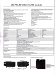
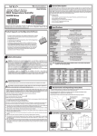
The Expansion Board, as shown in the Figure 1 block diagram, is a
circuit board containing the I/O and DMA interface to the Lm~CE
chip, a state machine with a read/write control register, a
separate DMA controller for LANCE status, and a board ID/Ethernet
address ROM.
1
XR/w*, XIOEN *
BUFFER
XRST*
EXPRQ EXPBG * XR/W* OS * INT*
BUFFER
BUFFER
STATUS
RING
ADDRESS
AND
DATA
SYSTEM
CONTROLLER
o
INT*, HOLD*, RDY*, DAS* LAS*
I"'tI
HLDA*,RDy*,DAS*, LAG*
RECEIVE
BUFFER
AMD7990
LANCE
BUFFER
TRANSMIT
~
~
Figure 1
Expansion Board Block Diagram
AMD7992
SERIAL
INTERFACE
ADAPTOR
DC-DC
CONVERTER
~COLL.,
t.- XMIT,
REC.
~
12V.
GND
Ethernet Expansion Board Theory of Operation
Once the LANCE chip is initialized, all data transfers including
buffer chaining are handled by the chip.
Timing and control are
maintained by the on-board state machine.
LANCE status is
transferred to memory by a separate state machine DMA controller
on each LANCE interrupt. This status is placed in a 256-word
ring in memory allowing the software a 256-packet interrupt
latency.
Because of maximum throughput, the CPU is able to find
all data and status in memory and never needs to talk directly to
the board. The board is also not re~~ired to wait for CPU
response or to share board resources with the CPU accesses.
LANCE operation consists of two distinct modes, transmit and
receive.
In the transmit mode, the LANCE chip directly accesses
data in memory. Data is conditioned by adding a preamble, sync
pattern, and appending a 32-bit cycle redundancy check (eRe)
This packet is sent from the LANCE to the AM7992A Serial
Interface Adapter (SIA). The SIA then transmits this packet to
the Ethernet system AM7995 transceiver.
In the receive mode,
packets are sent by the SIA to the LANCE.
Ethernet Interface
The Ethernet system, to which the EEB is connected, consists of
an external AM7995 transceiver with power supply and the Ethernet
coax transmission line. The EEB is connected to this system by
cable. For a detailed description of the Ethernet system
interface, refer to the Ethernet/IEEE 802.3 specification and
the technical manual for Local Area Network Controller AM 7990
(LANCE) by Advanced Micro Devices.
Interface I/O Descrtption
The expansion-board interface consists of drivers and receivers
for all required signals to and from the UNIX PC's expansion bus.
The expansion data bus goes through buffers that are controlled
by the state machine section to create the internal data bus.
The address bus and the bus cycle control signals are received
with buffers that are always enabled to create the internal
address and control bus. The internal address and control bus,
with the comparator for board ID, allows constant monitoring for
board I/O requests, which are then passed on to the state
machine.
For board-initiated DMA cycles, the state machine-generated
request, read/write, and data strobe signals are also driven onto
the expansion bus by this section.
3
Ethernet Expansion Board Theory of Operation
Status and Command Circuitry
The amount of on-board status and command information is limited.
The board ID function has been expanded to allow the CPU to
interrogate the board for the 6-byte Ethernet address, as well as
for the required 4-byte board ID. This information is contained
in a 32-byte prom accessed at odd byte addresses in the upper 32
bytes of the board address block. A write to any of these
addresses produces a board reset.
CPU Read/Write Access
The status and command section provides CPU read/write access to
the LANCE chip address and data ports. However, due to the long
access time of the chip, LANCE reads do not provide data to the
CPU in a single cycle. Data is latched on board during the LANCE
read; it is then read by the CPU in a separate latch read cycle.
LANCE Interrupt Status
This section contains a 16-bit register and an 8-bit counter.
The LANCE interrupt status is written automatically to memory at
the location of the combined 24-bit address by the on-board DMA.
Read/Write Control Register
A 4-bit read/write control register is also contained in this
section. This register allows the CPU to disable DMA for
diagnostic purposes, select Ethernet, and make selections between
INT 01 and INT 05. The register contains one unused bit.
State Machine Control Circuitry
The state machine control section consists of five PALs providing
control and timing signals for all other sections. A 20R8 PAL
determines when a board cycle needs to be initiated and what type
of cycle it should be. The 20R8 arbitrates between LANCE DMA
requests (HOLD), LANCE interrupts, and CPU I/O requests and
generates the LANCE HLDA and expansion bus requests as well as onboard I/O cycles.
4
Ethernet Expansion Board Theory of qperation
Each of 11 non-idle cycles has its own timing and control
requirements (see timing diagrams for more detail).
These cycles
consist of five CPU-initiated operations which are:
o
CPU non-LANCE Read
o
CPU non-LANCE Write
o
CPU LANCE Read
o
CPU LANCE Write
o
CPU Data Latch Read
These are all individual cycles that can occur only when the
state machine is in its idle state.
The state machine is always
returned to the idle state.
Three additional cycles are initiated by LANCE DMA requests.
These are:
o
request cycle
o
LANCE DMA read cycle
o
LANCE DMA write cycle
The request cycle precedes a single LANCE DMA cycle or burst of
cycles.
This cycle insures UNIX PC LANCE synchronization.
The
LAl~CE D~~ read or write cycles follow the request cycle.
Lne
state machine goes directly from the request cycle to the read or
write without going through idle. As long as the LANCE DMA
request stays active, each DMA cycle leads directly to the next,
again without idle.
LANCE DMA requests are either single cycle
for buffer management fetches or bursts of eight cycles for data
transfers.
The three final cycle types are also linked together with no
intervening idle states.
When the LANCE asserts its interrupt
the state machine executes a status LANCE read cycle reading the
LANCE interrupt status into the on-board data latch.
A status
DMA cycle is executed to place the status in the status ring in
memory.
Finally, a status LANCE write is executed to clear the
LANCE interrupt, and a CPU interrupt is generated at the same
time.
5
Ethernet Expansion Board Theory of Operation
The 20R8 PAL encodes the cycle type in 4 bits. These 4 bits are
fed to three additional registered PALS. These signals combine
with a 3-bit counter for timing within each cycle and, with
several handshake signals from the LANCE, allowing these three
PALS to generate all LANCE-related timing and control signals.
In addition, an I/O cycle signal is generated for on-board nonLANCE cycles. This signal goes to the fifth PAL. This PAL is a
nonregistered PAL that generates timing and control for on-board
I/O that is based on I/O cycle and address decodes.
LANCE Interface
The LANCE interface consists of a 16-bit, multiplexed address and
data bus with associated handshake signals. The hardware
provides three sets of 16-bit latches for address, read data, and
write data. This section also includes a buffer for the upper 5
bits of address and a 4-bit data buffer. These buffers provide
for the status write to clear the LANCE interrupt.
Ethernet Interface
The Ethernet interface is handled by the AMD chip set. The LANCE
chip sends transmit data to the 7992 and gets receive data and
collision detection from the 7992. The 7992 provides the
interface to the off-board transceiver through a standard IS-pin
D-connector interface. Table 1 lists the pin-out assignments for
this connector.
Table 1
Signal
Pin
1
2
3
4
5
GND
I
COL+
TRANS +
Not Used
RCVR+
Ethernet 15-Pin D Connector
Pin
6
7
8
9
10
Signal
GND
Not Used
Not Used
COLTRANS-
Pin
11
12
13
14
15
Signal
Not Used
RCVRPLUS12
Not Used
Not Used
Software Interface
The EEB occupies the standard 2S6Kbyte (or 128K word) block
assigned to each expansion slot.
6
Ethernet Expansion Board Theory of Operation
Expansion Slot
The expansion cards in the u~IX PC are each assigned 256K bytes
of address space.
Since all addressing is done on word
boundaries, 128K words of address space is available.
Expansion
bus address bits XAI - XA17 define this space.
Each expansion
slot contains hardwired identification bits XIDO - XID2 to define
seven unique slot addresses.
Bits XA18 - XA20 are compared
against the slot identification bits to validate the address.
Also, address bit XA21 is always zero;
similarly, expansion
addresses XA22 and XA23 are always ones.
Therefore, once the EEB is plugged into its slot, the
predetermined XA18 - XA23 bits generate the offset address, while
devices.
The offset addresses used in the UNIX PC are listed below.
Table 2
Expansion Slot Offset Addresses
Slot Number
Offset Address (h)
0
1
2
3
OCOOOOO
OC40000
OC80000
OCCOOOO
ODOOOOO
OD40000
OD80000
ODCOOOO
4
5
6
7
On-Board Addressing
Only a small number of addresses are decoded for on-board
functions.
These addresses are not fully decoded in hardware.
Undefined addresses should not be used; they may affect on-board
functions.
Reads and writes are always full words, even if only
8-bit values are significant.
Interface Registers and Command Descriptions
The following paragraphs list the registers used in Ethernet
interface operations and the command descriptions that select the
I/O functions.
7
Ethernet Expansion Board Theory of Operation
ID Register (Base Address 03FFFF - 03FFCO)
When the UNIX PC is first powered up, the UNIX kernel reads the
ID register into memory.
The ID register is a set of 8-bit
registers located at odd byte addresses in the upper 32 words of
the board address block.
The upper four words contain the
required board identification numbers.
The lowest six words
contain the board-specific Ethernet station address.
The
appropriate driver must determine where the hardware is located.
The getslot system call (see UNIX System V User's Manual,
drivers(7»
locates the offset (slot).
The base address is then
added to the offset address to access the appropriate registers.
Base Address
Description
03FFFF
03FFFE
03FFFD
R
03FFFC
03FFFB
03FFFA
R
R
R
R
R
MSB of ID, two's complement
Not Used
LSB of ID less than two's
complement
Not Used
MSB of ID
through
03FFCD
03FFCC
03FFCA
03FFC9
03FFC8
03FFC7
03FFC6
03FFC5
03FFC4
03FFC3
03FFC2
03FFCI
03FFCO
R
R
R
R
R
R
R
R
R
R
R
R
Not Used
MSB Ethernet Address
Not Used
Ethernet Address
Not Used
Ethernet Address
Not Used
Ethernet Address
Not Used
Ethernet Address
Not Used
LSB Ethernet Address
Not Used
Software Reset
A write to any of the four board ID addresses causes the board to
be reset and put into an inactive state.
Base Address
03FFFF
03FFF8
8
R/W
W
through
W
Description
Software Reset
Software Reset
Ethernet Expansion Board Theory of Operation
LANCE Data Latch
This read-only, 16-bit latch is re~~ired to acco~~odate the slow
LANCE register access time to the expansion-board timing
requirements through a two-step process. Reading the on-chip
LANCE registers does not produce valid data in time for the
active I/O cycle, but the data is stored in the LANCE data latch.
Subsequently, a read of the latch will return the desired data to
the CPU.
Base Address
000006
Description
R
LANCE Data Latch
Status Ring Address
This write-only, 16-bit register is used to supply bits A9 to A21
of the status ring address.
Bits Al to A8 are supplied by an onboard counter which is cleared on reset.
Together, they supply
the addressing for the on-board DMA to place LANCE status in
memory automatically. A write to this address clears any pending
interrupts.
Base Address
000006
Description
w
Status Ring Address
Control Register
The board contains a read/write, 4-bit control register to
provide selection of interrupt line, LAN interface type, and a
DMA disable for diagnostic purposes. This register is reset to
zeros by hardware or software reset.
Bit
Signal
Description
DO
DMAEN
1
0
DMA Enabled
DMA Disabled
D1
RESERVED
1
a
Other Selected
Ethernet Selected
1
0
Use Interrupt 01
Use Interrupt 05
D2
INTSEL
D3
SPARE
9
Ethernet Expansion Board Theory of Qperation
A read of this address also resets the board interrupt.
Base Address
R/W
000004
RW
Description
Control Register
LANCE Register Address and Data Ports
The LANCE chip in slave mode contains two ports. The register
address port is a 2-bit port that selects which of the four 16-bit
control and status ports are accessed through the register data
port.
Base Address
R/W
Description
000002
RW
LANCE Register Address Port
000000
RW
LANCE Register Data Port
Software Operation
Once the LANCE chip has been started, all data and status
transfers are done through DMA. No I/O access is permitted to
the board except the software reset and interrupt reset
functions.
10
Ethernet Expansion Board Theory of Qperation
Troubleshooting
The following procedures are a simplified description for
troubleshooting a UNIX PC Ethernet Expansion Board that is not
functioning properly or has failed a diagnostics test. The
following items are required to perform these procedures:
o
o
o
o
Kernel debugger program
An Oscilloscope
Voltmeter (VOM)
Logic Analyzer
The following reference books will also be useful:
o
Ethernet Board Installation and Diaanostics Guide
o
Advanced Micro Devices Local Area Network Controller AM799Q
(LANCE) Technical Manual
Before beginning with the troubleshooting procedures, check the
schematic against the ICs on the board so they can be identified
readily. Also, during operation of the expansion board, the
voltage at J2-13 should be 12 - 13 Vdc.
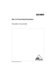
Troubleshooting is concerned with the EEB's three basic cycles
and how they relate to components that have failed.
Figure 2 is
a diagram of the Ethernet states and Table 3 lists the state
assignment functions during specific cycles. These cycles are:
o
o
o
I/O cycle
DMA cycle
Interrupt cycle
1/0 Cycle
The I/O cycle consists of three individual cycles as follows:
o
o
o
Register Read/Write cycle
Board ID Read-Only cycle
CPU LANCE Read/Write cycle
When the EEB has been reset either by a hardware or software
reset, it is at the idle state. By using the Kernel debugger
program, the I/O cycle can be examined for the three read and
write functions listed above. A failure of any of these cycles
indicates the following hardware problems:
11
Ethernet Expansion Board Theory of Operation
IDLE
Figure 2
12
Ethernet State Diay.l am
Ethernet Expansion Board Theory of Operation
Table 3
State Assignments
Cycle
3
.2
1
Function
0
0
0
0
0
IDLE
0
0
0
0
0
0
0
0
1
1
0
1
1
0
0
1
0
1
0
1
STLRD
STLWR
CPUREGRD
0
1
1
0
0
1
1
1
1
1
1
1
0
0
0
0
1
1
0
1
1
0
0
1
1
0
0
1
0
1
0
1
0
1
0
1
0
1
1
1
CPULRD
CPULWR
LDMARD
LDMAWR
STDMAWR
IORDCYC
IOWRCYC
RQCYC
Register Read/Write Cycle
A failure of this cycle is a result of a malfunctioning PAL or
wrong PAL equation, a cycle status being misread to the state
machine, or a clock failure.
The following components should be
checked for the listed conditions:
o
4B (PAL16L8A located on schematic page 4) is either
malfunctioning or the wrong equation is being read.
o
4C (PAL20R8A located on schematic page 5) is either
malfunctioning or the wrong equation is being read.
Also,
use the logic analyzer to check pins 19 - 22 for the correct
CYCO* - CYC3* sequence (refer to the cycle diagram, Figure 3) .
o
4C - 4F (PAL20R8A, PAL16R8A, PAL16R6A, and PAL16R8A located on
schematic sheet 5) are not receiving clock signals on pin 1.
13
Ethernet Expansion Board Theory of Operation
Board ID Read-Only Cycle
The following components should be checked for failure:
o
2F (PROM 748288 or 823123 located on schematic sheet 4) has
failed.
o
4B (PAL16L8A located on schematic sheet 4) has failed.
o
There is no clock present.
CPU LANCE Read/Write Cycle
The LANCE location address is being accessed by writing to the
Register Address Pointer (RAP).
The CPU LANCE Read cycle is
performed in two steps.
First, location 0000 is read; second,
location 0006 is read-returning the valid data from the address
pointed to by RAP.
If the CPU LANCE Read/Write cycle fails, check the following
components for the listed conditions:
o
4C (PAL20R8 located on schematic sheet 5) the pin 19 - 22,
CYCO* - CYC3* is not correct.
o
4E (PAL16R6A located on schematic sheet 5) is not providing
the proper signal interface (DA8* and READY*) to the LANCE.
o
4H (AM 7990 LANCE located on schematic sheet 3)
malfunctioning.
is
DMA Cycle
The DMA cycle consists of three individual cycles as follows:
o
o
o
DMA Read (single or burst) cycle
DMA Write (single or burst) cycle
8TATUS DMA Write (single) cycle
A failure of any of these cycles indicates the following hardware
problems as discussed in the following paragraphs.
14
Ethernet Expansion Board Theory of Operation
DMA Read/Write (Single)
On the first two cycles, DMA Read and DMA Write, the address is
provided by LANCE.
For STATUS DMA Write, the address comes from
the on board registers 1G and IE, and ring counters 2B and 2C,
located on schematic page 4.
These are written to during
initialization.
The LANCE performs 12 single DMA READ cycles when a 1 is being
written to the initializing bit of the LANCE control-status
register.
Using a logic analyzer, check 5D, pin 8 (RQ) located
on schematic page 4, for these 12 requests corresponding to bus
grant (BG) from 1H, pin 16 with 1A pin 12 (XR/W*) high.
111cr'\
.I. I...L.""'" '-J ,
0
0
0
0
0
check the signal
4H
4H
4H
4H
4H
pin
pin
pin
pin
pin
17
19
18
14
22
+-;YY\;Y""I"'"
'-...L..1ll...L.J.J.~
at
T J\ ....Tr~
..L..J.ILJ." v .....
as
~"...,
,
"... .. Y'~.
.LV.L.LVWi:> •
(HOLD*) schematic page 3
(HLDA*)
(LAS*)
(DAS*)
(READY*)
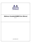
Refer to the timing diagram in Figure 3.
After initialization, LANCE generates the interrupt active low at
4H pin 11. The state machine gets the status from the LANCE and
writes to the status ring.
The content is 01C1 (see the bit
definition in the LANCE technical manual).
The state machine
then generates the interrupt to the CPU at the same time that it
writes Is to the LANCE, clearing the LANCE interrupt and status.
If the initialization is complete and correct, the status content
at the CPU memory will be 01C1.
15
Ethernet Expansion Board Theory of Operation
COMPONENT
SIGNAL
(LANCEI
HOLD*
(4CI
HLDA *
(LANCEI
LAS*
(LANCEI
DAS*
r4EI
READY *
r4CI
RQ
iCPU,
8G
~
500 ns
~
XRIW*
Figure 3
Expansion Board Cycle Diagram
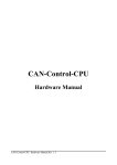
Next, the LANCE performs a single DMA read to the TMD1 every 1.6
msec.
Using the oscilloscope, check the RQ and Be activity.
Be
should have a 500 nsec pulse width. RQ should be gone 100 nsec
after Be is active.
If there is no activity (neither RQ nor BG)
check if HOLD*, HLDA*, LAS*, DAS*, READY*, and CYCO through CYC3*
are generated from 4C, located on schematic page 5.
The cycle should not be stuck at DMA Read longer than 3 us.
If
it is, this indicates that 4C and 4E on schematic page 5 or the
LANCE is defective.
16
Ethernet Expansion Board Theory of Operation
DMA Read/Write (Burst)
Using a logic analyzer, observe the DMA Read/Write burst.
The
burst should consist of a transfer of 8 words, except for the
last cycle if data is fewer than 8 words.
If the DMA Read/Write
burst does not perform properly, check 4C and 4E on schematic
page 5, or the LN~CE.
Interrupt Cycle
The interrupt cycle consists of the LANCE sending an interrupt to
the state machine at the completion of an operation.
If there is
an error, the state machine reads the LANCE status and requests
that the status DMA Write cycle be performed.
Once the state
machine gets the bus, it writes to the location of the current
status ring address and updates the status ring address.
Then
the state machine generates the interrupt to the CPU.
Note that
the status ring content normally shows whether the problem is in
either reception or transmission of data.
Check the receive or
transmit descriptor ring for further status information.
17
XO
X1
X2
X3
X4
X5
X6
X7
X8
X9
X10
X11
X13
X12
X15
X14
X16
X17
X18
X19
XO
XPCK+
~~~~___________________________________________________________________________~~
XIOEN*
XA(21:01)
~_ _ _ _ _ _ _ _ _ _ _ _ _ _ _ _ _ _ _._V_A_L_ID_A_D_DR_E_S_S_ _ _ _ _ _ _ _ _ _ _ _ _ _ _ _ _ _ _ _ _ _~
XR/W*
•
~
o
2
3
4
5
6
CYCLE END
CYCLE*
I/O READ CYCLE
XCVDIR
XCVOE*
~~---------------------------~
~-------------------------------------~~
~
XD(15:00)
____________
VA_L_I_D_D_A_TA
_____________
Figure 4
CPU non-LANCE Read-Timing Diagram
o
HI
XO
XPCKt
XIOEN*
X1
X2
X3
X4
X5
X6
X7
X9
X8
X10
X11
X12
X14
X15
X16
X17
X18
X19
XO
~
~~""""~___________________________________________•________________________________
XA(21:01)
~_ _ _ _ _ _ _ _ _ _ _ _ _ _ _ _ _ _.______________V_A_Ll_D_A_D_D_R_ES_S______________
XR/W*
~ ________________________________________________._________________
o
3
2
5
4
CYCLE*
I/O WRITE CYCLE
XCVDR
_r
XCVOE*
XD(15:00)
10CYC*
D(15:00)
---~~_________________•___________V_A__Ll_D_D_A_TA_,_ _ _ _ __
~~----------------.----------
~~U
___________________
_~,-______._ _ _ _ _ _._ _ _ _ _ _ _ _ _ _V_'A_L_ID_D_A_TA_._ _ _ _ _ _ _,
o
M
Figure 5
CPU non·-LANCE Write-TimjLng Diagram
t-.J
tT1
0
~'1
XO
X1
X2
X3
X4
CYCLE*
•
X6
X19
X18
XO
X1
X13
X14
X15
X16
X17
X18
~
CD
X19
rt
NN1JLI1NN
XPCLK+
XIOEN*
X5
•
NN
NN
~
tT1
~
~
til
NN
~.
0
~
ICYCLE
NN
~
CPU LANCE READ
NN
ENol
NN
t.'d
0
IlJ
'1
~
LCS*
~
NN
~
NN
~
0
~
LOUTLE*
NN
0
to;,
REAO*
NN
~
CD
'1
OAS*
IlJ
rt
~.
NN
REAOY*
~
NN
OAL(15:00)
Figure 6
600 OR
~
1400
0
~
~IN
NN(
VALID DATA
CPU LANCE Read-Timing Diagram
)
X2
X3
X4
X5
X6
X7
X8
X9
X10
X11
X19
X1
X11
X12
X13
X14
X15
X16
~~~'-------NN·
XIOEN*
NN0
CYCLE*
XO
ULNNJLJLNN.~LJL-
XPC LK+
~
I NN-------.-------NN.-------------~--·~~~--·-
3
2
NN
CPU LANCE WFHTE
--------------NN·---------~------·~
~
XCVOE*
XD(15:00)
tTJ
~
VALID DATA
CD
NN
m ---------------NN,-------~--------·----------·-
m
LINLE*
~
rt
tTJ
LlNOE*
~
NN --------------NN,------~-------------~
~
~
00
LCS*
fal
NN --------------NN,-------~-------------~
§
~.
to
READ*
0
Ql
1
DAS*
NN·
READY*
DAL(15:00)
..
,
600 OR
~
1
~~_ _ _ _ _ _ _ _ _ _ _ _ _ _VALID
_ _ _DATA
_ _ _ _ __
NN
NN
~
NN
NN,
NN'-NN
~
0
~
~~
0
to;,
~
CD
Figure 7
CPU LANCE Write-Timing Diagrmnl
1
Ql
rt
~.
§
Xo
X1
X3
X2
X4
X5
X6
X7
X8
X9
XPCK+
TCLK
3
I
EXPRQ*
I
EXPBG *
~
1
DAL
BUS-------+-------------<-I( _
1---75 MAX--t-LAS*
I~
29.2
~I__~II
--11+- 37.6 MAX
I
__
ADDRESS
--I ~9.2 I
>e------------':
X
DATAIN
+JI~--1
~~~~~~.,~~~--.-------------------------------------------+---------
120 MIN
_______
/+90 MAX+ 80 MIN
r.- :xi
9
M
-.j
l
DAS*
READY*
~
r-- MAX
--------------------~:--~(~------------V-A-Ll-D-A-D-DR-E-S-S-----------J)~--.I-------I------~-------I -..j
XABUS*
____________________
I
I
~'--.....L-I
I-
75-~ -I
_ __
1-'5MAX
__________~I
----------------------------------------------------------~.+~::=~~~~
15H15
MIN
XDBUS
DATA IN
MIN
------------------------------------------------------------~~~-------------------
Figure 8
LANCE DMA Read Cycle
o
HI
X5
X8
X7
X6
~
X9
XPCK'
T6
I
T2
T1
T3
:
TCLK
I -..j ~ 13.5 MAX
EXPRQ*
EXPBG *
'--'1
--~------r-:
I
T5
1
T6
I
T1
1
1
0
1
1
-1 r-_-+--_----:-~-'l
;/j.-
75
I(
~
L
_____
M_A_X-----,
LAS*
ADDRESS
90
MAX
"
+
T3
3
I
1
45 MAX
-+I r--
~29.2MAX
----~-----------------~~_________V_A_L_'D._A_D_D_R_ES_S__~
I
DATA OUP
T2
2
1
\~
DATA OUT
1
1
'>--_....:...1__
~~-------·------t-'I;
_M_'N_....:......._ _ _ _ _ _ _ _ _ _ _ _--+-
l--== 120MI~MIN
~
1
---I
---I r-I
~
------+1-------------r-~
I
I
1
1
10 MIN
8 MIN
80 M IN
-----1i
..., r---I t--
DAS*
-<
I
ADDRESS
'------
I
~~~A~N
MIN
---------------------,
J
2,7.6 MAX
_---J?-
1
DAL BUS
I
~IL1_JL.u-L~I
d
ll...-__
~
XABUS
T4
1
_~__,8 MIN
1
iFL_
--I
---I
'15 MAX
READY*
------------------------'----------:t:__~~_7_5-_25 0_~
I
--~I----
VALID DATA
~_________
~
.-/
____
-.J 1---. 26 MAX
)>--------------------«
XDBUS
VALID
DATA
OUT _ _ _
_ _DATA
____
15 MAX
~r
__
--I
r--
22.5 MAX
o
1-1)
Figure 9
:~CE
DMA Write Cycle
~
7_ _ _-.1.-_ _ _ __
1_ _ _ _ _ _
NOTES'. UNLESS
I. ALL
RE515TOR
2. ALL
VALUES
REfERE~JCE
'"
TI-lE
AQE
IN
SHOWN
f6=~=~= ::~~
'aLLOWING
C37·4(1)
I
__________~t~____
SPECIFIE.D.
OHMS
I
'4.w
I
JI- 3,6 912,15,
20,23,26
CAPACI,OR VALUES ARE IN MICROFAPADS,
3. PAGE
o
Ol>lERWI5E
C>-
AS
o
NO
COMPoNENTS
ARE
NOT USED
ON
p,ce
KI~2,P\('1) rVR2jCRl,SPRI
DEVICE
74F04-
'2.,5 .
60
---------!~~~~~~D..:_~~_
"2.--
14
6E
2,3
UlJ
1<Zl
20
10
74F24'j
IA ~2CIIF
Ic~,6
74F 373
2D. ?~£>}_~~~ 3!=J~3~~~~
.
__
741=374
i~\,=-,~
6B
74LSI25
SE
74LSI75
3B
74LSl.A4
-- .--.-
I",
~.-
lEI
~-
-
iF-----~-~
~-7F--'
dE
16
16
~
------------ -
7
B
8
-,4:--
4
:!>---~
-S
2m
REFERENCE
2(!J
1<1>
5
DALZOR3A
4C
24
12
5
I 6L6A
4B
AM79!)Q)
-LINE-~
48
~--------.-~.
6F
, !-~~.~
--~~_\~ ,a/71 ,S
14
LAST USED
OESIGNATION,;
NOT
SPARES
(EXCL
I.e,' 5 )
p~R~TliN~,~6_j~"ls__
USED
-~
_.....
--~-
-
_ ..
---_._-- . - --
Cb3
2m
ISO,
AM7992
DELAY
~----
2
7
14
4·0,41='"
xFMP
..
-I----+---
PALliQR-aA
-PAL
B
4
c
3A
74S~5
PALl6R6'"
1<Zl
2B, SF
7453'0
•
iii;
16
- 74L5393'
--~--
2
14
74LSltC,\
--
I(l)
14
74L5123
74528f1
75453~
4,2
4
20
~5~
74LS'74.
C
4
1(1)
--3--3
CRZ
QP4
E9
RP7
~I
I,
31 J .34[
KZ
67
LI
RI3
I
3~J ·~:nr42H45,
71-74,53 - 91
J2
RP8
VR2
~
A
_ _ _ ...J _ _ _ _ _ . _ _ _
A
-'-~I-
8
~
4
__________________________________________________________________________________________________________~5T~A~T~OROE •
0 BUS CD -15
PI
Jl
~-E--.-------------------4------------------------------------------------------------------------- ___________~--------------~--_,
~~~U-T--O-~E-.------------------~-----------------------------------------------------1-_____________- - ,
o
01
5:71
LOUT LE
l!
S 5C
6
I3/t _ A5M *
V 74F<Z>A
~----=~~--------------------~----~~~~~-------------~
S RP3
74F74YZ
,--_ _ _ _ _ _-'=-"Z 0
r-~-c.\(
.5
5
SO
74F<V4
~LDA
!;.
'f
;:,DA..:.:L::,:(l)"--___ :::.j3 OLE
OALI
a~-"'.c
DAL'2.
r ~L3
Q~
y.
I'!
SCI
\I
3.~K
4
L..-.;'<j--
74F7<1
I.
4
~
5c;::.o.:::."'-+---+_ _~Z"-lD
5
Q
_~
:!I.ll(
+SV
N.C
'2.0
0
~
OAL (;,
"7 D
DAL 7
D
2A
Gl~ ________ XAI
0
OAL5
II
I
OEQF----N_C.
0
_~
VOA~3
I'lPI
~
4
Q~_)(,A2
~_
XA0
~
0
V
OAL?,
e
Q~_
5D
Q~
~~_
O<I>
3 OLE
DI
4 0
Q~ ______DZ_~ __ ~
D
D
I
I
OEQ Z
__ ~ D
D3
Q~ _~L'!.../
Q~_
5F
__[)A_~
13 0
Q.
12.
04
____
D
DALS
14 0
Q
15
05
__
D
DALE>
17 0
Q
U;
DG
17 D
Q~ _ _ _[;)~'=-":/
Q~ _____.E~-'=-V
G~ _~
0.0.1.. 7
16 0
Q
19
D1
~e
Q~
G
.:;
V
".0.7
'-----74F373
I--~
~__ ~
__ ~'=.'l'../
Q~ ____ ~A~
DAL4
'---741"375
0
_i:J!'-_L_y
'--------7 .. F37e.
'---1---_ _ _ _ - - -
CLI'lAOREN.
L INLE
OEGl~
_ 1 D
Q
I
1\
DALe.
~~~30-E-.--------------------------------------~
c
OLE
4
o
~~
Q
~~B~G~-----------~----~------~3CKR Q~ __ _
5' 01
3
DALI
~~
I
~---------XA4'
~_----'X~
~ I..
---x'~
OAL<I>
DAL BUS (l)-15~
3 OLE
OEGl~_
~~~--~ 0
/~ALI~---2 0
• ~' I
B 0
/ DALlZ--..----~ D
'*' _______________________________~
~'!:..~ D
Q
DB
5
;5
Q
~
Q
DII
DI'2.
Q
15
DI3
11 D
Q
IE>
01"
0.0.1..15
18 D
0 3 ' -_ _
0
8 0
I:!. D
0
3(;
14 D
_______
1--1'7
DIS
D
'"
9
Q
c
DALIa>
DAL \I
Q~_~
G
15
DALI5
Q
I..
DAL 14
Q~_~-'V
16 D
L - - - -_
-+____7_4_F_37_3____________ - . /
______7_"_F__
3_73____________________
1-_
----------------------------------t--------,
----+,a':tG
~
I--
~---------------
,------~~~
Q~_~
4 0
09
9
12.
DALl4
---
L -____________________ - - - - - -
OEQ~--~-~~
Q~~.~I~f'.------~
3E
'-________
----------
OLE
9
A
>S'V
~~L/---
\I
CI<
I?' I'!
8
\-Ie
-:l:=-
Q 6
RP46
3:3.12
\
741"74/~
",I'lP3
.5 . .5K
r---o~
---
OEy~_l)~,=-~
Z A
H:
~
ZH
A
i<
:~--~
•'" 8
'(~_OAL_3
~y~
.sv
pO
~
r -_____________________________~S~IA=C~K~_~
'-------____ --------------4-- _________-j-_________________________
C_K_ _ _
0
~
~
9
~D
LABUSI"-Z~
~----------+-
---------~~_I~ OLE
XAI(;,
XAI7
XAIB
OEof-'2-_~
o~--'::~~
19 0
6Gl
D7
LAIB
9
12 0
D ~ ___\.:'~~~
150.
0 ~_LAZ.I
XAz'1
N.C.
~
N.C.~
Q
Q
Q
3H
0 ~ _ _'=-~~
XAIS
XAiW
Df-l
O~~ ~5V
~74F37~
A
~CLK
Q'
,-;;--R::":::T::::*=========================================-+______________ t------ ______ ~______
3_3K
A
----;::l1}-:c::-
~ CLK2.<l1
'" I
~
~ .. u,
~--------------,---------
-- -
-
~o;'''-o --
----~ - --
-j-."-
[)i____P_ -08-0<?24::'___ -00 A
i
_ _ _~_ _-------------~------_ _- L
.
L._"_ _ _ _ _~~T
I
_:-_<?~~
_
..
-~-
- - - -1
7A.F<2)A.
-'(7-----o
L
vee
o
?>c
GFJ
2.sns
74Ff36
DELA~ 8~.... ~1~Y-2.
LINt,
AM799([J
~
~
C
.
~-~---
4H
... fl!'C:.+... __--o PI
Tr
READY
GNDZ
t
-1
7
01
I
3
-----------------
____C~5_E_L____ ... _--~
- ____ D~AEN
~
__ ~
DB\!5 ([>-15
o
JI-52
JI-51
-11-47
..J1~4b
r"_ _ __
XD8
JI-BZ
~-Dg---
JI-61~
-II-BO
XDII
-I1-79~JI-7B
c
D
-11-77
XDI~
c
XDI4
JI-76~
DL~~~~~__~~~~==----===t=STATADROE ..
JI-75
XIDID
2l!?DEC.
B
EXCK
CK*
XR./w_"'_---cr ....
JI-68 c:>---'XR5T"'_ _- - .
JI-39
--------SG
1
__
~
~
__
.
.~
~
LAS~
3
BI
5
CI
A
A
~
~E~A£D~L
____________________________________ _
t
7
6
~
1
______-L ____,_
74LS393
D
D
---
~--~
147l_ DMAEN
~
- --=-0-7453B
-C>
.J1-09
c
c
~::~
~------"-
__ Ll~~~ _ _ _ ~
----~I
DI>S"
~-----74LSIZS
SE
1M
___
~
RE AD'" 11\ ____
~
B
~
-~
I
-- ;-;;-iJF~
E~--~ ~"
I~
I~
CK EN
_ ,___
___
J~::z
3_~:~
AIJR
4-
-
~-
- - --,',- ---SE
______ LCS-If
---, ..LSI2.S
----
~=_~----J%]
_ _
_______
-
____
N.C,
----
A
-
1M
[2/1
~rATWRO~- ,~ -l&~
--'------c
READL
----
---S'~DMA- __
,-ri71--~
~
A
----------1'
I
---3---r
o
o
N[) I t
~i
:
SfMflm
III
~ONCL;c;or~
MINIMUIM
MINIMUM nIRGllf'
c
14030
Cf<U-)
lil:'iUIRLII
~IDlll
a~~~
00(1
MnTE.RIr1L TO 01 melSS t-XI'()X'I IfFI fl<
1 07 ~OPP[R
PL_nTt TO ? rJl : IN tllJ'l ~ ii
MIL-P 4122", MIN 99,5
PUl<l
CIlL!lR
llr~
MElfi! CI el[) LnM:NRI( S oHm I
fl[lnRO THICKNf:';,; TO Sf
INSPU~TION
Vf_~[;CR
IN ORI;r
F)t~
P 13949
250
IPC n-630C
SHnu Sf] fer PRUCL SS, S, fUlJIDMLNT nN[)
TO RI:f'IIr',)I- zt RI) iJl I lCf PRGlJur: I
[W~~:Y;"
!3(lf)f{~;
EIG:H SlUES Of
~;~·IPLL
f3r
I
f)lI--lfR;.J~·:;f
111 L IIOLLS
f()
U~;~'~\;
F[~,'1
lRY
PC401,
SIl KSCRf:,~ CUMPUt'-,tNf SlL"lr
COl rm: .JHI rt
NOt-I- ~:[1I\J[IlH:l
UNLf-~;S
IN elC[;[)I<OnNCE WITH MIl
'/- 005 (GLelSS :0 GLnSS J
0(,7
~nrLt-(Hll_<';
I,
:;OL.l1l·-~Mf'Sr\
SOl
eRr :ERlf1
c
ri~'..j\J~[J[TJ
PK~t;I~[
r<
P~:JVII:TfJ
HOLt--S ;1Rr
PLn:·l~J
lv~
'~Ll
Jr~
>-lr~~;JOf{:\
\<;ING
SPEerl- a-Il
r1:-(~:"'::;<:\
111'_ F INI SIIUl S i i f q
It"
0°0
THR[J~;r~H
II
B
-_
t
l
[-
~;l:Il[
COlJf r DE SCI< I f' T[UN
UNMKIJ, 019' OOl
tl
~
I
I 09 l '
1?:,'
ei
fI
1?0'
0Ol'"
0t>?,
1 'i?'
IJ 03
!~~
1101
13 ~ 'J
IJ e 1
11e 3
i j,J[
Di:
'PI [1: INc;!
n
6
i
~;
YlS
NLJ
~I' :,
flo
0
0000000°00°0
0000
OE
0
g
Os 0C' 0
0 0-
DO
QOQOOOQ,}OOOOO
[]
~«
000
OOOOO'),QOOO,)000.JQ'}O:OQ.QO.CO
O
hh~'
r
II,,!
000
CE
PLn I j\jG
fiLL HOLfS SlInLL Ell L,oun!!) ,j]THU,
30] 01 Hll:R
IRUE POSIIIllN WIlli Rl!)l'lCI 10 THl PRn C[NI,J,
~IUI
~
I
,
' - ' ,__ ,
~
'- ' -
", '\,. " "- '\,. '- ,
"'--
~
6
SRO!.JN[: DLClr....:?O:..J::-:i~ ~L_,~·' .. t
SOL~[~
SI:JE
INCHES
(Nor TO SCRLE)
T
~
~
LRYfR ORIENTnTION
A
%
El
S(H :)1 R S l~ifI'; "
8
;
1
~l_~_ '\.
10
(2PL)
I
010 lH'
B
(REI )
10 X
I
LPMI"nfE
BTWN G~~C
RNL.:! Pl~wt ~
4,280
<1.533
~
'--'-----------------'
----i
5
4
r
THIRD ANGLE
PROJECTION
------r---I
A
----~-------'---------'---
o
o
lINLlSS Olc,C,<'..JlSE SPEC;Flt:O
)
\·111< COMPI,
.,
';ClH~1R~Ir:
C~j
LIST ;JF Mf1:FRIRLS SEE IJ-60-00243
i<EF
J·08~~24'
ao
30
'iii
OF
ClJf'JI'~fl~
J~JI
[;1
.~
'I)
"10Ut'Hlf'l[
, ' ' . Or
S'=:f~~':W
IS IN::)[I:(H-ii fRCM
:-ml:'<~
riFf-IX INI;[CRTED [TM~ONUn'i 10 P.C.B
;"1[_~1 :cs I ;)r
'~F TfR Wr,IJ[' SOL D[I~
c
FeJI
40
2
CD~prJl'Jl~J;S
USING HOT-MU_T
nRC NOT USCl ON THIS VERSION
c
COMPONUJT :;Illf
@/
\)IFW
-- 44 MRX
/'
(7::1
B
"" B
'"
'"
rJ
~
INCHES
UNLESSOTHERWISESPECIFIEO
DIMEHSIOHS.t.REIHIHCHI!!
A
~f:~~~~~g:!,~i~~::~~f;~ti Convergent Technologies'" -/-\::n~~~II::~D;:!~;~~II~:c~~~lrO;:I!tan
TlTL!--
Rw'ING
M
RSSt~ i-~~-~ R
[TH[I~NET
r
t
!
PCB
60- 00?43 00
-t-
[A~
1~"'"
iF ,
-~I--~·-------
A