1
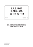
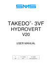
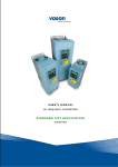
TAKEDO - 3VF HYDROVERT NXP USER MANUAL 01 11-11-2010 REV. DATE R.T. Check and Approval PAGE DELIBERATELY BLANK 2 TAKEDO - 3VF HYDROVERT NXP USER MANUAL Release 01 date 11-11-2010 ALPHABETICAL INDEX ACTIVE FAULTS OR ALARMS Page 15 Par. 5.3 IDENTIFICATION (AUTO-TUNING) Page 16 Par. 6.2 SAFETY INSTRUCTIONS Page 5 Par. 2.1 PRECAUTIONS Page 5 Par. 2.2 POWER CONNECTION Page 6 Par. 3 ELECTROMAGNETIC COMPATIBILITY (EMC) Page 7 Par. 3.2 FAN CONTROL Page 16 Par. 6.3 MAINTENANCE Page 21 Par. 7 MONITOR Page 11 Par. 5.1 PARAMETERS Page 12 Par. 5.2 ADJUSTMENTS Page 16 Par. 6.1÷7 EMERGENCY ADJUSTMENTS Page 20 Par. 6.17 DOWN RUN ADJUSTMENTS Page 19 Par. 6.13÷15 UP RUN ADJUSTMENTS Page 17 Par. 6.8÷11 MAXIMUM POWER ADJUSTMENTS Page 18 Par. 6.12 BRAKING RESISTOR Page 6 Par. 3.1 APPLICATION DIAGRAM Page 8 Par. 4 KEYPAD AND MENUS Page 9 Par. 5 INSTALLED POWER TABLE Page 4 TAKEDO - 3VF HYDROVERT NXP USER MANUAL Release 01 date 11-11-2010 3 HYDRAULIC LIFTS : INSTALLED POWER AND CURRENTS MOTOR POWER RATING PLATE ABSORBED CURRENT FROM MAINS (1) ABSORBED SOFT DIRECT STARTER STARTING STARTING HYDROVERT (A) INSTALLED POWER (4) INSTALLED POWER WITHOUT SPEED REDUCTION WITH SPEED REDUCTION DIRECT STARTING SOFT STARTER HYDROVERT POWER LIMIT set by HYDROVERT (kW) (kW) (kW) kW (A) SPEED REDUCTION AT FULL LOAD (ELECTRIC) RATED (kW) (2) (A) (A) (A) RATED ( ) STARTING 3 4.4 8 40 18 6.5 6.5 15 6 4.5 3 (4.8) -20 4 5 9 55 25 7.2 7.2 20 10 4.5 3 (4.8) -30 6 8 14.5 60 30 12 12 20 10 10 6 (9.6) -15 7.7 9.7 17.5 70 35 14 14 25 15 10 6 (9.6) -25 9.5 12 21.8 90 45 17.5 17.5 30 15 15 10 (16) -5 11 13.8 25 113 55 20 20 35 20 15 10 (16) -15 15 17.7 32 136 65 26 26 45 25 20 15 (24) -5 22 26 48 210 90 38 38 65 30 25 20 (32) -20 (MECHANICAL) (kW) 3 (%) NOTES: 1) Power supply voltage 400V. 2) Calculated considering cosφ at full load = 0.8. 3) With HYDROVERT cosφ = 0.98. 4) The INSTALLED POWER is the higher value of the 2 given by the following formulae: (a) P(kW) = √3 * V * Istart * cosφ (0.9) 2 (b) P(kW) = √3 * V * Irated * cosφ (0.9) 1 – INTRODUCTION HYDROVERT NXP is an inverter with special software for hydraulic systems, able to work both with old and new hydraulic power units. It controls the up run and, with prearranged hydraulic power units, also the down run. The advantages are: • • • • • • • No starting current peaks. The maximum starting current is the rated current. Power factor correction of absorbed current from mains. Cosϕ ϕ 0.98. Energy saving. Run comfort optimisation. Emergency rescue operation possible even upward. Adjustable inspection speed. Possibility of setting a maximum limit for the absorbed power from the mains, to limit the installed power. 2 – SAFETY INSTRUCTIONS AND PRECAUTIONS Read all of this manual before powering the equipment, following the step by step procedures. In particular, carefully read the Sections: ADJUSTMENT PROCEDURE and ACTIVE FAULTS. 2.1 SAFETY INSTRUCTIONS Carefully follow the procedures given below, to prevent the risk of serious accidents. 1- The leakage current from the inverter to earth is greater than 30mA, therefore a differential switch with Id of at least 300mA, type B or type A, must be provided. Regulations require the use of a cable with a section of at least 10 mm² for the earth connection. If the differential switch trips when the main power switch is closed, do not repeat the operation in succession, because the inverter could become permanently damaged. 2- If the parameters are incorrect, the inverter can cause the motor to rotate at a speed higher than synchronous speed. Do not run the motor beyond its electrical and mechanical limits. The installer is responsible for ensuring that movements occur in safe conditions, without exceeding the specified operating limits. 3- Risk of electrocution. Power the inverter only with the front cover fitted. NEVER remove the cover during operation. Before carrying out any operation on the equipment, disconnect the power supply and wait a few minutes for the internal capacitors to discharge. 4- The external braking resistor heats up during operation. Do not install it near or in contact with inflammable materials. To improve heat dissipation it is advisable to fix it to a metal plate. Make sure it is suitably protected and cannot be touched. 5- The inverter must always be connected to the mains. In case of an interruption, wait at least 1 minute before reconnecting. RECONNECTING WITHOUT WAITING LONG ENOUGH WILL DAMAGE THE INVERTER. 6- Do not use an oscilloscope or similar instruments to test the internal circuits of the inverter. This type of operation must be performed only by specialised personnel. 2.2 PRECAUTIONS Carefully follow the procedures given in the manual to avoid the risk of damaging the inverter. 1- Do not connect the equipment to a voltage higher than that permissible. An excessive voltage can cause permanent damage to the internal components. 2- To avoid damaging the inverter in case of prolonged stoppages with no power supply, before restarting proceed as follows: - If the inverter has been idle for several months, connect it to the power supply for at least 1 hour in order to regenerate the bus capacitors. - If the inverter has been idle for more than one year, power it for 1 hour at 50% lees than the nominal voltage, and then for 1 hour at nominal voltage. 3- Do not connect capacitors to the inverter outputs. 4- Before resetting an inverter fault, carefully check what caused activation of the protection. 5- Use an inverter with rated current equal to or higher than the motor rated current. 6- If necessary, the braking resistor must be connected between B+ and R-. If it is connected between B+ and B– the inverter will be damaged. 3 – POWER CIRCUIT CONNECTION L1;L2;L3 Mains power supply input U;V;W Inverter output B+;R- External braking resistor Earth Connect the mains power supply input phases in any order. Connect the three output phases to the contactors, then to the motor Connect the external braking resistor (if necessary) Connect to the building's earth system Example of power circuit connection 3.1 SAFETY INSTRUCTIONS 1- Do not power the inverter without first making the earth connection. 2- To increase inverter protection (especially against overvoltage due to electrical storms), three extrafastblow fuses (one for each phase) can be installed in series with the supply mains input terminals. The fuses must be rated according to the various sizes as given in the table below. The set of fuses, complete with protection box, can be supplied on request (not indispensable!). 3- To avoid permanently damaging the inverter, do not connect braking resistors with resistance or power ratings lower than those given in the TABLE 4- The inverter drive must be connected <<upstream>> of the power contactors. 5- The external braking resistor heats up during operation. Do not install it near or in contact with inflammable materials; protect it to prevent direct contact. 6- Wire earth connections and masses correctly (as indicated in par. 3.2) to avoid problems of EMC interference. 7- Pay particular attention to the power connection; if the input and output are inverted, the inverter will inevitably be damaged. RATED CURRENT (A) INVERTER NXP SERIES 400VOLT (380÷500V) BRAKING RESISTOR MINIMUM VALUE (Ω Ω) DIMENSIONS LxDxH (mm) 500Ω 1500W 42Ω 445x110x140 144x391x214 2x50Ω 1500W 14Ω 195x519x237 2x50Ω 1500W 21Ω 445x110x140 (*) 445x110x140 (*) NXP0045 195x519x237 2x50Ω 1500W 21Ω 445x110x140 (*) NXP0061 195x519x237 3x50Ω 1500W 14Ω 445x110x140 (*) NXP0072 NXP0087 NXP0105 NXP0140 NXP0168 237x591x257 237x591x257 237x591x257 291x758x344 291x758x344 5x50Ω 1500W 5x50Ω 1500W Ask SMS Ask SMS Ask SMS 6.1Ω 6.1Ω 445x110x140 (*) 445x110x140 (*) VACON CODE DIMENSIONS LxHxD (mm) SUPPLIED BY SMS 14 NXP0013 128x292x190 27 NXP0032 38 NXP0038 45 61 72 87 105 140 168 (*) The total size is that indicated multiplied by the number of resistors. TABLE – Fuses and braking resistors The braking resistor is necessary only if HYDROVERT is used to control the down run. 6 TAKEDO - 3VF HYDROVERT NXP USER MANUAL Release 01 date 11-11-2010 3.2 RULES FOR EMC COMPLIANT MOTOR - INVERTER WIRING For correct INVERTER – MOTOR assembly wiring, proceed as follows: 1- The inverter and motor must be connected directly to the building's earth system. 2- The power cables for the inverter/contactors and contactors/motor connection must be as short as possible, shielded four-core (three phases plus yellow/green earth wire), or four unshielded cables bound together and inserted in a raceway or a metal pipe connected to earth. In other words, there must be an earth wire as close as possible to the power wires in the same cable or in the same pipe. If shielded cable is used, continuity of the earth braid between the inverter/contactors and contactors/motor section must be ensured. It is advisable to connect the shielding to earth at both ends by means of a U-clip or with special terminals that can be supplied by SMS. SHEATH INSTALLATION PANEL SHIELD OMEGA CONNECTOR UNPAINTED AREA 3- 456- 7- 8- If the shield cannot be connected with a U clip inside the motor terminal block, it must be earthed on the frame before entering the block. It is also advisable (though not indispensable) to use shielded cable on the power input line, to avoid the possibility of radiated interference going outside the cable. The mains power input and inverter output cables must not be placed in the same raceway and should be kept as far apart as possible (at least 50 cm). The inverter power cables (input and output) and control cables must be kept as far apart as possible and must not run parallel, even if shielded; if the cables cross, they must be arranged at an angle of 90°. Irrespective of the connection to the building's earth system, the motor frame MUST be connected to the cable shield and to the yellow/green earth wire inside the shielded cable. The inverter emits radiated interference, which can therefore be picked up and carried outside the panel by the cables, especially by flexible cables which radiate the interference into the lift shaft. If this problem is to be avoided, the connections between the panel and the inverter must be made using shielded wires with shield connected to earth at both ends. Shielded cables must not be used without the shield connected to earth, as in this case any interference will be greater than with an unshielded cable. Any free or unused wires in a multicore cable must be connected to earth at both ends. Any cable, for control or external connections for the shaft and lift car, must never run near and parallel to the power cable, even if shielded; if parallel routing cannot be avoided, they must be in separate metal raceways. All earth connections must be as short and wide as possible. (a) (b) Solution (a) (copper braid) is preferable to solution (b) (wire). 9- To avoid unwanted tripping of the differential switch: • Make the power connection as short as possible • Use suitable differential switches (type A or B 300mA) • When possible, reduce the inverter carrier frequency: in fact, the lower the frequency the greater the motor noise, but with less current leakage to earth and less EMC interference; the motor windings are less stressed. TAKEDO - 3VF HYDROVERT NXP USER MANUAL Release 01 date 11-11-2010 7 8 S-UP SHIELDED CABLE TP D-DOWN EMERGENCY INSPECTION TP1 E-ENABLE V-SPEED (HIGH/LOW) 7 14 15 16 L1-N for 230V single-phase connection (0V) TAKEDO - 3VF HYDROVERT NXP USER MANUAL Release 01 date 11-11-2010 26 25 23 22 R- B+ W V U DO1 20 +24V(OUT) 12 RO2 RO1 HYDROVERT NXP 6 24Vdc 10 9 8 L3 L2 S T L1 R SHIELDED CABLE THREEPHASE LINE 400V M 3-PH – OPERATION Imax<400mA DC; Vmax<=125 Vdc DOWN VALVE CONTROL RELAY + OPERATION Imax< 400mA DC; Vmax<=125 Vdc UP VALVE AND CONTACTORS CONTROL RELAY (ONLY FOR DOWN RUN OPERATION) SPEED DETECTOR RELAY (for possible anticipated opening) Imax<50mA DC; V=24 Vdc SHIELDED CABLE SHIELDED CABLE EXTERNAL BRAKING RESISTOR EARTH CABLE TP1 CONTACTORS TP SHIELDED CABLE SHIELDED CABLE 4 – HYDROVERT NXP APPLICATION DIAGRAM 5 – KEYPAD AND MENUS The control panel has an alphanumeric display with nine status indicators and three lines of text for the menu, the descriptions of the menu/submenu and the number of the submenu or the value of the function displayed. There are also nine keys used for controlling the inverter, setting parameters and displaying values. The panel is removable, since all parts are isolated from the a.c. input voltage. The data on the panel is arranged in menus and submenus, necessary for displaying and processing control signals, displaying faults, measurements and for editing parameters. STATUS INDICATORS RUN = lights up when the motor is running = shows the selected rotation STOP = lights up when the motor is not running READY = lights up when the unit is powered and ready to use FAULT = lights up when a drive fault occurs ALARM = lights up when an alarm occurs Indication of position: displays the symbol and number of the menu, parameter, etc. The symbol I/O term indicates that the I/O terminals are the selected control interface; in other words, the commands are given via the I/O terminals. IMPORTANT: When used for lifts, the message Keypad or Bus/Comm must never appear in place of I/O term. Control panel with Liquid Crystal Display Description line: displays the description of the menu, value or fault. Values line: displays the numerical value and descriptor of reference data, parameters, etc. and the number of submenus available in each menu. Lights up when power is on. Indicates that the inverter is ready for use. Lights up when the drive is in operation. Lights up when risk conditions have arisen causing the drive to stop (Shutdown due to fault). At the same time, the FAULT indicator blinks on the display, which also shows a description of the fault; see Section 5.4 – Active Faults. Left Menu key Go back through menus. Move cursor to left (in the parameters menu). Exit edit mode. Hold down for 2…3 seconds to return to the main menu. Right Menu key Go forward through menus. Move cursor to right (in the parameters menu). Access edit mode. enter select Up arrow Scroll the main menu and pages of various submenus. Edit values, increasingly. Down arrow Scroll the main menu and pages of various submenus. Edit values, decreasingly. Reset key Use to reset active faults. Enter key Confirm selections Reset fault memory (2…3 seconds) Select key Use to shift between the last two indications displayed. Useful when wishing to see how the new changed value affects some other value. START key (NOT Used) START STOP key (NOT Used) STOP reset TAKEDO - 3VF HYDROVERT NXP USER MANUAL Release 01 date 11-11-2010 9 The submenus are accessible from the main menu using the key . The symbol M on the first text line indicates the main menu. It is followed by a number that refers to the submenu in question. The arrow (→ →) at the bottom right of the display indicates another submenu that can be displayed by pressing the key . To go back to the main menu from the submenu, just press the key . The data on the keypad is divided into Menus and Submenus. The main menus are arranged on six levels: M1-P2-F3-H4-S5-E6. To go from one menu to the next, press the keys or . M1=Visualizzazione / Monitor H4=Storico guasti / Fault history P2=Parametri / Parameters S5=Menù di sistema / System menu F3=Guasti attivi / Active faults E6=Schede espansione / Expansion boards Each menu contains submenus, which can also be on several levels. To access the submenus, press the key , then use the +/- keys to display the various quantities; to quit the submenu, press the key . KEY OF SYMBOLS CONTAINED IN MENUS AND SUBMENUS: M = menu (internal modes V,P,H,F) F = active fault V = read only H = fault history P = editable parameter 5.0 COPY OF PARAMETERS WITH KEYPAD The programming keypad can also be used to copy parameters from and to the inverter. This function is very handy when finding the optimum parameterisation for a system and other systems with the same characteristics must be prepared, but CAN ONLY BE USED TO COPY PARAMETERS BETWEEN INVERTERS WITH THE SAME APPLICATION SOFTWARE VERSION (the application software version is given on a label placed under the keypad). 5.0.1 - COPY FROM INVERTER TO KEYPAD Press the left arrow until ‘M’ followed by the menu number (e.g. M2) appears in the top left. Press the arrows at the top or bottom until M6 appears. Follows the indications on the display : S5 S5.3 S5.3.2 S5.3.2 S5.3.2 S5.3.2 System menu TransferParam To Panel To Panel To Panel To Panel S1>S11 → P1>P4 → Press the right arrow and S6.1 appears. Press the arrow at the top to S6.3. Press the right arrow and S6.3.1 appears. Press the arrow at the top to S6.3.2. Selection → Press the right arrow. All Param. Press enter and copying of parameters starts. Wait… Wait for copy to end. OK Copy ended . The keypad now contains the inverter data. 5.0.2 COPY FROM KEYPAD TO INVERTER The same method described above applies. By selecting S5.3.3 instead of S5.3.2 the display will show “From Panel” instead of “To Panel”, then proceed as above. Attention: Copy the data from keypad when the data contained in it has been drawn by an inverter of the same size as that in which the copy is being made. When connecting the keypad to the inverter on which the data is to be copied, the following will appear : Copy To Panel? enter/reset Press RESET to copy the contents of the keypad to the inverter. 10 Copy From Panel? enter/reset Press ENTER to start the copy procedure and wait. TAKEDO - 3VF HYDROVERT NXP USER MANUAL Release 01 date 11-11-2010 5.1 M1 = VISUALIZZAZIONE (MONITOR) CODE NAME OF SIGNAL CODE NAME OF SIGNAL V1.1 Frequenza uscita / Output frequency V1.11 DIN1, DIN2, DIN3 V1.2 Rif. Frequenza / Freq. Reference V1.12 DIN7, DIN8 V1.3 Velocità motore / Motor Speed V1.13 R01, R02, R03 V1.4 Corrente motore / Motor Current V1.14 Number of anticipated contactor openings at stop. V1.5 Coppia motore / Motor Torque V1.15 DIN4, DIN5, DIN6 V1.6 Potenza motore / Motor Power V1.16 DO1, AODig V1.7 Tensione motore / Motor Voltage V1.17 Motor Temperature in % (110% = Overtemperature Alarm) V1.8 Tensione bus C.C. / DC-link Voltage V1.18 Actual Power (kW) V1.9 Temperatura inverter / Unit temperature V1.19 Deceleration Distance V1.10 Analogue Output (20mA) Inputs 8 – 9 – 10 Up, Speed (High/Low), Enable Not Used Relay outputs Contactor Control, Down Valve Control, Not Used Inputs 14 – 15 – 16 Down, Emergency, Inspection Outputs 12-20 and 18-19 Speed detector, Fault TAKEDO - 3VF HYDROVERT NXP USER MANUAL Release 01 date 11-11-2010 11 5.2 P2 = PARAMETERS Index IMPORTANT Parameters with grey background can only be changed on advice of SMS! Descrizione Valore Description Unit Value P2.1 - PARAMETRI BASE / BASIC PARAMETERS P 2.1.1 Limite corrente 1,1 * In Inverter Current Limit 1.1 * In Inverter A P 2.1.2 TensioneNomMotor 400 Motor Nom Voltg 400 V P 2.1.3 FrequenNomMotore 50,00 Motor Nom Freq 50.00 Hz P 2.1.4 VelocitàNomMotor 2800 Motor Nom Speed 2800 rpm P 2.1.5 CorrenteNomMotor In Inverter Motor Nom Currnt In Inverter A P 2.1.6 Cos fi motore 0,80 Motor Cos Phi 0.80 P 2.1.7 Identificazione 0 Identification 0 P 2.1.8 Max Potenza 150 Max Power 150 P 2.1.9 Control Ventola 1 / Marcia Fan Control 1 / Run P 2.1.10 Sblocco Menù 0 Unlock Menu 0 % P2.2 – SALITA / UPWARD P 2.2.1 Rampa Pre Avviam 0,2 PreStart Ramp 0.20 s P 2.2.2 Freq PreAvviamen 2,00 PreStart Freq 2.00 Hz P 2.2.3 Tempo PreAvviam 1,0 PreStart Time 1.0 s P 2.2.4 Tempo Acceler 2,0 Accelerat Time 2.0 s P 2.2.5 Tempo Deceler 1,0 Decelerat Time 1.0 s P 2.2.6 Alta Velocità 50,00 High Speed 50.00 Hz P 2.2.7 Bassa Velocità 7,00 Low Speed 7.00 Hz P 2.2.8 Vel Rilivellamen 2,00 Levelling Speed 2.00 Hz P 2.2.9 Vel Manutenzione 25,00 Maintenance Speed 25.00 Hz P 2.2.10 Tempo Incr Accel 2,00 Accel Inc Time 2.00 s P 2.2.11 Tempo Decr Accel 0,20 Accel Dec Time 0.20 s P 2.2.12 Tempo Incr Decel 0,20 Decel Inc Time 0.20 s P 2.2.13 Tempo Decr Decel 1,00 Decel Dec Time 1.00 s P 2.2.14 Tempo Dec Final 1,5 Final Decel Time 1.5 s P 2.2.15 CoeffDecLim Pote 120 PowLimDecFactor 120 % P 2.2.16 Compens Perdite 0 Losses Compensat 0 rpm P 2.2.17 CorrenteNoCarico 0,7 * In Inverter NoLoadCurrent 0.7 * In Inverter A P 2.2.18 CorrentMaxCarico In Inverter MaxloadCurrent In Inverter A P 2.2.19 Compens Carico 2,00 Load Compens 2.00 Hz P 2.2.20 Comp Temp Olio 1,00 Oil Temp Compens 1.00 Hz P 2.2.21 Livel 1a Rampa 2,00 Level 1st Ramp 2.00 s P 2.2.22 Misura Pot % 80,00 Power Meas % 80.00 % P 2.2.23 Misura Pot Hz 60,00 Power Meas Hz 60.00 Hz P 2.2.24 IncrCorrMisPot 30,0 PowMcCurrentIncr 30.0 % P 2.2.25 SogliaMinCarico 35,00 MinLoadThresh 35,00 % P2.3 - DISCESA / DOWNWARD P 2.3.1 Rampa Pre Avviam 2,0 PreStart Ramp 2.0 s P 2.3.2 Freq PreAvviamen 2,00 PreStart Freq 2.00 Hz P 2.3.3 Tempo PreAvviam 1,0 PreStart Time 1.0 s P 2.3.4 Tempo Acceler 2,0 Accelerat Time 2.0 s P 2.3.5 Tempo Deceler 1,0 Decelerat Time 1.0 s P 2.3.6 Alta Velocità 50,00 High Speed 50.00 Hz P 2.3.7 Bassa Velocità 7,00 Low Speed 7.00 Hz P 2.3.8 Vel Rilivellamen 2,00 Levelling Speed 2.00 Hz P 2.3.9 Vel Manutenzione 25,00 Maintenance Speed 25.00 Hz P 2.3.10 Tempo Incr Accel 2,00 Accel Inc Time 2.00 s P 2.3.11 Tempo Decr Accel 0,20 Accel Dec Time 0.20 s P 2.3.12 Tempo Incr Decel 0,20 Decel Inc Time 0.20 s P 2.3.13 Tempo Decr Decel 1,00 Decel Dec Time 1.00 s 12 TAKEDO - 3VF HYDROVERT NXP USER MANUAL Release 01 date 11-11-2010 P 2.3.14 Tempo Dec Final Index 1,0 Descrizione Final Decel Time Valore 1.0 Description s Unit Value CONT. P2.3 - DISCESA / DOWNWARD P 2.3.15 Arrot Finale 1 0,00 Final Round 1 0.00 s P 2.3.16 Arrot Finale 2 0,00 Final Round 2 0.00 s P 2.3.17 Frequenza Finale 2,00 Final Frequency 2.00 Hz P 2.3.18 Tempo Finale 2,0 Final Time 2.0 s P 2.3.19 Rampa Finale 1,0 Final Ramp 1.0 s P 2.3.20 Minima Frequenza 1,00 Min Low Freq 1.00 Hz P 2.3.21 Compens Perdite 0 Losses Compensat 0 rpm P 2.3.22 Soglia MinCarico 50,0 Min Load Thresh 50.0 % P 2.3.23 CorrenteNoCarico 0,7 * In Inverter NoLoadCurrent 0.7 * In Inverter A P 2.3.24 CorrentMaxCarico In Inverter MaxLoadCurrent In Inverter A P 2.3.25 Compens Carico 2,00 Load Compens 2.00 Hz P 2.3.26 Comp Temp Olio 1,00 Oil Temp Compens 1.00 Hz P 2.3.27 FattoreScorrim 50,0 MotorSlipFactor 50.0 % P 2.3.28 CompBassaVeloc -3 LowSpeedComp -3 Hz P2.4 - CONTROLLO VALVOLA / VALVE CONTROL P 2.4.1 MinCorrenteValv 0,0 Valve Min Curr 0.0 % P 2.4.2 RitardoAperValv 2,00 Valve OpenDelay 2.00 s P 2.4.3 RitardoChiusValv 3,00 Valve CloseDelay 3.00 s P2.5 - CONTROLLO AZIONAMENTO / DRIVE CONTROL P 2.5.1 ChopperFrenatura 1 / Attivo Brake Chopper 1 / Active P 2.5.2 ModoContMotSali 1 / OL Contr vel MotorContrModeUp 1 / OL SpeedCont P 2.5.3 FreqCommutazione 6,0 Switching Freq 6.0 P 2.5.4 ControlSottotens 1 / Attivo Undervolt Contr 1 / On P 2.5.5 Ottimizzaz V/f 1 / "Boost"autom U/f Optimisation 1 / AutoTorqBoos P 2.5.6 PntoIndebolCampo 50,00 Field WeakngPnt 50.00 Hz P 2.5.7 Tensione al PIC 100,00 Voltage at FWP 100.00 % P 2.5.8 V/fFreqIntermdia 2,00 U/f Mid Freq 2.00 Hz P 2.5.9 V/fTensIntermdia 6,00 U/f Mid Voltg 6.00 % P 2.5.10 Tensione a Freq0 4,00 Zero Freq Voltg 4.00 % P 2.5.11 Riservato 0 Reserved 0 P 2.5.12 Bassa Freq Switc 5,0 Low Switch Freq 5.0 kHz P 2.5.13 Soglia BasFreSwi 5,00 LSF Threshold 5.00 Hz P 2.5.14 Caduta RS Misura 0 Ident RS VltDrop 0 P 2.5.15 Corrente a 0Hz 80 Current at 0 Hz 80 P 2.5.16 Reg Veloc Kp 3000 Speed Control Kp 3000 P 2.5.17 Reg Veloc Ki 300 Speed Control Ki 300 P 2.5.18 GuadStabCoppia 300 TorqStabilGain 300 P 2.5.19 GuadStabTens 100 VoltStabilGain 100 P 2.5.20 ModoContMotDisc 1 / OL Contr vel MotorContrModeDn 1 / OL SpeedCont kHz % P2.6 - EMERGENZA / EVACUATION P 2.6.1 Vel EmergSalita 5,00 Evac Speed Up 5.00 Hz P 2.6.2 Vel EmergDiscesa 10,00 Evac Speed Down 10.00 Hz P 2.6.3 Modo 1 / Automatico Mode 1 / Automatic P 2.6.4 FreqCommutazione 3,0 Switching Freq 3.0 kHz P2.7 - RISERVATO / RESERVED P2.8 – SEGNALI INGRESSO / INPUT SIGNALS P 2.8.1 Sel Salita mors.8 1 / DIN1 Sel Start FWD term.8 1 / DIN1 P 2.8.2 Sel Discesa mors.14 4 / DIN4 Sel Start REV term.14 4 / DIN4 P 2.8.3 Sel Vel Alta mors.9 2 / DIN2 Sel High Speed term.9 2 / DIN2 P 2.8.4 Sel Ispezione mors.16 6 / DIN6 Sel Maintenance term.16 6 / DIN6 P 2.8.5 Sel Abilitazione mors.10 3 / DIN3 Sel Enable term.10 3 / DIN3 TAKEDO - 3VF HYDROVERT NXP USER MANUAL Release 01 date 11-11-2010 13 P 2.8.6 Index Sel Emergenza mors.15 5 / DIN5 Descrizione Sel Emergency Valore term.15 5 / DIN5 Description Unit Value P2.9 – SEGNALI USCITA / OUTPUT SIGNALS P 2.9.1 Funzione RO1 mors.22-23 3 / Contattore RO1 Function P 2.9.2 FunzDigAO AODigitalFunct term.18-19 1 / Ready P 2.9.3 Funzione RO2 mors.25-26 2 / ContrValvola RO2 Function P 2.9.4 Funzione RO3 Non Usato RO3 Function P 2.9.5 Funz DO 4 / SupervFreq DO P 2.9.6 Funzione AO1 0 / FunzDigitale AO1 Function 0 / DigitalFunct P 2.9.7 Filtro AO1 0,00 AO1 Filter Time 0.00 P 2.9.8 Minimo AO1 0 / 0 mA AO1 Minimum 0 / 0 mA P 2.9.9 Scalat AO1 100 AO1 Scale 100 P 2.9.10 Lim1SupervisFreq 1 / Limite infer Freq Supv Lim 1 1 / Low Limit P 2.9.11 Soglia1SuprvFreq 30,00 Freq Supv Val 1 30.00 mors.18-19 mors.20 1 / Pronto term.22-23 term.25-26 3 / Contactor 2 / Valve Cntrl Not Used term.20 4 / FreqSuperv s % Hz P2.10 – PROTEZIONI / PROTECTIONS P 2.10.1 SquilibrFasiUsc 2 / Guasto OutputPh. Superv 2 / Fault P 2.10.2 ReazionSottotens 2 / Guasto UVolt Fault Resp 2 / Fault P 2.10.3 Guasto a terra 2 / Guasto Earth fault 2 / Fault P 2.10.4 Protez di Stallo 2 / Guasto Stall Protection 2 / Fault P 2.10.5 Corrente Stallo 110,0 Stall Current 110.0 % P 2.10.6 Lim Tempo Stallo 3,00 Stall Time Lim 3.00 s P 2.10.7 Lim Freq Stallo 6,00 Stall Freq Lim 6.00 Hz P 2.10.8 SensoreTempPoten 0 / Legge PwrUnitTempSense 0 / Read P 2.10.9 Max Sovraveloc 110,0 Max Overspeed 110.0 P 2.10.10 ApertAnticContat 20 AdvancContFault 20 P 2.10.11 TimeOut Abilitaz 3,0 EnableOn TimeOut 3.0 P 2.10.12 VerifCadutaAbili 1 / Sì Enable Off Check 1 / Yes P 2.10.13 Costante Termica 45 Thermal Constant 45 min P 2.10.14 Raffred a 0Hz 40,0 Cooling at 0Hz 40.0 % P 2.10.15 TVerifCoppiaDisc 3,0 DWTorqueChekTime 3.0 s P 2.10.16 SogliaVerCoppDisc 0 DwTorqueChekLevel 0 % % s P2.11 – RIAVVIO AUTOMATICO / AUTO RESTART P 2.11.1 RiavvioAutomatic 1 / Abilitato Autom. Restart 1 / Enabled P 2.11.2 Funzione Riavvio 0 / Rampa Restart Function 0 / Ramping P 2.11.3 Tempo di tentat 60,00 Trial Time 60.00 s P 2.11.4 Tempo di attesa 3,00 Wait Time 3.00 s P2.12 – TEMPERATURA / TEMPERATURE P2.12.1 Drive TempMin 10 Drive TempMin 10 °C P2.12.2 Drive TempMax 60 Drive TempMax 60 °C P2.12.3 Motore TempMax 80 Motor TempMax 80 °C 0 / No P2.13 – TEST PARACADUTE / PARACHUTE TEST P 2.13.1 Test Attivo 0 / No Test Active P 2.13.2 Sovravelocità 150,0 Test Overspeed 150.0 % P 2.13.3 Tempo Acceler 2,0 Accelerat Time 2.0 s P 2.13.4 TimeOut MaxVeloc 2,0 MaxSpeed TimeOut 2.0 s P 2.13.5 Tempo Deceler 1,5 Decelerat Time 1.5 s P 2.13.6 FreqChiusValvola 5,00 ValveCloseFreq 5.00 Hz 0 / Nessuna Sel ShortFloorSp 0 / None P2.14 – INTERPIANO / SHORT FLOOR P 2.14.1 Sel VelocInterp P 2.14.2 VelocSalitInterp 20,0 SF Speed UP 20.0 Hz P 2.14.3 VelocDisc Interp 20,0 SF Speed DW 20.0 Hz Licence Key 0 P2.15 – CODICE LICENZA / LICENCE KEY P 2.15.1 14 Codice Licenza 0 TAKEDO - 3VF HYDROVERT NXP USER MANUAL Release 01 date 11-11-2010 5.3 F3 = ACTIVE FAULTS Listed below are the most common fault messages. Do not to reset the alarm or fault without first checking what caused activation of the protection. Always deselect the run command before resetting a fault. 1 Overcurrent: The inverter has detected excessively high current. 2 62 Overvoltage: The DC voltage of the intermediate circuit has exceeded the specified limits. Earth fault: The current measurement system has detected that the sum of motor phase currents is not equal to 0, therefore possible current to earth. Charge contact: The charge contact is open when the START command is active. System fault: Component fault. Faulty operation. Braking resistor not connected. Undervoltage: The DC voltage of the intermediate circuit is below the specified limits. Output phases: No current on one or more output phases. The test is performed 3 times, the FAULT occurs the 4th time Inverter undertemperature: The heat sink temperature is below –10°C. Inverter overtemperature: The heat sink temperature is above 90°C. Motor stall: The motor stall protection has tripped. Motor overtemperature: The inverter motor temperature module has detected overheating of the motor. Probable motor overtemperature. Motor underload: The motor underload protection has tripped. Checksum error: Failed parameter retrieval from EEPROM. Faulty component. Counter fault: The value displayed by the counters is incorrect. Watchdog fault: Microprocessor fault. Start inhibit: Starting of the drive has been inhibited. Thermistor. (NOT USED) Internal bus communication. Removal of device: The optional circuit board or power unit has been removed Device not recognised: Optional circuit board or power unit not recognised. IGBT temperature: The IGBT overtemperature protection device has detected excessively high shortterm overload current (the motor on load does not start). Modification of device: The optional circuit board has been changed. Addition of device. The optional circuit board has been added. The current at the analogue input is < 4mA. Panel communication fault: Interrupted connection between control panel and inverter. Field bus fault: The data connection between field bus Master and field bus board is interrupted Anticipated stop with respect to low speed: The car reaches the floor when still decelerating Low current. Enable lost during run. 63 Output phases: No current in one or more output phases. 64 Low reference. Time out enable: The enable command is still ON 3 seconds after contactor control switch-off. 3 5 8 9 11 13 14 15 16 17 22 24 25 26 29 34 39 40 41 44 45 50 52 53 60 61 65 67 *68 69 70 71 76 Overspeed: Due to a fault the inverter exceeds the maximum frequency. Anticipated contactor opening: (See Alarm 68 NOTE) The contactors between inverter and motor opened before inverter switch-off. No Enable: Indicates that the contactors closed signal (input 10) was not activated within 2 sec. of the contactor command (output terminals 22-23). Wrong licence key: The correct licence key was not entered in parameter P2.15.1 as a result of an application software upgrade by the client. No identification: The procedure indicated in par. 6.2 was unsuccessful. Check the connection between inverter and motor. Down valve not open: The valve closed during the down run. Check valve operation and its electrical connections. TAKEDO - 3VF HYDROVERT NXP USER MANUAL Release 01 date 11-11-2010 15 *NOTE Alarm 68 After 20 activations of this alarm, the system goes out of service and it is necessary to press the RESET key to restore operation. Eliminate the problem by delaying contactor opening. If the problem persists, contact SMS. CONTINUOUS ACTIVATION OF ALARM 68 CAN CAUSE INVERTER BREAKAGE. 5.4 H4 = FAULT MEMORY The inverter memory can store up to 10 faults in the order in which they occur. The last fault is designated H4.1, the second last H4.2 etc. If the memory contains 10 faults that have not been erased, the next fault to occur will replace the oldest fault present in the memory. To reset faults, press the (ENTER) key enter for at least 3 seconds. 5.5 S5 = SYSTEM MENU The message S1→S11 appears under the menu name. This indicates that there are 11 submenus. S5.1 Language Setting: ITALIAN / ENGLISH / FRENCH . S5.2 Application Setting: SMS Hydrov SMS advises against modifying other parameters relevant to this MENU. 5.6 E6 = EXPANSION BOARDS (Monitor I/O board OPTA2) V 6.1.1.1 DigOUT:B.1 (Output RO1 status) V 6.1.1.2 DigOUT:B.2 (Output RO2 status) 6 – ADJUSTMENT PROCEDURE Before any adjustment or modification of parameters, proceed as follows: 6.1 – Set the motor rating in parameters P2.1.2/3/4/5/6 6.2 – Carry out motor identification (or auto-tuning) through parameter P2.1.7 After entering the correct motor values, it is essential to do the IDENTIFICATION routine: - Set parameter 2.1.7 to 1 and carry out a call command. The contactors energise, the motor does not start, and the message "RUN" appears on the keypad. - When the message “STOP” appears, deactivate the call (e.g. opening the operation valve). - The low speed boost parameters are now optimised. If any motor value is modified, the IDENTIFICATION routine must be repeated 6.3 – FAN CONTROL Set parameter P2.1.9 (fan control) as required: 0 = continuous operation 1 = run - works during run and for another minute after the stop. 2 = temperature - works only if the inverter reaches a temperature of 45°C. 3 = speed contr. - works during run and for another minute after the stop, at 3 speed levels depending on the heat sink temperature (< 40°C, between 40 and 50°C, > 50°C) 6.4 – Set the required value for the nominal speed P2.2.6 (P2.3.6 for down run). 6.5 – Set the required value for the inspection speed P2.2.9 (P2.3.9 for down run). 6.6 – Set the required value for the low speed P2.2.7 (P2.3.7 for down run). 6.7 – Set the motor current values for up run with car empty (P2.2.17) and fully loaded (P2.2.18) – if necessary, also the corresponding values P2.3.23 and P2.3.24 for down run – proceeding as follows: - display the motor current on the MONITOR menu (V1.4) with car empty, command an up run, read the current value and set it in P2.2.17. if necessary, do the same operation in down run, read the current value and set it in P2.3.23. carry out the same operation with car fully loaded in up run (down run) and set the read values in P2.2.18 (P2.3.24). IMPORTANT: 16 When reading the current absorbed at full load, check the Absorbed Power value in V1.18: THIS is the ABSORBED power measured by the electricity company; the motor rating plate gives the motor OUTPUT. TAKEDO - 3VF HYDROVERT NXP USER MANUAL Release 01 date 11-11-2010 6.8 – UP RUN adjustments CAR SPEED CURVE P2.2.10 P2.2.2 P2.2.11 P2.2.4 2.2.12 P2.2.5 P2.2.13 P2.2.6 P2.2.9 (INSPECTION) RE-LEVELLING P2.2.2 P2.2.14 P2.2.1 P2.2.8 P2.2.1 P2.2.7 UP RUN COMMAND (8) HIGH SPEED (9) OR INSPECTION (4) COMMAND ENABLE COMMAND (10) P2.2.3 P2.2.3 PRE-STARTING MOTOR CONTACTORS AND HIGH SPEED UP VALVE RELAY (22-23) 0.3’’ EMERGENCY COMMAND (2) Exact command sequence Up run: 1- Entering of UP command (8), output R01(22-23) is energised. When the contactors are closed, the ENABLE input (10) must be activated: in this way motor start is enabled. If the HIGH or INSPECTION speed level is enabled, the motor goes to "high" or "inspection" speed (P2.2.6 or P2.2.9). If no speed level is enabled (e.g. during re-levelling at floor) the motor will run at rerevelling speed (P2.2.8). 2- During the normal run, the HIGH SPEED signal (9) must be deactivated for a deceleration command: in this way, the inverter automatically goes to “low” speed (P2.2.7). 3- On reaching the floor, the UP command (8) must open, the inverter slows down the motor until it stops, deactivating the contactor command R01(22-23). As a result, the ENABLE command (10) is deactivated. 6.9 – Adjusting UP STARTING In order to obtain good starting controlled by the inverter, it is advisable to operate on the hydraulic valve, adjusting the maximum opening, like for having an immediate and quick start without inverter (“open the valve fully”). To obtain "smooth" starts without jerking, the car must move a little before acceleration starts. This is obtained with parameters P2.2.1, P2.2.2, P2.2.3 suitably adjusted. Then adjust acceleration with parameters P2.2.4 and P2.2.10. PARAMETER THE CAR STARTS WITH A JERK THE CAR STARTS WITH A DELAY P2.2.2 ↑ ↑ THE CAR ACCELERATES TOO QUICKLY = P2.2.3 P2.2.4 ↑ = ↑ = ↑ P2.2.10 ↑ = ↑ Key: = ↑ increase the parameter value ↓ decrease the parameter value = the parameter does not affect the adjustment TAKEDO - 3VF HYDROVERT NXP USER MANUAL Release 01 date 11-11-2010 17 6.10 – Adjusting UP STOP When the HIGH SPEED command is deactivated and the UP command stays on, the slow-down stage starts; when the car reaches the floor, the UP command is deactivated and the motor automatically goes to zero speed. To obtain the required stopping precision, adjust parameters P2.2.7 (Low Speed) and P2.2.14 (Final Deceleration). THE CAR STOPS BEFORE THE FLOOR AFTER THE LOW SPEED RUN THE CAR REACHES THE FLOOR AFTER A TOO LONG LOW SPEED RUN THE CAR REACHES THE FLOOR WITHOUT ANY LOW SPEED RUN THE CAR GOES PAST THE FLOOR AFTER THE LOW SPEED RUN P2.2.7 ↑ = ↓ = ↓ ↑ P2.2.14 = = ↓ ↑ PARAMETER P2.2.5 = Stopping precision depends on the car load (weight to be lifted) and the oil temperature. To make stopping precise in any conditions, proceed as follows: - Adjust the stop with oil cold and car empty, by means of parameters P2.2.7 and P2.2.14. - Test stopping at floor level with car fully loaded: the car normally stops a little before the floor level. Increase parameter P2.2.19 until obtaining the required precision. - Do numerous runs to heat up the oil then test stopping precision when the oil is hot. If the car stops before the floor level, increase parameter P2.2.20 until obtaining the required precision. - Lastly, with oil cold and car empty, check that the stopping precision is still the same as that obtained with the initial tests. 6.11 – Adjusting RE-LEVELLING Test re-levelling with the car empty and loaded, adjusting parameter P2.2.8 until obtaining the required stopping. 6.12 – Adjusting MAXIMUM ABSORBED POWER When having to limit absorbed power, to reduce the installed power and therefore energy costs, proceed as follows: - Set in P2.1.8 the required percentage of maximum power absorption. Example: A motor of 10kW power (rating), V=400V, Frequency=50Hz, I=22A, cos phi=0.8 Current measured in up run at full load = 25A Power value read in V1.18 = 14kW To limit the max. absorbed power to 10kW, set 70% in P2.1.8, because 10kW is 70% of 14kW. - Set in P2.2.23 the frequency value for the power check (the default value is 60Hz, therefore it is never enabled). A value of between 20 and 25Hz is usual. After the measurement, the motor will not exceed the speed limit, which remains within the set maximum power. - Then do a test with load, checking that the value displayed in V1.18 is the required value (10kW in the example). - If the read value is higher or lower, decrease or increase P2.1.8 until obtaining the required value. Power limitation occurs by reducing the car speed, however, stopping at the floor and the run at low speed must be the same as with empty car (when power limitation is not active): If the low speed run is longer, increase P2.2.15, and if the low speed run is shorter decease P2.2.15, until obtaining the required condition. 18 TAKEDO - 3VF HYDROVERT NXP USER MANUAL Release 01 date 11-11-2010 6.13 – RUN DOWN adjustments (only with special hydraulic power unit) CAR SPEED CURVE P2.3.11 P2.3.10 P2.3.5 P2.3.13 2.3.12 P2.3.4 RE-LEVELLING P2.3.8 P2.3.2 P2.3.14 P2.3.6 P2.3.1 P2.3.7 DOWN RUN COMMAND (14) HIGH SPEED (9) OR INSPECTION (16) ENABLE COMMAND (10) MOTOR CONTACTORS RELAY (22-23) 0.3’’ DOWN VALVE COMMAND (25-26) 6.14 – Adjusting DOWN STARTING To obtain "smooth" starts without jerking, the car must move a little before acceleration starts. This is obtained with parameters: PARAMETER THE CAR MOVES UP FIRST, THEN DOWN THE CAR STARTS DOWN WITH A JERK P2.3.2 ↓ ↑ THE CAR ACCELERATES TOO QUICKLY = P2.3.3 P2.3.4 ↓ = ↑ = ↑ P2.3.9 = = ↑ = Key: ↑ increase the parameter value ↓ decrease the parameter value = the parameter does not affect the adjustment 6.15 – Adjusting DOWN STOP To obtain a precise and "smooth" stop, with minimal variations in load conditions, it is necessary to adjust some parameters: THE CAR REACHES THE FLOOR WHEN STILL DECELERATING (NOT AT A STEADY SPEED) THE CAR REACHES THE FLOOR AFTER A TOO LONG LOW SPEED RUN P2.3.7 ↓ = ↑ = P2.3.13 = = P2.3.16 = P2.3.17 P2.4.3 PARAMETER P2.3.5 THE CAR STOPS AFTER THE FLOOR THE CAR STOPS BEFORE THE FLOOR THE CAR STOPS SUDDENLY THE CAR STOPS UP WITH A JERK = = = = ↓ ↑ = = ↓ = ↑ = = = = ↑ ↓ = = = = ↑ ↓ = = = = ↑ ↓ ALWAYS CHANGE THE PARAMETERS ONE AT A TIME. To obtain a correct stop, with car empty and loaded, with oil cold or hot, adjust parameters P2.3.25 and P2.3.26 in the same way as for the up stop adjustment. TAKEDO - 3VF HYDROVERT NXP USER MANUAL Release 01 date 11-11-2010 19 6.16 – General rules for correct adjustment - If the car speed is not steady at high speed, check the motor data. In particular, the motor data must match the "real" data. Also make sure the mechanical part (car/piston) has even friction along the run. - To obtain a stop with constant precision, the car must travel a short distance (5÷10cm) at a steady low speed (adjust the parameters as indicated in the table). - Adjust the low speed to the required value, bearing in mind that too low a value increases the time taken to reach the floor. - Do not adjust the switching frequency to values that are too high, otherwise unnecessary motor and inverter overheating will occur. 6.17 – EMERGENCY operation parameters (Input DIN5 – Terminal 15) Operation on batteries is used only when the motor works in up run and down run. If the EMERGENCY MODE (P2.6.3) is AUTOMATIC, car movement is always controlled in down run; if MANUAL, movement can be controlled in the required direction (up or down). The battery power supply must be at least 96Vdc P2.6.1 Up emergency speed P2.6.2 Down emergency speed P2.6.3 Emergency mode MANUAL must be set (P2.6.3=0) to go up; in AUTOMATIC (P2.6.3=1) it starts in any case in down direction) P2.6.4 Switching frequency (3 kHz is sufficient) P2.6.5 Motor control mode - Open loop (P2.6.5=1) 6.18 – ALARMS THAT CAN APPEAR DURING SYSTEM COMMISSIONING 60 = Anticipated stop: the system arrives at the floor before low speed has been reached, i.e. when still decelerating; in this case, reduce the deceleration time 2.2.5 (2.3.5 in DOWN RUN). 2 = Overvoltage: the internal bus has reached too high values. Make sure the braking resistor is connected and has the resistance value according to the table. Increase the deceleration distance if necessary. 61= Low current: The valve fails to open because the motor current is too low (change 2.4.1=minimum valve opening current) 63= Output phases: The inverter has detected the lack of current in one or more output phases. 68= 20 ANTICIPATED CONTACTOR OPENING: The contactors between inverter and motor opened BEFORE inverter switch-off. Repeated activation of this alarm causes inverter breakage and early wear of the contactors. TAKEDO - 3VF HYDROVERT NXP USER MANUAL Release 01 date 11-11-2010 7 – CHECKS AND MAINTENANCE To ensure long service life and optimum operation of the inverter, carry out the following checks at regular intervals. Operate on the inverter only after disconnecting the power and making sure the keypad is off. 1- Remove the dust collected on the cooling fins and control circuit board, if possible by blowing with compressed air or using a vacuum cleaner. 2- Make sure no screws are loose in the power or control terminal blocks. 3- Make sure inverter operation is <<normal>> and that there are no signs of anomalous overheating. 7.1 MEGGER TEST When doing insulation tests using a Megger tester on the input/output cables or on the motor, remove all the connections from all the inverter terminals and perform the test only on the power circuit, according to the diagram opposite. Do not test the control circuits. DC 500V MEGGER DC L1 U INVERTER L2 V L3 W For further details and suggestions, contact: SMS SISTEMI e MICROSISTEMI s.r.l. (SASSI HOLDING Group) Share Capital 260,000 fully paid-up Via Guido Rossa, 46/48/50 40056 Crespellano BO Admin. Econ. Reg. 272354 Tax File no. - Trade Reg. Bo 03190050371 VAT Reg. no. IT 00601981202 Tel. : +39 051 969037 Fax : +39 051 969303 Tel. Technical Service: +39 051 6720710 Website: www.sms.bo.it E-mail : [email protected] TAKEDO - 3VF HYDROVERT NXP USER MANUAL Release 01 date 11-11-2010 21 22 TAKEDO - 3VF HYDROVERT NXP USER MANUAL Release 01 date 11-11-2010