1
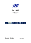
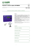
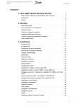
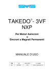
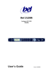
TAKEDO - 3VF NXL INSTRUCTION MANUAL 5 16-01-2007 REL. DATE T.M. Check and Approval INDEX 2 1 INTRODUCTION..................................................................................Page 3 2 SAFETY WARNINGS AND CAUTIONS ..............................................Page 3 3 CONNECTING THE POWER CIRCUIT...............................................Page 4 4 BASIC CONFIGURATION APPLICATION EXAMPLE.........................Page 6 5 KEYPAD AND PROGRAMMING ........................................................Page 7 5.1 MONITOR ............................................................................................. Page 7 5.2 PARAMETERS...................................................................................... Page 8 5.3 FAULTS ................................................................................................ Page 9 6 ADJUSTMENT PROCEDURE .............................................................Page 10 7 CHECKS AND MAINTENANCE...........................................................Page 13 8 SUMMARY TABLES OF SASSI MOTOR PARAMETERS...................Page 12 DECLARATION OF CONFORMITY.....................................................Page 14 TAKEDO - 3VF NXL USER MANUAL Release 5 date 16-01-2007 1 – INTRODUCTION TAKEDO-3VF NXL is an inverter drive with built-in EMC filter and smoothing choke, responding to European Directives 89/336/EEC (electromagnetic compatibility) and 73/23/EEC (low voltage equipment). The inverter can operate only in open loop conditions. This manual provides you with the necessary information about putting on duty and the operation of NXL frequency converter. You can found further information about application and installation in a lift control panel in the ANNEX NXL FOR PANEL WIRING SPECIALISTS, available in electronic edition on our website: www.sms.bo.it. 2 – SAFETY WARNINGS AND CAUTIONS Read this manual in its entirety before powering up the equipment, following the procedures step by step. In detail, please read carefully the Chapters: 6 – ADJUSTMENT PROCEDURE 5.3 – ACTIVE FAULTS 2.1 SAFETY WARNINGS Follow the procedures indicated below with care, to avoid any risk of serious accidents. 1- Do not use an oscilloscope or other such instrument to test the internal circuits of the inverter. This type of operation must be performed only by a specialist technician. 2- The leakage current from the inverter to earth is greater than 30mA, and accordingly, the power circuit must incorporate a residual current device with Id no less than 300mA, type B or type A. Regulations require that the connection to earth be made with cable of not less than 10 mm² section. If the residual current device should trip closing the main power switch, do not perform this operation repeatedly because this could lead to permanent damage to the inverter drive. Check that the residual current device is rated at least 300mA. 3- If the parameters used in programming the drive are incorrect, the motor may rotate at a speed higher than synchronous. Do not run the motor beyond its specified electrical and mechanical limits. The installer is responsible for ensuring that movements are generated in conditions of safety, without exceeding specified operating limits. 4- Risk of electrocution. Power up the inverter only with the front cover fitted. NEVER remove the cover during operation. Before carrying out any operation on the equipment, isolate from the electrical power supply and wait a few minutes for the internal capacitors to discharge. 5- The external braking resistor heats up during operation. Do not install it close to or in contact with inflammable materials. To improve heat dissipation it is good practice to fix the resistor to a metal plate. Ensure it is properly protected and cannot be touched. 6- The inverter must be constantly supplied with mains power. In the event of an interruption in the mains power supply, wait at least 1 minute before reconnecting. EXCESSIVELY RAPID RECONNECTION TO THE POWER SUPPLY CAN DAMAGE THE INVERTER. 2.2 CAUTIONS Follow the procedures indicated in the manual with care, to avoid risk of damaging or destroying the drive. 1- Do not connect the equipment to a voltage higher than the permissible input voltage. Excessive voltage can cause irreparable damage to internal components. 2- To avoid damaging the inverter in the event of prolonged stoppages with no power supply, before restarting the drive proceed as follows: - If the inverter has been idle for several months, connect it to the power supply for at least 1 hour in such a way as to recharge the bus capacitors. - If the inverter has been idle for more than one year, supply it for 1 hour with a level of voltage 50% lower than the nominal input voltage, and then supply it with the nominal input voltage for 1 hour. 3- Do not connect capacitors to the inverter outputs. 4- If any drive protection function trips, before resetting the fault establish beyond doubt what has caused the protection circuit to trip. 5- It is advisable to balance the system at 50%. If balanced at 40%, the UP current under full load will be greater, and it could become necessary to select a drive with a higher specification than would normally be sufficient. 6- Use an inverter having rated current equal to or greater than the rated current of the motor. 7- The braking resistor must be connected between B+ and R-. If the resistor is connected between B+ and B– the inverter may be damaged. TAKEDO - 3VF NXL USER MANUAL Release 5 date 16-01-2007 3 3 – CONNECTING THE POWER CIRCUIT L1;L2;L3 A.C. power input U;V;W Inverter output B+;R- External braking resistor Earth Connect the three phases of the power supply to this three terminals, in any order. Connect the three output phases to the contactors, then to the motor Connect the external braking resistor Connect to the building earth system Example of connection of the power circuit 3.1 SAFETY WARNINGS 1- Do not power up the inverter without first making the connection to earth. 2- To increase the inverter protection (especially against overvoltage resulting from electrical storms) three fast-acting fuses (one for each phase) can be installed in series with the A.C. power input terminals. The fuses must be rated in accordance with the various sizes, in accordance with the TABLE - Fuses and braking resistors. The set of fuses, complete with protective box, can be supplied to order (the fuses are not indispensable!). 3- To avoid irreparable damage to the inverter, do not connect braking resistors with resistance or power ratings lower than those indicated in the TABLE. For systems with long runs or highly reversible gearboxes, install a braking resistance with higher power but with the same resistance value (contact SMS for suggestions if required). 4- The inverter drive is connected <<up line>> of the power contactors. The drive is able to control motor operation in two directions; accordingly, the system can incorporate only two power contactors, as prescribed by safety regulations. 5- The external braking resistor heats up during operation. Do not install the braking resistor close to or in contact with inflammable materials, and protect it to eliminate the risk of direct contact. 6- Wire and bond earth connections in accordance with professional standards (as indicated under heading 3.2) to avoid problems with EMC interference. 7- Take particular care over the power connections. If the input and output connections are reversed, the inverter will inevitably be damaged. INVERTER DRIVE - 400 VOLT SERIES (380 ÷ 500V) BRAKING RESISTOR RATED CURRENT (A) SIZE (kW) FAST-ACTING FUSES (A) SUPPLIED BY SMS (Ω Ω ) - (W) MINIMUM VALUE (Ω Ω) DIMENSIONS WxDxH (mm) 8 3 25 65 – 350 W 61 200x35x30 10 4 25 65 – 350 W 61 200x35x30 13 5.5 25 130+130 – 350 W 61 200x70x30 18 7.5 55 50 - 1500 W 42 320x95x30 TABLE – Fuses and braking resistors 4 TAKEDO - 3VF NXL USER MANUAL Release 5 date 16-01-2007 3.2 RULES FOR EMC COMPLIANT DRIVE - MOTOR WIRING To ensure the DRIVE – MOTOR assembly is wired correctly, proceed as follows: 1- Both the inverter and the motor must be connected directly to the earth system of the building. 2- The power connections between inverter drive and contactors and between contactors and motor must be as short as possible and made using shielded four-core cable (three phases plus yellow/green earth wire), or alternatively, four unshielded cables bound together and routed through a raceway or a metal conduit connected to earth. In other words, an earth wire must be incorporated into the cable or included in the conduit, running as close as possible to the power conductors. If shielded cable is used, ensure continuity of the earth braid between inverter drive and contactors and between contactors and motor. It is advisable to connect the shield to earth at both ends by means of a U-clip or by means of special terminals that can be supplied by SMS. 3- 45- 6- 7- 8- In the event that the shield cannot be bonded with a fully encircling clamp or clip inside the motor terminal box, the connection must be made by securing the shield to the frame at a point before the cable enters the box. It is also advisable, though not indispensable, to use shielded cable on the power input line, to preclude any possibility of disturbance being radiated externally of the cable. The A.C. power input and inverter drive output cables must not be housed in the same raceway and should be kept as far apart as possible (at least 50 cm). The power cables (input and output) must be kept as far apart as possible and must not run parallel, even if shielded; if the cables happen to cross over, they should be arranged at an angle of 90°. Irrespective of any connection to the earth system of the building, the frame of the motor MUST be connected both to the shield of the power cable and to the yellow/green earth conductor of the shielded cable. The inverter emits radiated disturbance, which can therefore be picked up and carried to the exterior of the cabinet or mounting panel by means of the cables. This is particularly true of flexible cables, which tend to radiate the disturbance into the lift shaft. To avoid this problem, the control connections between the control panel and the drive must be made using shielded cable with the shield bonded to earth at both ends. Shielded cable must not be used without the shield connected to earth, as in this situation, any disturbance will be greater than with an unshielded cable. Any unused conductors in a multicore cable must be connected to earth at both ends. Auxiliary cables, whether control cables or external connections serving the shaft and lift car, must never run near to and parallel with the power cable, even if shielded; if parallel routing cannot be avoided, the different cables must be housed in separate metal raceways. All earth connections must be as short as possible and with the greatest possible cross-section. (a) (b) Solution (a) (copper braid) is preferable to solution (b) (conductor). 9- To avoid unwarranted activation of the residual current circuit breaker: Make the power connection as short as possible Use suitable residual current devices (type B or type A rated 300mA) Lower the inverter carrier frequency (where possible): the lower the frequency, the greater the noise from the motor, although currents leaking to earth and any EMC disturbance will also be reduced; with this solution the motor windings are less stressed. TAKEDO - 3VF NXL USER MANUAL Release 5 date 16-01-2007 5 6 Ke TP DOWN - DISCESA UP - SALITA TP1 1K2 1/4W 1K2 1/4W VM - INSPECTION SPEED BV - LOW SPEED AV - HIGH SPEED SHIELDED CABLE KEP TAKEDO - 3VF NXL USER MANUAL Release 5 date 16-01-2007 NXOPTAA BOARD (0V) 5 4 3 (OPTIONAL) 2 GND 7 5 3 4 2 1~ 220Vac 26 25 23 22 19 18 R- B+ W V U DO1 6 +24V(OUT) 1 RO2 RO1 (-) (+) TAKEDO-3VF NXL 6 24Vdc 100mA 10 9 8 L3 T L1 L2 Ke2 S SHIELDED CABLE THREEPHASE LINE R BATTERY POWER SUPPLY (96Vdc) Ke2 SHIELDED CABLE – OPERATION TB BRAKE CONTACTOR Imax<400mA ; Vmax<=125 Vdc IMPORTANT FILTER AND CHOKE ARE ACCOMMODATED INSIDE THE INVERTER. TO ENSURE ADEQUATE ELECTROMAGNETIC COMPATIBILITY CHARACTERISTICS, THE CONTROL AND POWER OUTPUT CABLES MUST BE SHIELDED. SHIELDED CABLE M 3-PH ALARM/FAULT RELAY 12V 20Ma COIL MAX. RESIST. 500Ω + OPERATION EXTERNAL BRAKING RESISTOR EARTH CABLE TP1 CONTACTORS TP SHIELDED CABLE SHIELDED CABLE 4 – BASIC CONFIGURATION APPLICATION EXAMPLE 5 – KEYPAD AND PROGRAMMING Left Menu key Scroll back through menus. Move the cursor to left (in the parameters menu). Exit from edit mode. Hold down the key for 2…3 seconds to return to the main menu. Right Menu key Scroll forward through menus. Move cursor to right (in the parameters menu). Access edit mode. Up arrow Scroll through the main menu and the pages of various submenus. Edit parameter values in an upward direction. Down arrow Scroll through the main menu and the pages of various submenus. Edit parameter values in a downward direction. START key (NOT Used). Reset/enter key: This key performs three separate functions. It is used to confirm selections, reset active faults or reset the faults memory (2…3 sec.) STOP key (NOT Used). The submenus are accessible from the main menu using the key. The symbol M on the first text line indicates the main menu. It is followed by a number that refers to the submenu or parameter in question. To go back to the main menu from the submenu, simply press the key. Data on the keypad are divided into Menus and Submenus. The main menus are organized on seven levels from M1 to E6. To go from one menu to the next, use the increase/decrease keys or . M1= Visualizzazione / Monitor P2= Parametri / Parameters F3= Guasti attivi / Active faults H4= Storico guasti / Fault history S5= Menu di sistema / System menu E6= Schede espansione / Expander boards Each menu contains submenus, which can also be on several levels. To access the submenus, press the key, then use the +/- keys to show the various quantities; to quit the submenu, press the key. 5.1 M1 = MONITOR CODE NAME OF SIGNAL CODE V1.1 Frequenza uscita / Output frequency . 0 0 0 V1.11 V1.2 Rif. Frequenza / Freq. Reference V1.3 Velocità motore / Motor Speed V1.12 V1.4 Corrente motore / Motor Current V1.5 Coppia motore / Motor Torque Potenza motore / Motor Power V1.7 Tensione motore / Motor Voltage V1.8 Tensione bus C.C. / DC-link Voltage V1.14 V1.15 V1.9 Temperatura inverter / Unit Temperature V1.10 AO1 Output (20mA) . 0 0 0 Inputs N.U. – 2 – 4 (Not Used, Up, Down - without NXOPTAA board) Output Relay, terminals 22-23 (BRAKE Control Relay - without NXOPTAA board) (FAULT Relay - with NXOPTAA board) N° of anticipated openings of the contactors at stop . 0 0 0 Inputsi 3 – 4 – 5 (NXOPTAA board) (High, Low, Inspection Speed - with NXOPTAA board) . 1 1 1 V1.16 Inputs 8 – 9 – 10 (High, Low, Inspection Speed - without NXOPTAA board) (Up, Down, Evacuation - with NXOPTAA board) . 0 V1.13 V1.6 NAME OF SIGNAL Outputs RO2 – N.U. – DO1 (NXOPTAA) (BRAKE Control Relay, Not Used, CONTACTOR Opening - with NXOPTAA board) TAKEDO - 3VF NXL USER MANUAL Release 5 date 16-01-2007 7 5.2 P2 = PARAMETERS IMPORTANT The parameters with grey background can only be changed after SMS advice! BASIC PARAMETERS AND RUN CONFIGURATION Par. P2.1.1 P2.1.2 P2.1.3 P2.1.4 P2.1.5 P2.1.6 P2.1.7 P2.1.8 P2.1.9 P2.2.1 P2.2.2 P2.2.3 P2.2.4 P2.2.5 P2.2.6 P2.2.7 P2.2.8 P2.2.9 P2.2.10 P2.2.11 P2.2.12 Description Limite corrente / Current Limit Tensione Nom Motor / Motor Nom Volt Frequen Nom Motore / Motor Nom Freq Velocità Nom Motor / Motor Nom Speed Corrente Nom Motor / Motor Nom Current Cos fi Motore / Motor Cos Phi Autoapprendimento / Identification Controllo Ventilatore / Fan Control Password / Unlock Menu Frequenza Massima / Max Frequency Rampa Acceleraz / Acceleration Rampa Deceleraz / Deceleration Dec.finale/Final Decelerat v1 100 alta / high v2 010 bassa / low v3 110 alta+bass / high+low v4 001 ispezione / inspect. v5 101 alta+isp / high+insp v6 011 bassa+isp / low+insp emerg. / evacuation Arrot Inizio Accel / Acc Inc Jerk Par P2.3.1 P2.3.2 P2.3.3 P2.3.4 P2.3.5 P2.3.6 P2.3.7 Description Corrente FrenatCC / DC-Brake Current Tempo FrCC Start / Start DC-brake Tm Tempo FrCC Arresto / Stop DC-Brake Tm Freq FrCC arresto / Stop DC-Brake Fr Corrente Min Apert / Min Curr Brake Open Ritar.AperturaFreno/Brake Open Delay Ritar.Chius Freno / Brake Close Delay unit/meas A V Hz rpm A IN 8 IN 9 IN 8+9 IN 10 IN 8+10 IN 9+10 IN 8+9+10 Hz s s s Hz Hz Hz Hz Hz Hz s Def. 1,8 x Inv 400 50 1380 Inv 0,76 0 1/Run 0 50 2,5 2,0 0,5 50 5 30 25 0 0 0 1,2 Value Def 0,7 Iinv 0,0 0,4 1,5 10 0 0,3 Value CONTROLLO FRENATURA / BRAKE CONTROL unit/meas. A s s Hz % s s CONTROLLO MOTORE / MOTOR CONTROL unit/mea s. Par Description P2.4.1 P2.4.2 P2.4.3 P2.4.4 P2.4.5 P2.4.6 P2.4.7 P2.4.8 P2.4.9 P2.4.10 P2.4.11 P2.4.12 P2.4.13 P2.4.14 P2.4.15.1 P2.4.15.2 P2.4.16 P2.4.17 P2.5.1 P2.5.2 P2.5.3 P2.5.4 Chopper Frenatura / Brake Chopper Stato Contr Motore / Motor Ctrl Mode Freq Commutazione / Switching Freq Control Sottotens / Undervolt Control Ottimizzaz V/f / V/f Optimization Sel Rapporto V/f / V/f Ratio Select PntoIndebolCampo/ Field Weakng Pnt Tensione al PIC/ Volt At FWP V/f Freq Intermedia / V/f Mid Freq V/f Tens Intermedia / V/f Mid Voltg Tensione A Freq 0 / Zero Freq Voltg Errore velocità / Speed error ramp Freq. di preavv. / SmoothStartFreq Tempo di preavv. / SmoothStartTime TensioneIdentif.Motore / Ident RS VltDrop Corrente a 0Hz / Current at 0 Hz FreqSwitchBasVel / LowSp.SwitchFreq Soglia BasVel / LowSp. Level Max Vel Emergenza / Max Evacuation Speed Modo Emergenza / Evacuation Mode Freq.Commutazione / Switching Freq Stato Controllo Motore / Motor Control Mode 8 Def 1 / NoTestUsed 1 / OpenLoop kHz 8 1 / Active 1 / Boost autom 2 / Programmable Hz % Hz % % ms Hz s 50 100 1,75 5,0 3,5 2000 0,3 0,3 Not 0 it depends on size % kHz Hz Hz 50 5 5 5 1 / Automatic kHz TAKEDO - 3VF NXL USER MANUAL Release 5 date 16-01-2007 3 0 / Frequency Value 5.3 F3 = ACTIVE FAULTS Listed below are the most common fault messages. Be careful not to reset the alarm or fault without first having investigated the problems that caused the protection mechanism to trip. Always deselect the run command before resetting any fault. 1 Overcurrent: The inverter has detected excessively high current. 2 Overvoltage: DC voltage of the intermediate circuit is above the specified limits. Earth fault: The current measurement system has detected that the sum of motor phase current values 3 is not equal to 0. 5 Charge contact: The charge contact is open when the START command is active. System fault: 8 Component fault. Defective operation. Braking resistor not connected. 9 Undervoltage: DC voltage of the intermediate circuit is below the specified limits. 11 Output phases: Missing current in one or more output phases. 13 Inverter undertemperature: Temperature of the heat sink is lower than –10°C. 14 Inverter overtemperature: Temperature of the heat sink is above 90°C. 15 Motor stall: The motor stall protection has tripped. Motor overtemperature: The inverter's motor temperature module has detected overheating of the 16 motor. The motor is overloaded. 17 Motor underload: The motor underload protection has tripped. omponent fault. 22 Checksum error: Failed parameters retrieval from EEPROM. C 24 Counter fault: The value displayed by the counters is incorrect. 25 Watchdog fault: Microprocessor fault. 26 Start inhibit: Starting of the drive has been inhibited. 29 Thermistor. 34 Internal bus communication. 39 Removal of device: The optional circuit board has been removed. Power unit removed. 40 Device not recognised: Optional circuit board or power unit not recognised. IGBT Temperature: The IGBT overtemperature protection device has detected excessively high short- 41 term overload current. 44 Modification of device: The optional circuit board has been changed. 45 Addition of device: The optional circuit board has been added. 50 Current at the analog input is < 4mA. 51 External fault: Fault signal at the digital input. 52 Panel communication fault: Interrupted connection between control panel and inverter. 53 Field bus fault: The data connection between field bus Master and field bus board is interrupted 59 Run error: no speed command received after 5 seconds from direction command. 60 Levelling response: Anticipated stop referred to low speed. Car reaches floor while still decelerating. 61 Low current. Brake timeout. Motor current too low and brake fails to open. 63 Output phases: Missing current in one or more output phases. Low reference: With a speed level active and below the DC electrical braking start frequency (P2.3.4), 64 the inverter stops and, after three trips, this error code is generated. 67 Overspeed: The inverter, due to some malfunctioning, exceeds the maximum allowed speed. Anticipated opening of the contactors: (See Alarm 68 NOTE) 68 Contactors between inverter and motor opened before the end of the electrical DC braking current. No Enable: It can occur only If you use the ENABLE input (P2.7.1.6=4), indicates that the Enable input 69 has not been activated within 2 seconds from contactor command. Alarm 68 NOTE After 20 trips of this alarm, the drive gos out of service and you need to use RESET key to resume the operation. Eliminate the malfunctioning by delaying the contactors opening. If you can’t do this (for example, in lifts with manual doors, where people opens the car door while car stopping, set parameters P2.3.3 and P2.3.7 to 0. If the alarm still occurs, please contact SMS. TAKEDO - 3VF NXL USER MANUAL Release 5 date 16-01-2007 9 5.4 H4 = FAULT HISTORY The inverter drive memory can store up to 5 faults in the order in which they occur. The most recent fault is designated H4.1, the penultimate is H4.2 etc. If the memory contains 5 faults that have not been erased, the next fault to occur will replace the oldest fault present in the memory. 5.5 S5 = SYSTEM MENU SMS advises against modifying parameters relative to this MENU. 5.6 E6 = EXPANSION BOARDS SMS advises against modifying parameters relative to this MENU. 6 – ADJUSTMENT PROCEDURE Before changing or adjusting parameters proceed as follows: 6.1 – SET THE MOTOR DATA IN PARAMETERS P2.1.2/3/4/5/6 If the motor speed is not known, or if the nominal value on data plate is 1500 rpm: - if the motor is 1 or 2 speed, or for conventional ACVV regulator, set 1350/1380 rpm - if it is for a VVVF speed regulator, set 1440 rpm. If the cos phii value is not known: - if the motor is 1 or 2 speed, or for conventional ACVV regulator, set 0,76 - if it is for a VVVF speed regulator, set 0,80. 6.2 – PLACE THE DECELERATION COMMANDS AT A DISTANCE FROM FLOOR AS INDICATED IN THE TABLE (GREATER THE DISTANCE, MORE SMOOTHLY THE LIFT SYSTEM WILL OPERATE) DECELERATION DISTANCES TABLE System nominal speed (m/s) Required deceleration distance (mm) 0.7 1.0 1.2 1000 1400 1700 In addition, position the stop switch centrally with respect to the floor. The STOPPING DISTANCES TABLE shows guideline values to consider in order to define activation distance of the stop switch (or switches): STOP MAGNET STOPPING DISTANCES TABLE = = D FLOOR LEVEL System nominal speed (m/s) 0.7 1.0 1.2 Total stopping distance (D) (mm) 60 80 100 The stopping adjustment is performed using the inverter parameters as illustrated below (Heading 6.8-5). 6.3 – SET THE EXACT VALUES FOR MAXIMUM FREQUENCY P2.2.1 (CORRESPONDING TO THE NOMINAL SPEED OF THE SYSTEM) AND NOMINAL SPEED (HIGH SPEED) P2.2.5. 6.4 – ADJUST THE INSPECTION FREQUENCY P2.2.8 IN SUCH A WAY THAT CAR SPEED DOES NOT EXCEED 0.63 m/s. 6.5 – ALWAYS ENSURE THAT THE FREQUENCY VALUES PROGRAMMED UNDER PARAMETERS P2.2.1 AND P2.2.5 ÷ P2.2.10 ARE COMPATIBLE WITH THE NOMINAL MOTOR FREQUENCY. For example, gearboxes may be equipped with motors whose rated frequency can be 30Hz, 38Hz, 45Hz, 55Hz, 60Hz, etc. 10 TAKEDO - 3VF NXL USER MANUAL Release 5 date 16-01-2007 6.6 – IDENTIFICATION (IMPORTANT!) After setting the correct motor data, it is essential to perform the IDENTIFICATION routine. - Set parameter 2.1.7 to 1 and transmit a call command: the contactors energizes, the brake doesn’t open, and on the keypad appear the “RUN” message. - When the “STOP” message appears, deactivate the call (e.g. by opening the operation valve) - The boost parameters are now updated. If you modify any motor data, it is essential to perform the IDENTIFICATION routine again. 6.7 – FAN CONTROL Set parameter P2.1.8 (fan control) as desired: 0 = continuous duty. 1 = the fan runs during run and for 1 further minute after the stop. 2 = the fan starts only when the drive temperature reaches 45°C. 6.8 – ADJUSTMENTS SPEED PROFILE P2.2.12 P2.4.13 P2.2.12 P2.2.2 2.2.12 P2.2.3 P2.2.12 P2.3.4 P2.2.4 P2.2.5 P2.2.6 P2.3.1 RUN COMMAND 2 or 4 HIGH SPEED COMMAND AV 8 LOW SPEED COMMAND BV 9 P2.4.14 SMOOTH START ELECTRIC BRAKING When the parameter 2.3.5 is fulfilled the brake will open BRAKING TIME AT START P2.3.2 P2.3.3 DC BRAKING DURATION AT STOP 0.3sec MOTOR CONTACTORS BRAKE COMMAND DELAY BRAKE OPENING DELAY AT STARTUP 2.3.6 BRAKE CLOSING DELAY AT STOPPING 2.3.7 BRAKE CONTROL RELAY (terminals 22-23) MECHANICAL BRAKE BRAKE OPENING MECHANICAL DELAY BRAKE CLOSING MECHANICAL DELAY After having performed the operations described in points 6.1/2/3/4/5/6/7, proceed as follows: IMPORTANT Always change no more than ONE PARAMETER AT A TIME 1 - Adjust starting by means of the braking control parameters JERK 2.3.6 2.4.13 2.4.14 CONTRA-ROTATE Brake open delay Smooth start frequency Smooth start time - The departure must be “smooth”, without sudden movements or opposite rotations. - If an higher torque at starting is needed, seti the starting current at 0Hz in P2.4.15.2 (default=50%) to a greater value (do not set a value over 60%) and perform the IDENTIFICATION routine again. TAKEDO - 3VF NXL USER MANUAL Release 5 date 16-01-2007 11 2 - Ensure that motor rpm is as requested and speed is constant at high speed. If the speed is not constant (fluctuating) adjust parameter 2.1.4. (motor speed), reducing or increasing rpm. 3 - Now check the deceleration phase: the lift must reach the floor after covering a short distance at constant speed (max. 10 cm) without any fluctuation or vibration, and maintaining the same speed both in up and down travel, with the car full or empty. Adjust the distance travelled at low speed by means of parameter 2.2.3 (deceleration ramp). 4 - If the motor stops when the deceleration reach the floor, adjust the following parameters: 2.1.4 Motor speed 2.4.9 V/F mid frequency 2.4.10 V/F mid voltage 2.4.11 Voltage at zero frequency 2.2.6 Low speed level phase terminates, and the car is unable to 5 - On arrival at the floor the alignment between floor and car is not perfect: The parameters to adjust are: Stops Stops BEFORE AFTER 2.2.4 Final deceleration 2.2.6 Low speed 2.3.1 DC-Brake current 2.3.4 Stop DC-Brake Frequency Error from NO-LOAD to LOAD - IMPORTANT For the low speed frequency, we recommend a value of approximately 1/10 of nominal frequency: e.g. 5Hz in the case of a nominal 50Hz motor. 6 - If the motor runs noisily, increase switching frequency P2.4.3, considering that the more the frequency is increased, the greater the risk of EMC disturbances and the more stressed the motor insulation and the power section of the inverter. 6.9 – ALARMS THAT MAY APPEAR DURING THE SYSTEM SET-UP PHASE 59 = Start error: an up/down run command has been transmitted with no speed level. 60 = Anticipated stop: the system has arrived at the floor before low speed has been reached, i.e. when the system is still decelerating; in this case reduce deceleration time 2.2.3. 2 = Overvoltage: the internal bus has reached excessively high voltage levels. Check that the braking resistor is connected and that the relative resistance value is in accordance with the table. Increase the deceleration distance if necessary. 61= Low current: The brake fails to open because motor current is too low (change 2.3.5=minimum brake opening current). 63= Output phases: Inverter has detected the lack of current in one or more output phases. 68= ANTICIPATED OPENING OF THE CONTACTORS: The contactors between inverter and motor have been opened during the DC current injection at stop. A repeated intervention of this alarm can permanently damage the inverter and decreases significantly the contactors lifetime. 12 TAKEDO - 3VF NXL USER MANUAL Release 5 date 16-01-2007 6.10 – PARAMETERS FOR EMERGENCY OPERATION WITH BATTERY POWER SUPPLY(MINIMUM 96VDC) EFFECTIVE ONLY IN EVACUATION RUN 2.5.2 2.5.1 2.5.3 2.5.4 EVACUATION MODE: 0= MANUAL (DOES NOT SELECT FAVOURABLE RUN DIRECTION) 1 = AUTOMATIC (SELECTS FAVOURABLE RUN DIRECTION) MAXIMUM SPEED IN EVACUATION: this is the maximum speed of the motor, whatever the level effectively activated (high, low, inspection, etc.). SWITCHING FREQUENCY. (maintain the default value). MOTOR CONTROL MODE: (FREQUENCY, OPEN LOOP) if the input is 96V, frequency control is the preferred mode in an evacuation situation. 7 – CHECKS AND MAINTENANCE To ensure long service life and smooth operation of the drive, carry out the following checks at regular intervals. Always isolate the drive from the power supply and make certain the keypad is off before proceeding. 1- Remove the dust that collects on the cooling fans and on the control circuit board, preferably by means of compressed air or using a vacuum cleaner. 2- Check that there are no screws loose at the power or control terminals. 3- Check that the operation of the inverter drive is <<normal>> and that there are no signs of overheating. 7.1 MEGGER TEST When performing insulation tests using a Megger tester on the input/output cables or on the motor, remove all the connections to all terminals of the drive and perform the test only on the power circuit, in accordance with the adjacent diagram. Do not Megger test the control circuits. L1 DC 500V MEGGER U INVERTER DC L2 V L3 W 8 – PARAMETER SUMMARY TABLES - SASSI MOTORS FOR VVVF PARAMETERS FOR SASSI MOTORS TYPE WF4-400V-50Hz-4-POLES MOTOR MOTOR RPM 2.1.4 MOTOR CURRENT 2.1.5 MOTOR COSφ 2.1.6 0.83 200120A 5,5kW 1443 11.6 240095A 3kW 1440 7.8 0.77 240095A 4kW 1420 9 0.82 240095A 5.5kW 1425 13 0.75 240095A 5.9kW 1420 14 0.78 240118A 7.35kW 1430 17 0.78 PARAMETERS FOR SASSI MOTORS TYPE WF4-400V 4-POLES FOR FREQUENCIES OTHER THAN 50 Hz MOTOR NOMINAL FREQUENCY 2.1.3 MOTOR RPM 2.1.4 MOTOR CURRENT 2.1.5 MOTOR COSφ 2.1.6 240095 3kW 29 798 7.8 0.84 240095 5.5kW 50 1420 13 0.84 240142 5.5kW 30 825 12.6 0.82 TAKEDO - 3VF NXL USER MANUAL Release 5 date 16-01-2007 13 For further information and advice contact: SMS SISTEMI e MICROSISTEMI s.r.l. (Gruppo SASSI HOLDING) Cap. Soc. 260.000 i.v. Via Guido Rossa, 46/48/50 40056 Crespellano BO R.E.A 272354 CF - Reg. Imprese Bo 03190050371 P.IVA IT 00601981202 Tel. : +39 051 969037 Fax : +39 051 969303 Technical Service: +39 051 6720710 Web : www.sms.bo.it E-mail : [email protected] 14 TAKEDO - 3VF NXL USER MANUAL Release 5 date 16-01-2007