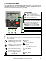
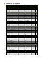
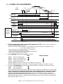
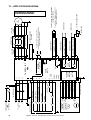
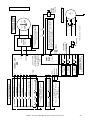
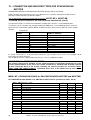
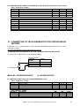
1
TAKEDO - 3VF NXP For asynchronous motors or permanent magnets synchronous motors (with encoder or tachogenerator) USER MANUAL P06 119 20-07-2010 REV. SOFTWARE DATE R.T. Check and Approval A B C QUICK GUIDE TO PUTTING ON DUTY OPEN LOOP ASYNCHRONOUS MOTORS (without encoder) Page 3 QUICK GUIDE TO PUTTING ON DUTY CLOSED LOOP ASYNCHRONOUS MOTORS (with encoder) Page 4 QUICK GUIDE TO PUTTING ON DUTY SYNCHRONOUS MOTORS Page 5 ALPHABETICAL LIST OF CONTENTS ACTIVE FAULTS AND ALARMS Page 15 Par. 6.4 APPLICATION BOARD FOR ASYNCHRONOUS MOTORS Page 12 Par. 5 APPLICATION BOARD FOR SYNCHRONOUS MOTORS Page 36 Par. 12 BRAKING RESISTOR Page 10 Par. 3.1 CLOSED LOOP ADJUSTMENTS Page 31 Par. 11 CLOSED LOOP ASYNCHRONOUS MOTORS Page 29 DIRECT FLOOR ARRIVAL - ASYNCHRONOUS MOTORS Page 32 Par. 11.1 DIRECT FLOOR ARRIVAL - SYNCHRONOUS MOTORS Page 43 Par. 16.2 EMC COMPATIBILITY Page 11 Par. 3.2 EMERGENCY Page 22 Par. 7.10 ENCODER FOR ASYNCHRONOUS MOTORS Page 30 Par. 10 ENCODER FOR SYNCHRONOUS MOTORS Page 38 Par. 13 EXPANSION BOARD Page 18 Par. 6.7 FAN CONTROL Page 19 Par. 7.5 FAULT HISTORY Page 17 Par. 6.5 IDENTIFICATION (OPEN LOOP) Page 19 Par. 7.4 KEYPAD AND MENU Page 13 Par. 6 MAINTENANCE Page 22 Par. 8 MONITOR Page 14 Par. 6.1 ONE FLOOR TRAVEL - ASYNCHRONOUS MOTORS Page 21 Par. 7.8 ONE FLOOR TRAVEL - SYNCHRONOUS MOTORS Page 43 Par. 16.1 OPEN LOOP ADJUSTMENTS Page 20 Par. 7.7 PARAMETERS Page 23 Par. 9 POWER CONNECTION Page 10 Par. 3 PRECAUTIONS Page PRELIMINARY ADJUSTMENTS Page 18 Par. 7.1 - 7.3 PUTTING ON DUTY SYNCHRONOUS MOTORS Page 40 Par. 15 SAFETY WARNINGS Page 9 Par. 2.1 SETTING POWER LIMIT Page 19 Par. 7.6 SPECIAL PARAMETERS - CLOSED LOOP ASYNCH. MOTORS Page 34 Par. 11.2 SPECIAL PARAMETERS - SYNCHRONOUS MOTORS Page 45 Par. 16.3 SYNCHRONOUS MOTOR SETTINGS Page 42 Par. 16 SYNCHRONOUS MOTORS Page 35 SYSTEM MENU Page 17 Par. 6.6 TACHOGENERATOR FOR SYNCHRONOUS MOTORS Page 39 Par. 14 VACON EC CONFORMITY DECLARATION Page 28 2 9 Par. 2.2 TAKEDO - 3VF NXP USER MANUAL Release P06 dated 20-07-2010 A QUICK GUIDE TO PUTTING ON DUTY OPEN LOOP ASYNCHRONOUS MOTORS (without encoder) 1) Make all connections as indicated in the manual. 2) Check the following parameters: Parameter Description Unit SMS setting Value to be set Select according to country of use SMSLift Asyn Value SMS setting Value to be set Value 400 S6.1 Language Italian S6.2 Application SMSLift Asyn 3) Enter data in the following parameters: Parameter 4) Description Unit V P2.1.2 Motor Nominal Voltage P2.1.3 Motor Nominal Frequency Hz 50 Motor rating plate data Motor rating plate data P2.1.4 Motor Nominal Speed RPM 1440 Motor rating plate data P2.1.5 Motor Nominal Current A I Inverter Motor rating plate data P2.1.6 Motor Cos Phi 0.82 Motor rating plate data P2.1.7.1 Lift Rated Speed m/sec P2.1.7.2 Pulley Diameter mm 0.70 520 LIFT data LIFT data P2.1.7.3 Gear Ratio 1.58 LIFT data P2.1.7.4 Ropes Ratio 1:1 LIFT data P2.1.7.5 Update Data No Yes Run IDENTIFICATION Routine: - Set parameter P2.1.8 to 1 and run a call command: the contactors energizes, the brake doesn’t open, and “RUN” lights up. When the “RUN” light goes off, “STOP” appears and parameter P2.1.8 goes to 0, deactivate the call (e.g. by opening the operation valve). 5) If it does not work perfectly, see the full MANUAL. TAKEDO - 3VF NXP USER MANUAL Release P06 dated 20-07-2010 3 B QUICK GUIDE TO PUTTING ON DUTY CLOSED LOOP ASYNCHRONOUS MOTORS (with encoder) 1) Make all connections as indicated in the manual. 2) Check the following parameters: Parameter Description Unit SMS setting Value to be set Select according to country of use SMSLift Asyn Value SMS setting Value to be set Value 400 S6.1 Language Italian S6.2 Application SMSLift Asyn 3) Enter data in the following parameters: Parameter Description Unit V P2.1.2 Motor Nominal Voltage P2.1.3 Motor Nominal Frequency Hz 50 Motor rating plate data Motor rating plate data P2.1.4 Motor Nominal Speed RPM 1440 Motor rating plate data P2.1.5 Motor Nominal Current A I Inverter Motor rating plate data P2.1.6 P2.1.7.1 P2.1.7.2 P2.1.7.3 P2.1.7.4 P2.1.7.5 P2.1.12 Motor Cos Phi Lift Rated Speed Pulley Diameter Gear Ratio Ropes Ratio Update Data Encoder Type m/sec m/sec mm 0.82 0.70 520 1.58 Motor rating plate data LIFT data LIFT data LIFT data LIFT data P2.1.13 Encoder Direction P2.5.1 Motor Control Mode 1:1 No Incremental Not inverted Yes Incremental Not inverted if motor is going up Inverted if motor Open loop is going up Closed Loop If unknown: - for 1/2 speed motors for lifts, enter P2.5.4.1 Magnetizing Current A 0.5 * I Inverter 1/3 of value in P2.1.5 - for motors with inverters, enter P7.3.1.1 Pulse/revolution (Number of encoder pulses) 1024 2/3 of value in P2.1.5 Number of pulses / revolution of installed encoder 4) If it does not work perfectly, see the full MANUAL. 5) For other accessory functions such as POWER LIMIT, ONE FLOOR TRAVEL ONLY, DIRECT FLOOR ARRIVAL etc. see the full manual. 4 TAKEDO - 3VF NXP USER MANUAL Release P06 dated 20-07-2010 C QUICK GUIDE TO PUTTING ON DUTY PERMANENT MAGNET SYNCHRONOUS MOTORS FREE MOTOR, NO CABLES 1 – BRAKE AND BRAKE CONTROL MICRO-SWITCH CONNECTION TAKEDO - 3VF NXP USER MANUAL Release P06 dated 20-07-2010 5 2 – MOTOR AND ENCODER CONNECTION (MAKE EARTH CONNECTIONS AS SHOWN IN THE PHOTOS) 6 TAKEDO - 3VF NXP USER MANUAL Release P06 dated 20-07-2010 3) Check the following parameters: Parameter Description Unit SMS setting S6.1.2 Language Italian S6.2.2 Application SMSLift Sync Value to be set Select according to country of SMSLift Sync Value Value 4) Enter data in the following parameters: Parameter Description Unit V SMS setting Value to be set 400 Hz 8.00 Motor rating plate data Motor rating plate data 60 Motor rating plate data I Inverter Motor rating plate data P2.1.2 Motor Nominal Voltage P2.1.3 Motor Nominal Frequency P2.1.4 Motor Nominal Speed RPM P2.1.5 Motor Nominal Current A P2.1.6 P2.1.7.1 P2.1.7.2 P2.1.7.3 P2.1.7.4 P2.1.7.5 Motor Cos Phi Lift Rated Speed Pulley Diameter Gear Ratio Ropes Ratio Update Data 0.90 1.00 320 1.01 1:1 No Motor rating plate data LIFT data LIFT data LIFT data LIFT data P2.1.12 Encoder Type Incremental P2.1.13 Encoder Direction Not inverted m/sec mm Yes Encoder Type: Incremental or EnDat Not inverted if motor is going up Inverted if motor P2.1.14 Calculated Poles 0 P2.1.16 Motor Rs 0 P2.1.17 Motor Xs 0 P7.3.1.1 Pulse/revolution (Number of encoder pulses) 2048 is going up Make sure the number of poles calculated matches the number for the motor If motor rating is unknown, leave at 0 If motor rating is unknown, leave at 0 Number of pulses / revolution of installed encoder 5) If the encoder is an EnDat type, follow the procedure illustrated in paragraph 15.8 A) of the full MANUAL step by step. 6) If the encoder is an incremental type, follow the procedure illustrated in paragraph 15.8 B) of the full MANUAL step by step. 7) If it does not work perfectly, see the full MANUAL. 8) For other accessory functions such as POWER LIMIT, ONE FLOOR TRAVEL ONLY, DIRECT FLOOR ARRIVAL etc. see the full manual. TAKEDO - 3VF NXP USER MANUAL Release P06 dated 20-07-2010 7 8 TAKEDO - 3VF NXP USER MANUAL Release P06 dated 20-07-2010 1 – INTRODUCTION The TAKEDO–3VF NXP is an inverter drive with built-in EMC filter and smoothing choke, responding to Council Directives 3/89/CEE (electromagnetic compatibility) 336/73/CEE (low voltage equipment). To ensure compliance with EN12015 regarding low frequency harmonics, a further 3% inductance is required. The drive can operate both in open loop and closed loop modes. For operation in closed loop mode, an optional circuit board is required, and an encoder as described in the following pages. This manual provides you with the necessary information about the starting up and operation of the NXP frequency converter. You can find further information about application and installation in a lift control panel in the ANNEX NXP FOR PANEL WIRING SPECIALISTS , available in electronic edition on our website: www.sms.bo.it. 2 – SAFETY WARNINGS AND PRECAUTIONS Full details are available in the original VACON manual (NXP range inverters) which can be consulted at www.it.vacon.com. Read this manual in its entirety before powering up the equipment, following the procedures step by step. In detail, please read the following chapters carefully: 7 – ADJUSTMENT PROCEDURE 6.4 – ACTIVE FAULTS 2.1 SAFETY WARNINGS Follow the procedures indicated below with due care, so as to avoid any risk of serious accident. 1- The leakage current from the inverter to ground is greater than 30mA, and accordingly, the power circuit must incorporate a differential circuit breaker with Id not less than 300mA, type B or type A. Under European directives, the ground connection must use a cable of not less than 10 mm² section. 2- If the parameters used to program the drive are incorrect, the motor may rotate faster than synchronous speed. Do not run the motor beyond its specified electrical and mechanical limits. The installer is responsible for ensuring that movements are generated in conditions of safety, without exceeding specified operating limits. 3- Risk of electrocution. Power up the inverter only with the front cover fitted. NEVER remove the cover during operation. Before carrying out any operation on the equipment, isolate from the electrical power supply and wait a few minutes for the internal capacitors to discharge. 4- The external braking resistor heats up during operation. Do not install it close to or in contact with inflammable materials. To improve heat dissipation it is good practice to fix the resistor to a metal plate. Ensure it is properly protected and cannot be touched. 5- The inverter must always be connected to the mains supply. In case of interruption wait 1 minute at least before restoring the supply. TOO NEAR INSERTIONS OF THE MAINS CAN CAUSE A PERMANENT DAMAGE OF THE INVERTER 2.2 PRECAUTIONS Follow the procedures indicated in the manual with care so as to avoid the risk of damaging or destroying the drive. 1- Do not connect the equipment to a voltage higher than the permissible input voltage. An excessive voltage can cause irreparable damage to internal components. 2- Check the fan regularly: check the air flow is constant and remove and built-up dust. 3- To avoid the risk of damaging the drive in case it stays not working without power supply for a long time, you should follow these precautions: - If the inverter doesn’t work since several months, before starting the operation, regenerate the bus capacitors powering up the drive at least for 1 hour preventing it can operate. - If the inverter doesn’t work since one year or more, to regenerate the bus capacitors power up the drive, preventing it can operate, for 1 hour at an input voltage less than 50% the rated voltage, then for 1 hour at the rated input voltage. 4- Do not connect capacitors to the inverter outputs. 5- If the drive protection functions trip, do not reset the fault before having analysed and removed the cause of the fault. 6- The lift system should be counterweighted at 50%, if counterweighted at 40% the current in up direction with full load is greater and requires a larger capacity inverter to that normally necessary, with consequent greater cost. 7- Use a drive having rated current equal to or greater than the motor rated current . 8- The braking resistor have to be connected between B+ and R-. If connected between B+ and B-, the inverter will be permanently damaged. TAKEDO - 3VF NXP USER MANUAL Release P06 dated 20-07-2010 9 3 – CONNECTING THE POWER CIRCUIT L1;L2;L3 A.C. mains power input L1;L2 D.C. power input U;V;W Inverter output B+;R- External braking resistor Ground Connect the three phases of the power supply to any three terminals, in any order Connect the batteries in the event of emergency operation (evacuation) Connect the three output phases to the contactors, then to the motor. Connect the external braking resistor Connect to the ground system CC terminals Braking resistor terminals Ground terminals Example of power circuit connection Motor cable Mains cable 3.1 SAFETY WARNINGS 1- Ground the unit before powering it. 2- To increase the protection of the internal diodes and connecting wires (especially against the overvoltage due for example to atmospheric phenomena), you should connect three fast-acting fuses (one for each phase) in series with the a.c. power input terminals; fuses must be rated to match the different size designations as indicated in TABLE – Recommended braking resistors and fuses. The fuse kit, complete with box, is available on request. 3- To avoid irreparable damage to the inverter, do not connect braking resistors with resistance or power ratings lower than those indicated in TABLE. For long run lifts or high reverse gain gears, install the braking resistor with oversized power but with the same value in ohms (if needed, contact SMS for advice. !). 4- The inverter drive is connected <<up line>> of the power contactors. The drive is able to pilot operation of the motor in two directions, accordingly, the system can incorporate only two power contactors to switch the inverter – motor line, as prescribed in safety regulations. 5- The external braking resistor heats up during operation. Do not install it close to or in contact with inflammable materials. Ensure it is properly protected and cannot be touched. 6- Wire and bond ground connections in accordance with professional standards (as indicated under heading 3.2) to avoid problems with EMC interference. 7- Take particular care over the power connections. If the input and output connections are reversed, the inverter will be inevitably damaged. NOMINAL CURRENT (A) BRAKING RESISTOR SIZE (kW) FAST ACTING FUSES (A) INVERTER 400 VOLT (380-500V) SERIES VACON CODE 6 14 NXP0013 DIMENSIONS LxHxW (mm) 128x292x190 55 Ask SMS 50Ω 1500W 42Ω 445x110x140 7.5 18 NXP0022 144x391x214 55 50Ω 50Ω 1500W 42Ω 14 27 NXP0032 144x391x214 80 Ask SMS 2x50Ω 1500W 14Ω 445x110x140 445x110x140 (*) 22 46 NXP0061 195x519x237 110 3x50Ω 1500W 3x50Ω 1500W 14Ω 445x110x140 (*) 30 61 NXP0072 237x591x257 140 5x50Ω 1500W 5x50Ω 1500W 6.1Ω 445x110x140 (*) 37 72 NXP0087 237x591x257 140 5x50Ω 1500W 5x50Ω 1500W 6.1Ω 445x110x140 (*) SUPPLIED BY SMS (Geared motor) SUPPLIED BY SMS (Gearless motor) 1500W TABLE – Fuses and recommended braking resistors (*) Full dimension is the one indicated multiplied by the number of resistors. 10 TAKEDO - 3VF NXP USER MANUAL Release P06 dated 20-07-2010 MINIMUM VALUE (Ω Ω) DIMENSIONS LxWxH (mm) IMPORTANT: For high travel (>30m) or gear with high inverse efficiency, install the braking resistor recommended as value in ohm, but power corresponding to the next higher size. For higher powers and voltages, or advice on application, contact SMS.. 3.2 INVERTER/MOTOR CABLING RULES TO ASSURE EMC CONFORMITY The correct INVERTER – MOTOR cabling must follow the rules below: 1- The building ground plant must be connected to both the inverter and motor. 2- The inverter/contactor and contactor/motor cable runs must be as short as possible, shielded with four poles (three phases plus yellow/green ground wire), or four unshielded wires bound together running in a duct or grounded metal tube. In other words, in the same cable or tube there must be a ground wire running as close as possible to the power cables. In the case of a shielded cable the shield must be unbroken between the inverter/contactor and contactor/motor. The shield have to be grounded at both ends with a 360° clamp (Fig. 1), or with special terminals SHEATH ASSEMBLY PANEL SHIELD OMEGA CONNECTOR UNPAINTED AREA 3- 456- 7- 8- 9- If the shield cannot be grounded with a 360° clamp on the motor terminal block itself, the shield must be grounded on the motor casing before the cable enters the terminal box. Use a shielded cable also for the inverter input power line to avoid radiated EMC emissions in the system. The mains input power cables and inverter output cables MUST NOT be run in the same duct and their runs must be as far apart as possible (at least 50 cm. 50 cm.). The power and control cables must be run as far apart as possible and not parallel to each other, even if they are shielded; if the cable runs cross they must do so at an angle of 90°. Independently of the connection to the building grounding plant, the motor casing MUST be connected both to the cable shield and to the yellow/green ground wire inside the shielded cable. The inverter emits electromagnetic radiation which can be captured and transmitted by cables, in particular by the flexible cables in the shaft. To avoid this problem, use shielded cables for the control panel logic / inverter connections, with the shield grounded at both ends. DO NOT use shielded cables without grounding the shields: this leads to higher levels of EMC disturbance than if unshielded cables are used. Any wire in a multi-pole cable which is not in use must be grounded at both ends . Any cable, whether control and external shaft or car connections, must never run parallel/near to the power cable, even if shielded; if they must be parallel for any reason, they should be run through separate metal ducts. The pulse generator cable must be shielded and the shield grounded at the inverter end, as far as possible from the motor cable. The motor/pulse generator coupling must be isolated to avoid parasitic currents looping through the pulse generator. As for all other shields, the ground connection must be via a 360° clamp. All ground connections should be as short as possible and wide . (a) (b) Copper braid (a) is better than wire (b). 10- To avoid unintentional tripping of the differential circuit breakers take the following steps: make the power cable runs as short as possible. Use circuit breakers designed for harmonics (type B or type A, with tripping current 300mA). Reduce the inverter carrier frequency (if possible); the lower the frequency the noisier the motor will be but the smaller the grounding currents and EMC phenomena; motor windings will be less stressed. TAKEDO - 3VF NXP USER MANUAL Release P06 dated 20-07-2010 11 12 Ke TAKEDO - 3VF NXP USER MANUAL Release P06 dated 20-07-2010 + - SHIELDED CABLE RED BLACK ORANGE GREEN BLUE YELLOW N.B.: IN THE OPEN LOOP VERSION, THERE'S NO ENCODER BOARD. B- B+ A- A+ TP1 Ke2 EMERGENCY OPERATION +24VDC I<250mA 10 RO1 26 25 22 23 20 12 19 18 AC AC R- B+ SHIELDED CABLE RELAY OUTPUT Imax<400mA ; Vmax<=125 VDC SHIELDED CABLE RELAY OUTPUT Imax<400mA ; Vmax<=125 VDC SHIELDED CABLE CONTACTOR SWITCH OFF COMMAND or SPEED DETECTOR – OPERATION TB BRAKE CONTACTOR + OPERATION ALARM RELAY To allow emergency operation, these terminals have to be connected to a supply voltage 220VAC (I>300mA). M 3-PH Programmable through par. 2.7.1 (Default = MOTOR SWITCH) SHIELDED EXTERNAL BRAKING RESISTOR GROUND CABLE TP1 OPEN COLLECTOR OUTPUT I<50mA DC ; V=24 Vdc Ke2 SHIELDED CABLE N.B.: THE FILTER AND REACTANCE ARE INSTALLED INSIDE THE INVERTER. TO ENSURE OPTIMUM EMC COMPATIBILITY, INPUT AND OUTPUT CABLES MUST BE SHIELDED. RO2 BOARD NXOPTA2 DO1 (-) (+) EMERGENCY BOARD 102.06.NXEM1 BOARD NXOPTA1 ENCODER 2 BOARD 3 NXOPTA4 (LIine driver) 4 or NXOPTA5 9 (Push-pull) 1 7(GND) 11(CMA) 17(CMB) 6 10 9 8 16 15 14 TAKEDO- 3VF NXP W V U CONTACTORS TP ASYNCHRONOUS MOTORS TP DOWN UP-UPWARD MS-INSPECTION SPEED LS-LOW SPEED HS-HIGH SPEED L3 T SHIELDED CABLE L2 Ke L1 R SHIELDED CABLE Ke2 Three phase S line POWER SUPPLY FROM BATTERIES 5 – BASIC APPLICATION DIAGRAM 6 – KEYPAD AND PROGRAMMING The control panel has an alphanumeric display with nine status indicators and three lines of text for the menu, the descriptions of the menu/submenu and the number of the submenu or the value of the function displayed. There are also nine keys used to control the drive, set parameters and display values. The panel is removable, since all parts are isolated from the a.c. input voltage. Items of data are organized in menus and submenus, by way of which to display and process control signals, indicate faults and measurements and change parameters. STATUS INDICATORS RUN = lights up when the motor is running = indicates the direction of rotation selected STOP = lights up when the motor is at standstill READY = lights up when the drive is powered up and ready for use FAULT = lights up when a fault is detected in the drive ALARM = lights up when an alarm is tripped Indication of position: shows the symbol and number of the menu, the parameter, etc. The I/O term symbol indicates that the I/O terminals have been selected as the control position; in other words, the various commands are given via the I/O terminals. IMPORTANT: When using with lifts, the word Keypad or Bus/Comm must never appear instead of I/O term. Control panel with LCD display Description line: shows the description of the menu, value or fault. Values line: displays numerical values and text for parameters etc. and the number of sub-menus available in each menu. Lights up when power supply is on. Indicates that the inverter is ready. Lights up when the actuator is running. Lights up when a potentially hazardous situation has been encountered following which the actuator was stopped (stopped due to failure). At the same time, the FAULT state indicator light flashes on the display where the fault is described; see Chapter 5.4 - Active Faults. Go back menus. Moves the cursor to the left (in the PARAMETERS menu). Used to quit edit mode. Press and hold for 2…3 seconds to return to the main menu. Menu right Go forward in menus. Moves the cursor to the right (in the PARAMETERS menu). Used to access edit mode. Up arrow Scroll main menu and pages of various submenus. Changes a parameter by increasing the value. enter select Menu left Enter: Confirm selection. Used to reset faults memory: press and hold for 2…3 seconds Select key Toggles between the last two items displayed. Useful for verifying how a newly edited value will impact on another value. START START (NOT used) Down arrow Scroll main menu and pages of various submenus. Changes a parameter by decreasing the value. reset Reset Resets active faults . STOP STOP (NOT used) TAKEDO - 3VF NXP USER MANUAL Release P06 dated 20-07-2010 13 Sub-menus are accessible from the main menu using the key. The M on the first line of the text indicates the main menu. It is followed by a number designating the relative sub-menu. The arrow (→ →) in the bottom right corner of the display indicates an additional sub-menu that can be retrieved by pressing the key. To go back to the main menu from the sub-menu, just press the key. Data are split into menus and submenus on the keypad. Each main menu has seven levels M1 - M7. Press the or keys to go to another menu. M1=Monitor M5=Fault History M2=Parameters M6=System Menu M4=Active Faults M7=Expander Boards Each menu contains submenus, which can also be on several levels. To access the submenus, press the key, then use the +/- keys to show the various quantities; to quit the submenu, press the key. KEY TO SYMBOLS CONTAINED IN MENUS AND SUBMENUS: M= Menu (internal modes G,V,P,H,F) G= Group (internal modes V,P) V= Read only H= Fault history P= Modifiable parameter F= Active faults 6.0 COPYING PARAMETERS USING THE KEYPAD The programming keypad can also be used to copy parameters to or from the inverter. This function is very useful when you need to transfer the optimal parameter set found for a lift on another lift of the same type, but YOU CAN ONLY USE IT TO COPY PARAMETERS BETWEEN INVERTERS EQUIPPED WITH THE SAME APPLICATION SOFTWARE RELEASE (the Application software release is written on a label under the keypad). 6.0.1 – COPYING FROM INVERTER TO KEYPAD Press the left arrow until "M" appears in the top left followed by the menu number (eg. M2). Press the up or down arrow keys to reach M6. Follow the instructions on the display: M6 S6.3 S6.3.2 S6.3.2 S6.3.2 S6.3.2 System menu TransferParam To Panel To Panel To Panel To Panel S1>S8 → P1>P4 → S6.1 appears when you press the right arrow.Press the up arrow until you reach S6.3. S6.3.1 appears when you press the right arrow. Press the up arrow until you reach S6.3.2. Select → Press the right arrow. AllParameters Press enter to start copying parameters. Wait ..... Wait for copying to complete. OK Copying complete. The control panel now contains the inverter data. 6.0.2 – COPYING FROM KEYPAD TO INVERTER The same method as described above applies. Selecting S6.3.3 instead of S6.3.2 results in "From the panel" instead of "To the Panel" being shown on the display. Then continue as before. Note: During the copy from keypad to inverter some data copy will appear as “Locked” . This happens because there are fixed parameters that are not modifiable (reserved). If the Enter key is pressed at any time, “Locked” appears (about 6-7 times), copy continues and “OK” will be displayed. Attention: Copy from a keypad when its data comes from an inverter of the same size of the one you are copying into. Connecting the keypad to the inverter in which you want to copy the data , it will appear: Copy To Panel? enter/reset Push RESET because you want to copy the control panel data to the inverter. 14 Copy From Panel? enter/reset Press ENTER to start copying then wait. TAKEDO - 3VF NXP USER MANUAL Release P06 dated 20-07-2010 6.1 M1 = MONITOR This menu displays values and data during inverter operation and it is split into 3 different sub-menus. The caption V1→ →Vn appears under the name of the menu. This means ‘n’ quantities can be monitored. Content Description s Drive – Motor Content Description s V1.1.1 V1.1.2 V1.1.3 V1.1.4 V1.1.5 V1.1.6 V1.1.7 V1.1.8 V1.1.9 V1.1.10 V1.1.11 Output frequency FreqReference Motor Speed Motor Torque Motor power Motor Current Motor Voltage DC-link Voltage Unit temperature Advan Cont Memory Motor Power (absorbed) Input – Output V1.2.1 DIN1, DIN2, DIN3 Up, Down, Evacuation V1.2.4 V1.2.2 DIN4, DIN5, DIN6 High, Low, Inspection Speed V1.2.5 V1.2.3 DIN7, DIN8 Run Enable, Safety Brake Control V1.2.6 DO1, R01, R02 Programm. outputs: Motor Switch, Fault, Brake RE1, RE2, RE3 NXOPTB5 board programmable outputs: Motor Switch, Motor Block, Speed Detector Analog Iout Ride Values V1.3.1 Lift Speed m/s V1.3.4 V1.3.2 Encoder Freq (Hz) (+ upward, - downward) V1.3.5 V1.3.3 TotalStopDistan (mm) V1.3.6 Slowing Distan (mm) (Slowing-down distance) LowSpeedDistan (mm) (Low speed distance) FinalStopDistan (mm) (Stop distance) Another very useful display is in menu M6 - S6.11.1 = POWER MULTI-MONITOR - pressing this displays motor current for each phase. key 6.2 M2 = PARAMETERS Full list of parameters with associated descriptions is in the paragraph “9 – PARAMETERS LIST”. 6.4 M4 = ACTIVE FAULTS AND WARNINGS Listed below are the most common fault messages. Be careful not to reset the alarm or fault without first having investigated the problems that caused the protection mechanism to cut in. Always deselect the run command before resetting any fault. Code 1 2 5 7 8 9 3 10 11 Description Overcurrent: current 4 times the nominal value detected at the inverter output. Remedies / Indications Check the condition of cables and motor, also the size of the inverter drive. Increase the deceleration time, check the value Overvoltage: bus voltage is too high. of the braking resistor. Charge switch: The charge switch is open when Reset the fault and restart . If the fault happens the drive is in running. again, contact SMS. Cannot be reset from the keypad. Switch off power. DO NOT RE-CONNECT POWER! Saturation trip: several potential causes, Contact manufacturer. If this fault appears including a faulty component. simultaneously with Fault 1, check motor cables and motor. System error: -component damaged Reset the fault and restart . If the fault happens -malfunction again, contact SMS. -Verify data register, see 7.3.4.3. Check that the voltage input to the inverter drive Undervoltage: BUS voltage is too low. is correct and steady. If the fault occurs during acceleration, increase the acceleration time. Power stage faults : detection of fault in power Check the power cables on the input/output sides connections (input or output phase missing, earth and/or the motor insulation . fault, etc) TAKEDO - 3VF NXP USER MANUAL Release P06 dated 20-07-2010 15 Code 12 13 14 16 15 17 22 23 25 26 32 36 37 38 39 40 Description Braking fault: fault affecting braking resistor or chopper. Temperature inverter undertemperature (-10°C) inverter overtemperature (+90°C) motor overtemperature Motor stall: the motor has not started while the inverter has already reached 90% of the limit current settled in P2.1.1. Motor underload EEPROM “Checksum” error: - Parameter recovery failed - Damaged or malfunctioning component Microprocessor watch-dog error: - operational fault - component failure Start up prevented: Start-up of the inverter has been impeded. Fan not working Control unit: The control unit can’t control the power unit and vice versa. Device changed: Optional board or control unit changed. Device added: An optional board or power unit with different nominal rating has been added. Remove device: An optional board or p. ower unit has been removed. Device unknown: Unknown optional board or drive. 41 IGBT temperature: IGBT Inverter Bridge overtemperature protection has detected a short term too high overload current. 43 Encoder error 52 54 Speed Error 57 Overload 59 Wrong run 60 Levelling 61 Low current 62 Emergency 16 Check the brake or the counterweight if the stall happens in down run without load. Make certain the motor is not too small for the rated power of the drive. Reset the fault and restart . If the fault happens again, contact SMS. Reset the fault and restart. If the fault happens again, contact SMS. Cancel prevention of inverter start-up. Contact SMS. Replace the control unit. Reset Reset Reset Check loading. Check motor size. Check brake opening. Check torque at low revs (see paragraph 7.7.1). Channels inverted (modify parameter P2.1.13 “EncoderDirection”); no/faulty connection, or faulty encoder. SUBCODE S6 – in case of PMSM, it means wrong or missing connection to terminals 1-2-3-4, if the encoder type is set to ABSOLUTE (ENDAT) SUBCODE S7 – wrong or missing channel connection SUBCODE S9 – angle identification error in PMSM Keypad communication error: The connection between the control keypad and the frequency converter is broken. Slot error: Optional board or connection slot faulty. 56 Remedies / Indications Check the connection and/or the size of the resistor. Make certain the air flow around the drive is sufficient to cool the heat sink and/or check for possible motor overload. Check keypad connection and possible keypad cable. Check board and slot Contact SMS. . Channels inverted (modify the parameter P2.1.13 “EncoderDirection”) or the motor doesn’t follow the speed curve set by the inverter because of a wrong setting. Motor limit torque exceeded. Verify the working current and the correct brake opening. The run direction (up or down) has been activated for more than 5 seconds without a speed level. Check the control panel commands. Low speed input falls during slow-down, before the motor has reached the steady low speed level The inverter doesn’t open the brake because current doesn’t reach the value set in P2.3.1.1 for open loop or in P2.3.2.1 for closed loop. Emergency input signal falls during the emergency run. TAKEDO - 3VF NXP USER MANUAL Release P06 dated 20-07-2010 Code 63 64 67 68 69 70 71 72 73 74 75 Description Remedies / Indications No current in one phase or unbalanced current in Output phases the output phases. The active speed level has a frequency reference Low reference which is lower than the DC electrical braking start frequency (open loop only). Overspeed The inverter has gone over maximum frequency. Direction commands, and therefore also the Contactors opened too early contactors between the inverter and motor, open (Please see the “Alarm 68 NOTE”). before the inverter switch-off. If you use the ENABLE START input (terminal 2), it indicates that the contactor closed No Enable signal was not given within 2 seconds of the contactor command. After the SMS application software download , Wrong licence code the licence code is not entered correctly. The motor identification or the rotor angle Identification error identification for PMSM has not come correctly to an end.. The safety brake input control has not detected Wrong brake opening the brake opening after the P2.3.4 time. The safety brake input control has not detected Wrong brake closing the brake closing after the P2.3.5 time. In case of PMSM, the brake doesn’t open Wrong Angle identification because the encoder angle identification at start is not correct. In case of PMSM, the brake doesn’t open because there is no good feedback to the initial Phase Check not OK current pulse (maybe a phase is open or the identified angle is not correct) If other types of fault should occur, please contact SMS. Alarm 68 NOTE After 20 trips of this alarm, the drive goes out of service and you need to use RESET key to resume the operation. To check the total amount of the Alarm 68 trips, please see the Menu M1 MONITOR – V1.1.10. Eliminate the malfunction by delaying director command and hence also contactor opening. If you can’t do this (for example, in lifts with manual doors, where people open the car door once the car has stopped), set parameters P2.3.1.5 and P2.3.1.2 to 0. If the fault persists, please contact SMS .. EARLY OPENING OF MOTOR CONTACTOR SHORTENS INVERTER LIFE. INVERTER LIFE 6.5 M5 = FAULT HISTORY The caption H1→Hx appears under the menu. This indicates how many faults are memorized. Up to 30 faults can be memorized and displayed chronologically in reverse order (most recent fault displayed first). Pressing the key when viewing the fault code opens the "Instant fault data register", in which the values of several key variables are saved (e.g. output frequency, motor current, motor torque, etc.) as they occur. Press the or keys to scroll this register. To reset faults, the enter (ENTER) key must be pressed and held for at least 3 seconds. 6.6 M6 = SYSTEM MENU The caption S1→S11 appears under the menu. This means there are 11 submenus. S6.1 Language Setting: ITALIAN / ENGLISH / FRENCH / GERMAN. S6.2 Application Setting: SMSLift Asyn / SMSLift Sync SMS advises against modifying other parameters relative to this MENU. If necessary, contact SMS or use the original manual available at www.vacon.com. TAKEDO - 3VF NXP USER MANUAL Release P06 dated 20-07-2010 17 6.7 M7 = EXPANDER BOARDS The caption G1→G5 appears under the menu. This means there can be up to 5 submenus. The number of submenus depends on the number of optional circuit boards connected. G7.1 NXOPTA1 G1→ →G2 (Board on Slot A) SMS advises against modifying the parameters relative to this submenu. G7.2 →NXOPTA2 G1→ →G1 (digital relay outputs, Slot B) G7.2.1 I/O monitor V1→ →V2 Parameter Description V7.2.1.1 DigOUT:B1 (Digital output B.1) V7.2.1.2 DigOUT:B2 (Digital output B.2) UM Def. - Value u.d.m. Def. - Valore G7.4 NXOPTB5 G1→ →G1 (3 digital relay outputs, Slot D) (OPTIONAL) G7.3.1 I/O Monitor V1→ →V3 Par. Descrizione V7.4.1.1 DigOUT:D1 (Digital output D.1) V7.4.1.2 DigOUT:D2 (Digital output D.2) V7.4.1.3 DigOUT:D3 (Digital output D.3) Menus for ENCODER boards are illustrated in the section on CLOSED LOOP application and for SYNCHRONOUS MOTORS. 7 - ADJUSTMENT PROCEDURE There is a guided procedure in order to set the basic parameters of the motor (SET UP) which starts automatically at the very first switch-on of the drive, or when you modify the Application type (SYSTEM MENU S6.2). Care should be taken however, as the SET UP procedure restores default values of all parameters, cancelling any programmed speed levels or customized input/output configurations that the switchboard engineer may have been set. Before starting to change any parameter or regulation, proceed in this way : 7.1 – Go to the System Menu M6 and check that the right Application is set in S6.2, i.e. referring to the motor you are going to control (ASYNCHRONOUS or PERMANENT MAGNET SYNCHRONOUS). If necessary, change the type of application which will start the SET UP tool. On completion, skip straight to point 7.1 - b). If the right type of application has been set, continue as follows: 7.1 – a) ENTER MOTOR RATINGS DATA IN PARAMETERS P2.1.2 / 3 / 4 / 5 / 6 If the motor rpm at nominal load is not known, or if the nominal value on data plate is 1500 rpm: - if the motor is 1 or 2 speed, or for conventional ACVV regulator, set 1350/1380 rpm - if it is for a VVVF speed regulator, set 1440 rpm. If the cos phii value is not known: - if the motor is 1 or 2 speed, or for conventional ACVV regulator, set 0.76 - if it is for a VVVF speed regulator, set 0.82. 7.1 – b) ENTER LIFT SYSTEM RATINGS DATA IN PARAMETERS P2.1.7.1 / 2 /3 / 4 (speed, pulley diameter, gear ratio, ropes ratio). If parameter P2.1.7.5 (Update Data) is set to "Yes", the maximum frequency (P2.2.1) will be calculated automatically, as well as the various speed levels (high, low, inspection, etc. from P2.2.7 to P2.2.13) and the speed value for one floor travel only (P2.2.20). IMPORTANT Speeds are expressed in frequency (Hz): if you want to see the car speed in m/s for a given frequency, press and release the START key. This check allows you to verify if the lift is set to the required speed. 18 TAKEDO - 3VF NXP USER MANUAL Release P06 dated 20-07-2010 7.2 – PLACE THE DECELERATION COMMANDS AT A DISTANCE FROM FLOOR AS INDICATED IN THE TABLE DECELERATION DISTANCE TABLE Nominal lift speed (m/s) Deceleration distances (mm) 0.6 - 0.8 1.0 1.2 1.4 1.6 1.8 2.0 1000 1400 1700 2000 2200 2600 2800 If the distance is greater than the one shown in the Table, the lift system will operate more smoothly. You can check the actual deceleration distance (distance between the deceleration switch and the stop switch) through the menu M1 MONITOR – V1.3.3 (TotalStopDistance), but this works only if the parameters “Maximum frequency” P2.2.1 and “Lift nominal speed” P2.2.2, corresponding to the maximum frequency, are set in the right way. Also, place the stop switch in the middle position in relation to the floor: The STOPPING DISTANCE TABLE shows guideline values to consider in order to define activation distance of the stop switch (or switches): SINGLE STOP MAGNET FLOOR LEVEL STOPPING DISTANCE TABLE Nominal lift speed (m/s) Total stopping distance (D) (mm) = D 0.6 – 0.8 > 1.0 60 80 = , = means to center the magnet of length ‘D’ at floor level = DOUBLE STOP MAGNET = FLOOR LEVEL D = To enable the DIRECT ARRIVAL AT FLOOR FUNCTION (only available in CLOSED LOOP mode) see paragraphs 11.1 and 16.2, with D ≥ 200mm. 7.3 – SET THE MOTOR CONTROL TYPE : OPEN LOOP OR CLOSED LOOP. 7.4 – IDENTIFICATION (OPEN LOOP ONLY) After entering the correct motor data, you must run the IDENTIFICATION procedure: - Set parameter P2.1.8 to 1 and run a call command: the contactors energizes, the brake doesn’t open, and “RUN” lights on. - When the “RUN” light goes off, “STOP” appears and parameter P2.1.8 goes to 0, deactivate the call (e.g. by opening the operation valve). - Torque parameters are now optimized at low revs if an inverter type motor is actually being used; if it is not, you will often have to manually alter parameter P2.5.3.4 (Intermediate Voltage V/f) to obtain the right torque. Modifying any motor data, it is essential to perform the IDENTIFICATION routine again. 7.5 – FAN CONTROL Set parameter P2.1.9 (fan control) as desired: 0 = Continuous 1 = Start - Runs the fan for 1 further minute after stopping. 2 = Temperature - only works if the inverter reaches a temperature of 45°C. 3 = Speed Cntrl - the fan runs during operation and for 1 minute after stopping, at 3 different speed levels, depending on the heatsink temperature. (< 40°C, between 40 and 50°C, > 50°C) SMS advises not to modify fan operation from the default value (speed control), in order to assure a good cooling of the power part at each run of the lift. TAKEDO - 3VF NXP USER MANUAL Release P06 dated 20-07-2010 19 7.6 – SETTING POWER LIMIT The maximum power absorbed by the motor for any load condition can be set. If the maximum power available is less than the maximum power required by the motor, the inverter will reduce speed to get the required result. Obviously arrival at the floor and distance travelled at low speed remain the same whatever the car speed. The parameters that enable this kind of movement are P2.1.18 and P2.4.6. P2.1.18 MAXIMUM POWER When set to 200% (default) it will have no effect. If set to a value less than 100%, power draw will be limited to a set value, as a percentage of the power drawn by the motor at nominal voltage (P2.1.2), nominal current (P2.1.5) and nominal cosφ (P2.1.6). The actual power absorbed from the mains is shown on M1 MONITOR - V.1.1.11. P2.4.6 When the power limit is enabled (P2.1.18 < 100%) , first the motor accelerates then slows down to stay within the maximum allowed power, set P2.4.6 to a value below the default one until optimum function is obtained. 7.7 – OPEN LOOP ADJUSTMENTS 2.2.4 2.2.14 SPEED PROFILE 2.2.15 2.2.3 2.2.17 2.2.16 2.3.1.6 2.2.5 2.2.7 2.2.8 2.3.1.7.5 2.3.1.3 HIGH SPEED COMMAND –terminal 14 LOW SPEED COMMAND - terminal 15 DIRECTION COMMAND - terminal 8/9 0.4s BRAKING TIME AT START 2.3.1.4 ELECTRIC BRAKE BRAKE TIME AT STOP 2.3.1.5 0.3s MOTOR CONTACTORS When parameters 2.3.1.1 and 2.3.1.7.2 are matched, the brake open delay starts. SMOOTH START TIME 2.3.1.6 SMOOTH START FREQUENCY SAFETY BRAKE CONTROL DELAY BRAKE OPENING DELAY AT START 2.3.1.7.3 BRAKE CLOSING DELAY AT STOP 2.3.1.2 SAFETY BRAKE CONTROL RELAY MECHANICAL BRAKE MECHANICAL DELAY BRAKE OPENING After completing what was indicated at points 7.1/2/3/4/5/6/7/8 , proceed as follows: IMPORTANT: Parameters have to be changed ALWAYS ONCE AT A TIME. 20 TAKEDO - 3VF NXP USER MANUAL Release P06 dated 20-07-2010 MECHANICAL DELAY BRAKE CLOSING 1 - Adjust the starting with brake control parameters JERK 2.3.1.7.3 Brake open delay 2.3.1.7.5 Smooth start frequency. 2.3.1.7.6 Smooth start time. BACK ROTATION = = Starting comfort has to be ‘soft’, without jerks nor back rotations. - If a higher torque is needed at the start, increase the value in parameter P2.5.3.4 V/f Intermediate Voltage by one or two units; you must check however afterwards that motor current at start up does not reach the limit set in P.2.2.1 and that current at low speed does not exceed the nominal rated current of the motor and/or inverter. - If the lift does not work as required, contact SMS technical assistance.. 2 - During the high speed run, the rpm of the motor must reach the required rpm value, and the speed of the lift has to be constant. If it is not constant (oscillating), increase or decrease the value of the parameter P2.1.4 (Motor speed), increasing the number of revolutions. 3 - Check now that when slowing down, the lift reaches the floor running for a short space at constant speed (10cm max.) without oscillations or vibrations, with the same speed for both up and down directions and in any load condition. If speed drops under load, decrease the value of P.2.1.4. Adjust the space travelled at low speed with parameter 2.2.4 (Deceleration ramp). 4 - If at floor arrival, the car is not perfectly aligned at floor, the parameters to be adjusted are: It stops BEFORE 2.2.5 2.2.8 2.3.1.6 It stops AFTER Final deceleration ramp Low speed level Stop DC braking current IMPORTANT For low speed frequency, a value of 1/10 of the rated frequency is suggested: Example – low speed set at 5Hz if motor rated frequency is equal to 50 Hz. 7.8 – SINGLE FLOOR TRAVEL The single floor travel function will only be effective if the sequence of commands used in paragraphs 7.7, 11 and 16 is followed, i.e. the normal logic of a 2-speed control board is applied: HIGH SPEED start with input 14 active, then switch to LOW SPEED activating input 15 and disabling 14. TWO SPEED LEVELS MUST NEVER BE INSERTED AT THE SAME TIME. When the desired starting and stopping comfort has reached and, running between far floors, the space travelled at low speed is the same for any floor for both up and down direction, you have to set the slowing distance, especially useful for one floor travel, with parameter P2.2.19 as follows: - Set parameter P2.2.18 to 1. - Make a car call for 2 floors at least. - When the lift reaches a low speed, P2.2.18 will return automatically to 0, while the distance travelled on switching from high to low speed will be saved in P2.2.19 and displayed in V1.3.4. - Make a car call for one floor only, verify comfort, and check that the space travelled at low speed is the same as a travel between far floors . To increase comfort further, decrease parameter P2.2.20 (Half floor frequency). 7.9 – MOTOR NOISE In case of motor noise , increase switching frequency P2.5.2, considering that higher is the frequency, higher are EMC emissions. In addition, the motor insulation and the inverter power components are more “stressed”. TAKEDO - 3VF NXP USER MANUAL Release P06 dated 20-07-2010 21 7.10 – PARAMETERS ONLY EFFECTIVE FOR EMERGENCY OPERATION WITH BATTERY POWER SUPPLY The minimum allowed battery voltage is 48V for ASYNCHRONOUS motors, 96V for SYNCHRONOUS motors. There are several synchronous motors though, which need higher voltage in emergency operation (up to 200V). 2.10.1 EVACUATION MODE: 0 = NOT USED (EMERGENCY FEATURE EXCLUDED) 1 = MANUAL (DOES NOT SELECT FAVOURABLE RUN DIRECTION) 2 = AUTOMATIC (SELECTS FAVOURABLE RUN DIRECTION) EMERGENCY WITH PEOPLE ONBOARD Regardless of the value set in P2.10.1, for the synchronous motors, you can enable another type of emergency operation, the CONSTANT PRESSURE PUSH BUTTON EMERGENCY. To enable this operation, only the control part of the inverter needs to be supplied (not the power section); set parameter P2.10.10 (see below) to anything but 0, and activate simultaneously the up and down commands (of course in addition to the emergency input). The inverter will activate the brake command output only, while the control panel must supply the brake circuit with the proper voltage and make a by-bass on the main motor contactors in the brake circuit. These operations enables the brake opening so that the car runs in the direction where the motor is pulled by the load; the TBM contactor, which makes a short-circuit between the motor windings at stop, doesn’t energize, so that the car runs at reduced speed. Moreover, the inverter checks the car speed doesn’t exceed the speed limit set in P2.10.10: in case the car speed goes over this limit, the inverter makes the brake to close, then makes it to open again after a few seconds, and goes on this way, with a jogging operation, until the up/down commands stay on, allowing the car to stop at a floor level without reaching a dangerous speed. The control panel manufacturer should provide the appropriate audio-visual signalizations, to give warning the car has reached the floor. 2.10.3 MAXIMUM SPEED IN EVACUATION: this is the maximum speed of the motor, whatever the level effectively activated (high, low, inspection, etc.). 2.10.9 SWITCHING FREQUENCY. (maintain the default value). 2.10.10 MAXIMUM SPEED WITH PEOPLE ONBOARD (CONSTANT PRESSURE PUSH BUTTON EMERGENCY OPERATION) This is the maximum speed, expressed in m/sec, which the car mustn’t exceed during the constant pressure push button operation. It’s adjustable from 0 to the nominal speed set in P2.2.2. If it is set to 0, the constant pressure push button emergency operation with people present is DISABLED. 2.10.11.1 MOTOR CONTROL MODE: (FREQUENCY, OPEN LOOP, CLOSED LOOP). If the input supply voltage is lower than 96V, frequency control is the preferred mode in an evacuation situation; For PM synchronous motors you must always select the closed loop control. 2.10.11.2 CURRENT CONTROL DELAY: is the delay between start and the control of the current when inverter chooses the run most favourable direction. During emergency operation, whatever is the selected operation, the inverter display automatically shows the car speed in m/sec, showing also the run direction. 8 – CHECKS AND MAINTENANCE To ensure long service life and smooth operation of the drive, carry out the following checks at regular intervals. Always isolate the drive from the power supply and make certain the keypad is off before proceeding. 1- Remove the dust that collects on the cooling fans and on the control circuit board, preferably by means of compressed air or using a vacuum cleaner. 2- Check that there are no screws loose at the power or control terminals. 3- Check that inverter function is <<normal>> and there is no abnormal overheating. 7.1 MEGGER TEST When performing insulation tests using a Megger tester on the input/output cables or on the motor, remove all the connections to all terminals of the drive and perform the test only on the power circuit, in accordance with the adjacent diagram. Do not Megger test the control circuits. 22 TAKEDO - 3VF NXP USER MANUAL Release P06 dated 20-07-2010 INVERTER 9 – PARAMETER LIST (M2 Menu) IMPORTANT: Parameters with a grey background should only be modified when advised by SMS! Contents Description SMS settings (Asynch. motor) SMS settings (Synch. motor) User setting Unit G2.1 BASIC PARAMETERS P 2.1.1 P 2.1.2 P 2.1.3 P 2.1.4 P 2.1.5 P 2.1.6 Current Limit Motor Nom Voltg Motor Nom Freq Motor Nom Speed Motor Nom Currnt Motor Cos Phi 1.8 * I Inverter 380 50 1440 I Inverter 0.82 1.8 * I Inverter 400 8.00 60 I Inverter 0.9 A V Hz rpm A m/s mm G2.1.7 LIFT DATA P 2.1.7.1 P 2.1.7.2 P 2.1.7.3 P 2.1.7.4 P 2.1.7.5 Lift Rated Speed Pulley Diameter Gear Ratio Ropes Ratio Update Data 0.70 520 1.58 1:1 No 1,00 320 1.01 1:1 No P 2.1.8 P 2.1.9 P 2.1.10 P 2.1.11 P 2.1.12 P 2.1.13 P 2.1.14 P 2.1.15 P 2.1.16 P 2.1.17 P 2.1.18 Identification Fan control ParEditPassword Motor Type Encoder Type EncoderDirection Calculated Poles ForcedPolesNum Motor Rs Motor Xs Max Power 0 3 / Speed control 0 0 / Async Induct 0 / Incremental Not Inverted 4 0 0,00 0,00 300,0 0 3 / Speed control 0 1 / PMSM 0 / Incremental Not Inverted 16 0 0,00 0,00 300,0 50 0.70 2.50 2.00 0.50 0,00 50 5.00 25.00 25.00 25.00 25.00 25.00 2.00 0.6 0.6 1.20 0 1000 25.00 8.00 1.00 2.50 2.00 0.80 0,00 8.00 0.80 4.00 4.00 4.00 4.00 4.00 1.20 0.6 0.6 1.20 0 1000 4.00 Hz m/s s s s Hz Hz Hz Hz Hz Hz Hz Hz s s s s 0,00 0.30 0.50 0.700 0.400 0 0.50 0.050 0 0 0 0 / No 0.00 0.10 0.50 1.00 0.200 0 0.10 0.20 0 0 0 0 / No s Hz s s s mm Hz s Hz mm Hz Ohm Ohm % G2.2 RUN CONFIGURATION P 2.2.1 P 2.2.2 P 2.2.3 P 2.2.4 P 2.2.5 P 2.2.6 P 2.2.7 P 2.2.8 P 2.2.9 P 2.2.10 P 2.2.11 P 2.2.12 P 2.2.13 P 2.2.14 P 2.2.15 P 2.2.16 P 2.2.17 P 2.2.18 P 2.2.19 P 2.2.20 Max Frequency NominalLinSpeed Acceleration ramp Deceleration ramp Final Decelerat. v0 000 zero v1 100 high v2 010 low v3 110 high+low v4 001 inspect. v5 101 high+insp v6 011 low+insp v7 111 hi+lo+ins Acc Inc Jerk Acc Dec Jerk Dec Inc Jerk Dec Dec Jerk Auto HalfF Dist Half Floor Dist Half Floor Freq mm Hz G2.2.21 CLOSED LOOP P 2.2.21.1 P 2.2.21.2 P 2.2.21.3 P 2.2.21.4 P 2.2.21.5 P 2.2.21.6 P 2.2.21.7 P 2.2.21.8 P 2.2.21.9 P 2.2.21.10 P 2.2.21.11 P 2.2.21.12 SmoothStartTime SmoothStartFreq Initial Acceler. 0 Hz TimeAtStart 0 Hz TimeAtStop Stop Distance Final Stop Speed Final Stop Time Initial Speed TotalDecDistance OptimStopSpeed Test Mode TAKEDO - 3VF NXP USER MANUAL Release P06 dated 20-07-2010 23 Contents SMS settings (Asynch. motor) Description SMS settings (Synch. motor) User setting Unit G2.3 BRAKE CONTROL G2.3.1 OPEN LOOP 10.0 0.30 0.7 * I Inverter 0.000 0.400 1.50 2.0 0.30 0.7 * I Inverter 0.000 0.400 0.20 P 2.3.1.1 P 2.3.1.2 P 2.3.1.3 P 2.3.1.4 P 2.3.1.5 P 2.3.1.6 MinCurrBrakeOpen BrakeCloseDelay DC-Brake Current Start DC-BrakeTm Stop DC-BrakeTm Stop DC-BrakeFr % s A s s Hz P 2.3.1.7.1 Reserved 0 0 P 2.3.1.7.2 P 2.3.1.7.3 MinFreqBrakeOpen BrakeOpenDelay 0,00 0.00 0,00 0.00 Hz s P 2.3.1.7.4 P 2.3.1.7.5 P 2.3.1.7.6 MinFreBrakeClose SmoothStartFreq SmoothStartTime 0.50 0.30 0.30 0.10 0.00 0.00 Hz Hz s 10.0 0 0.00 0.50 0.30 0.00 0 0.00 0.10 0,00 % 0.50 0.15 0.00 0.15 s Hz 0 / Not Used 0.50 2.00 2 / NormClosed 2.00 2.00 s s G2.3.1 ADVANCED FUNCTIONS G2.3.2 CLOSED LOOP P 2.3.2.1 P 2.3.2.2 P 2.3.2.3 P 2.3.2.4 P 2.3.2.5 MinCurrBrakeOpen Reserved MinFreqBrakeOpen MinFreBrakeClose BrakeCloseDelay Hz Hz s G2.3.2.6 ADVANCED FUNCTIONS P 2.3.2.6.1 BrakeOpenDelay P 2.3.2.6.2 MaxFreq If Close G2.3 BRAKE CONTROL P 2.3.3 BrakeExt SuperV P 2.3.4 MaxOpenTime P 2.3.5 MaxCloseTime G2.4 DRIVE CONTROL P 2.4.1 Brake Chopper 1 / Test Ready 1 / Test Ready P 2.4.2 Reserved 0 0 P 2.4.3 Undervolt Contr 0 / Off 0 / Off P 2.4.4 SpecialPowerUnit 0 / No 0 / No P 2.4.5 SPU Overload 180 180 % P 2.4.6 Power Meas. % 80 80 % 1 / Open Loop 10.0 2 / Closed Loop 8.0 kHz 1 / AutoTorqBoost 2 / Programmable 1.75 5.00 3.50 0 / None 0 / Linear 0 0 0 Hz % % G2.5 MOTOR CONTROL P 2.5.1 P 2.5.2 Motor Ctrl Mode Switching Freq G2.5.3 OPEN LOOP P 2.5.3.1 P 2.5.3.2 P 2.5.3.3 P 2.5.3.4 P 2.5.3.5 U/f Optimization U/f Ratio Select U/f Mid Freq U/f Mid Voltg Zero Freq Voltg P 2.5.3.6.1 P 2.5.3.6.2 P 2.5.3.6.3 P 2.5.3.6.4 P 2.5.3.6.5 P 2.5.3.6.6 P 2.5.3.6.7 P 2.5.3.6.8 Field WeakngPnt Voltage at FWP VoltStabGain VoltStabDamp TorqStabGain TorqStabDamp MotorBoostGain GeneratBoostGain G2.5.3.6 ADVANCED FUNCTIONS 50 100 100 900 100 800 67 50 8.00 100 100 900 100 980 67 50 Hz % % % G2.5.3.7 ADVANCED FUNCTIONS 1 P 2.5.3.7.1 P 2.5.3.7.2 P 2.5.3.7.3 P 2.5.3.7.4 P 2.5.3.7.5 24 Speed Control Kp Speed Control Ki LowSp.SwitchFreq LowSp. Level Current at 0Hz 3000 300 6.0 5.00 50 3000 300 6.0 0.80 50 TAKEDO - 3VF NXP USER MANUAL Release P06 dated 20-07-2010 kHz Hz % Contents Description P 2.5.3.7.6 RsVoltDrop P 2.5.3.7.7 P 2.5.3.7.8 LsdVoltDrop LsqVoltDrop P 2.5.4.1 P 2.5.4.2 P 2.5.4.3 P 2.5.4.4 P 2.5.4.5 P 2.5.4.6 P 2.5.4.7 P 2.5.4.8 SMS settings (Asynch. motor) Different from 0, it depends on the size ” ” G2.5.4 CLOSED LOOP MagnCurrent 0.5 * I Inverter Adaptive Lim 1 0.10 Adaptive Lim 2 0.50 Speed Cntrl Kp 1 40 Speed Cntrl Ti 1 40.0 Speed Cntrl Kp 2 20 Speed Cntrl Ti 2 40.0 Encoder1FiltTime 0 G2.5.4.9 ADVANCED FUNCTIONS P 2.5.4.9.1 P 2.5.4.9.2 P 2.5.4.9.3 P 2.5.4.9.4 P 2.5.4.9.5 P 2.5.4.9.6 P 2.5.4.9.7 P 2.5.4.9.8 P 2.5.4.9.9 P 2.5.4.9.10 P 2.5.4.9.11 P 2.5.4.9.12 CurrentControlKp CurrentControlTi LoadDrooping Droop time const SpeedDerivative DerivatFilterTime RollBackCtrGain RollBackThresh DC Ripple Compen DC RippleC Gain Multipl Encoder Encoder Divider 40 2.5 0,00 0,000 1.00 0 300 0,10 Enabled 0 1 1 SMS settings (Synch. motor) Different from 0, it depends on the size ” ” User setting Unit 0 0.10 0.20 10 40.0 10 40.0 0 A Hz Hz 100 2.5 0,00 0,000 0.50 50 300 0,10 Enabled 0 1 1 % ms % s s ms ms ms ms % G2.5.5 PMSM (Permanent Magnet Synchronous Motor) P 2.5.5.1 P 2.5.5.2 P 2.5.5.3 Reserved Reserved EncoderCalibrat 0 0 0 P 2.5.5.4 Encoder Angle 0 P 2.5.5.5 P 2.5.5.6 P 2.5.5.7 Flux Current Kp Flux Current Ti Modulator type 3,00 20.0 0 / ASIC P 2.5.5.8 Angl id at Start 0 / Disabled P 2.5.5.9 P 2.5.5.10 P 2.5.5.11 P 2.5.5.12 P 2.5.5.13 P 2.5.5.14 P 2.5.5.15 P 2.5.5.16 RidesAngleIdRefr StartAngleCurren Torque Fall Time Speed limit Speed Lim factor Max Synchro Err RotorPositCorrec Repeat ID Emerg 200 50 0.6 0 / Disabled 100.0 10.0 0 / No 1 / Yes 0 0 0 0 (To be calibrated for EnDat, leave 0 for sin-cos) 3.00 20.0 1 / SpaceVector 0 / Disabled for EnDat, 1 / Enabled for sin-cos 200 50 0.80 0 / Disabled 100.0 10.0 0 / No 1 / Yes 0 / Fwd-Back 0 / Fwd-Back % ms % s % % G2.6 INPUT SIGNALS P 2.6.1.8 Start/StopLogic G2.6.2 SPEED SEL INPUTS P 2.6.2.1 Speed Sel Input1 DigIN:A.4 DigIN:A.4 P 2.6.2.2 Speed Sel Input2 DigIN:A.5 DigIN:A.5 P 2.6.2.3 Speed Sel Input3 DigIN:A.6 DigIN:A.6 P 2.6.2.4 StableDinTime 300 300 ms G2.6.3 FUNCTIONS P 2.6.3.1 Ext Fault Close DigIN:0.1 DigIN:0.1 P 2.6.3.2 Ext Fault Open DigIN:0.1 DigIN:0.1 P 2.6.3.3 Fault Reset DigIN:0.1 DigIN:0.1 P 2.6.3.4 Run Enable DigIN:0.1 DigIN:A.7 P 2.6.3.5 BrakeExt SuperV DigIN:0.1 DigIN:A.8 NOTE: Parameters in groups G2.4, G2.6, G2.8 are only visible if the right password is entered in parameter P2.1.10. TAKEDO - 3VF NXP USER MANUAL Release P06 dated 20-07-2010 25 Contents SMS settings (Asynch. motor) Description SMS settings (Synch. motor) User setting Unit G2.7 OUTPUT SIGNALS P 2.7.1 P 2.7.2 P 2.7.3 P 2.7.4 P 2.7.5 DO1 Content DO1 Inversion DO1 Delay FreqSupervLimit FreqSupervValue G2.7.6 ADVANCED FUNCTIONS P 2.7.6.1 P 2.7.6.2 P 2.7.6.3 P 2.7.6.4 P 2.7.6.5 P 2.7.6.6 P 2.7.6.7 P 2.7.6.8 P 2.7.6.9 P 2.7.6.10 P 2.7.6.11 P 2.7.6.12 Iout Content Iout Filter Time Iout Invert Iout Minimum Iout Scale RO1 Content RO1 Inversion RO1 Delay RO2 Content RO2 Inversion MotorTorqSuperV GenerTorqSuperV 15 / Contactor 0 / Off 0.00 1 / Low Limit 30 15 / Contactor 0 / Off 0,00 1 / Low Limit 5.00 12 / Brake 0.00 0 / Not inverted 0 / 0 mA 100 4 / FaultInvert 0 / Off 0.00 13 / Brake 0 / Off 200.0 200.0 12 / Brake 0.00 0 / Not inverted 0 / 0 mA 100 4 / FaultInvert 0 / Off 0.00 13 / Brake 0 / Off 200.0 200.0 15 / Contactor 16 / MotorContactorDelay 11 / Vel Supervis 15 / Contactor 16 / MotorContactorDela 11 / Vel Supervis 1 / Low Limit 30 1 / Low Limit 5.00 s Hz s % s % % G2.7.7 OPTIONAL OUTPUTS P 2.7.7.1 P 2.7.7.2 P 2.7.7.3 P 2.7.7.4 P 2.7.7.5 Opt RO1 Content Opt RO2 Content Opt RO3 Content FreqSupervLimit FreqSupervValue Hz G2.8 PROTECTIONS 26 P 2.8.1 External Fault 2 / Fault 2 / Fault P 2.8.2 Input Phase Supv 2 / Fault 2 / Fault P 2.8.3 UVolt Fault Resp 1 / Not saved 1 / Not saved P 2.8.4 OutputPh. Superv 0 / None 0 / None P 2.8.5 Earth fault 2 / Fault 2 / Fault P 2.8.6 Motor Therm Prot 2 / Fault 0 / None P 2.8.7 MTP AmbTempFact 0.0 0.0 % P 2.8.8 MTP 0Hz Cooling 40.0 40.0 % P 2.8.9 MTP MotTimeConst 45 45 min P 2.8.10 MTP MotDutyCycle 100 100 % P 2.8.11 Stall Protection 2 / Fault 0 / None P 2.8.12 Stall Current 1.8 * I Inverter 1.8 * I Inverter A P 2.8.13 Stall Time Lim 6.00 6.00 s P 2.8.14 Stall Freq Lim 6.00 6.00 Hz P 2.8.15 Reserved 0 0 P 2.8.16 Reserved 0 0 P 2.8.17 Reserved 0 0 P 2.8.18 Reserved 0 0 P 2.8.19 ThermistorF.Resp 0 / None 0 / None P 2.8.20 Reserved 0 0 P 2.8.21 SlotComFaultResp 2 / Fault 2 / Fault P 2.8.22 Reserved 0 0 P 2.8.23 Speed Fault 2 / Fault P 2.8.24 Speed Error Lim 1/10 nom. motor freq. P 2.8.25 Speed Error Time 2.00 2 / Fault 1/10 nom. motor freq. 2.00 P 2.8.26 Over Torq Fault 0 / None 0 / None P 2.8.27 Torq SuperV time 0,00 0,00 P 2.8.28 RunErrorResponse 1 / Alarm 1 / Alarm P 2.8.29 LowCurrResponse 1 / Alarm 1 / Alarm P 2.8.30 LevellingRespons 1 / Alarm 1 / Alarm P 2.8.31 UnitTemperatSens 0 / Active 0 / Active P 2.8.32 Max Overspeed 110.0 110.0 TAKEDO - 3VF NXP USER MANUAL Release P06 dated 20-07-2010 Hz s s % Contents SMS settings (Asynch. motor) Description SMS settings (Synch. motor) P 2.8.33 AdvancContFault 20 20 P 2.8.34 LowRefResponse 2 / Fault P 2.8.35 EncoderSupervis 1 / Disabled P 2.8.36 PMSM Phase Check 30.0 2 / Fault 0 / Enabled for EnDat encoder 1 / Disabled for sine-cos encoder 30.0 User setting Unit % G2.10 EVACUATION P 2.10.1 P 2.10.2 P 2.10.3 P 2.10.4 P 2.10.5 P 2.10.6 P 2.10.7 P 2.10.8 P 2.10.9 P 2.10.10 Evacuation Mode 2 / Automatic Evacuation Input DigIN:A.3 MaxSpeedInEva 5.00 U/f Optimization 1 / AutoTorqBoost U/f Mid Freq 1.75 U/f Mid Voltg 5.00 Zero Freq Voltg 3.50 MagnCurrent 0.5 * I Inverter Switching Freq 3.0 Man MaxSpeed 0,00 G2.10.11 ADVANCED FUNCTIONS P 2.10.11.1 Motor Ctrl Mode 0 / Frequency P 2.10.11.2 CurrentReadDelay 2.0 2 / Automatic DigIN:A.3 0.80 1 / AutoTorqBoost 0.00 0.00 0.00 0 3.0 0.00 2 / Closed Loop 3.0 TAKEDO - 3VF NXP USER MANUAL Release P06 dated 20-07-2010 Hz Hz % % A kHz m/s s 27 28 TAKEDO - 3VF NXP USER MANUAL Release P06 dated 20-07-2010 ASYNCHRONOUS MOTORS CLOSED LOOP TAKEDO - 3VF NXP USER MANUAL Release P06 dated 20-07-2010 29 10 – CONNECTION AND ENCODER TYPES FOR ASYNCHRONOUS MOTORS When operating in closed-loop mode, the inverter drive requires a feedback signal provided by an industrial encoder, resolution 1024 pulse/rev (encoders with other resolutions can also be used), of type : Line driver powered at 5Vdc or Push-pull powered at 15 or 24 V. Depending on the type of encoder used, the relative board must be inserted inside the inverter: For LINE DRIVER 5V encoders with board NXOPTA4 For PUSH-PULL 15 / 24V) encoders with board NXOPTA5 The board must be inserted in the 3rd connector from the left (slot C) SMS can supply a LIKA I581024H encoder, 1024 pulse/rev , that works with both NOXOPTA4 and NXOPTA5 boards , working in line driver mode if powered at 5Vdc , push-pull mode if powered at 24 Vdc. TERMINAL SIGNAL LIKA I581024H ENCODER terminal 01 A+ YELLOW terminal 02 A- BLUE terminal 03 B+ GREEN terminal 04 B- ORANGE terminal 09 – Power supply BLACK terminal 10 + Power supply RED ADVICE FOR ALL THE ENCODER TYPES The encoder cable must be shielded, and the shield connected (as indicated in paragraph 3.2) to the inverter ground terminal. In any event, the encoder should have a shielded cable of length sufficient to allow connection direct to the inverter, following the shortest possible run and located WELL AWAY FROM THE POWER CABLES. Remaining wires have to be isolated one by one and left unconnected. MENU M7 = EXPANSION BOARD for ENCODER BOARDS NXOPTA4 and NXOPTA5 G7.3 NXOPTA4 G1→ →G2 (5V line driver encoder) or NXOPTA5 G1→ →G2 (push-pull encoder) (Slot C) G7.3.1 Parameters P1→ →P3 Parameter Description P7.3.1.1 Pulse/revolution (Number of encoder pulses) P7.3.1.2 Invert direction (Encoder direction) P7.3.1.3 Reading rate (Encoder sampling) G7.3.2 Monitor V1→ →V2 Parameter Description V7.3.2.1 Encoder frequency V7.3.2.2 Encoder speed 30 UM ms UM Hz rpm TAKEDO - 3VF NXP USER MANUAL Release P06 dated 20-07-2010 Def. 1024 No 5 Value Def. Value 11 – CLOSED LOOP ADJUSTMENTS SPEED PROFILE 2.2.21.3 2.2.16 2.2.15 2.2.14 2.2.3 2.2.4 2.2.17 2.2.7 2.2.5 2.3.2.4 2.2.8 2.2.21.2 HIGH SPEED COMMAND - terminal 14 LOW SPEED COMMAND - terminal 15 DIRECTION COMMAND - terminals 8/9 TIME AT START 2.2.21.4 STOP AT STATIC POSITION 0.4s TIME AT ARRIVAL 2.2.21.5 0.4s MOTOR CONTACTORS When parameter 2.3.2. is matched the brake open delay starts. SMOOTH START TIME 2.3.1.6 SMOOTH START FREQUENCY SAFETY BRAKE CONTROL DELAY BRAKE OPENING DELAY AT START 2.3.2.6.1 BRAKE CLOSING DELAY AT STOP 2.3.2.5 SAFETY BRAKE CONTROL MECHANICAL BRAKE MECHANICAL DELAY BRAKE OPENING MECHANICAL DELAY BRAKE CLOSING 1 - Set the magnetising motor current with parameter 2.5.4.1: if this current is unknown, it is possible to find it with this procedure : - Balance the car load (motor torque the same for both up and down directions, with opposite sign + up – down, viewable in V1.1.4) - Set the inverter in V/F control mode (P2.5.1 = Frequency) - Set speed to half the rated motor frequency - Read the current absorbed at constant speed at half distance - Set the value found in parameter P2.5.4.1 2 - Adjust starting comfort with the following parameters : JERK BACK ROTATION 2.2.21.3 Initial acceleration ramp -2.2.21.4 Hz time at start (about 0.7”) 2.3.2.6.1 Brake open delay (min. 0.5”) 2.5.4.9.7 RollBack Control Gain -Starting comfort has to be ‘soft’, with no jerks or vibrations, or roll back. Check the RollBack Control Gain (P2.5.4.9.7 and 8) (generally, the default value works very well). 3 - If during the acceleration or during high speed travel motor has vibrations, check the parameters : 2.5.4.6 Speed control KP2 2.5.4.7 Speed Control TI2 Check also that the encoder connections have been made as indicated in paragraphs 3.2.8 and 10. The encoder cable must be separated from the power cable and distant 50 cm at least from the motor cable. It should be connected with a single cable, with no added terminals, and with the shield connected to earth at the inverter side. Encoder pulses per revolution must match the relative parameter of the Encoder Board. Check that parameter P7.3.1.3 is set to 5ms for incremental encoder (NXOPTA4/A5) and that there is a good mechanical coupling between encoder and the fast motor shaft (joint, alignment, tight screws etc.) TAKEDO - 3VF NXP USER MANUAL Release P06 dated 20-07-2010 31 4 - Check the slowing phase. The lift must reach the floor in a very small space (few centimetres) , at constant speed without oscillations or vibrations, both for up and down directions. Adjust the space travelled at low speed with parameter 2.2.4 (Deceleration ramp). IMPORTANT: Considering the high precision of the inverter, it is important to set the position of the slowing command with the best possible accuracy, to have the same space travelled at low speed for any floor. 5 - If, at floor arrival, the car is not perfectly aligned with the floor, even if the stop switches are centred to the floor, the parameters to be adjusted are: If it stops BEFORE If it stops AFTER 2.2.5 Final deceleration ramp 2.2.8 Low speed level A very good comfort can be obtained (for a 50 Hz rated frequency lift motor) with a 3Hz low speed and a 0,8 seconds final deceleration(P2.2.5). 11.1 – DIRECT FLOOR ARRIVAL FUNCTION This function is available for all types of motor, for CLOSED LOOP configuration. To enable it, parameter P.2.2.21.6 "stop distance" must be set at a value different from 0 and equal to the stopping distance (distance ½ D - see figure below). SINGLE STOP MAGNET FLOOR LEVEL DOUBLE STOP MAGNET = D = FLOOR LEVEL = D = Recommended value ½ D is about 100 mm 100 - 150 mm (D = 200 - 300 mm.). Longer or shorter distances are possible depending on the lift speed. The correct sequence of commands is given below: SPEED PROFILE STOP DISTANCE P.2.21.6 HIGH SPEED COMMAND –terminal 14 LOW SPEED COMMAND - terminal.15 DIRECTION COMMAND - terminals 8/9 STOP AT STATIC POSITION TIME TO ARRIVAL 2.2.21.5 0.4s MOTOR CONTACTORS SAFETY BRAKE CONTROL DELAY BRAKE CLOSING DELAY AT STOP 2.3.2.5 SAFETY BRAKE CONTROL RELAY 32 0.4s TAKEDO - 3VF NXP USER MANUAL Release P06 dated 20-07-2010 To obtain a precise arrival to any floor proceed as follows: 1) Put the stop magnets as indicated. 2) Set the deceleration points like described in the table in paragraph 7.2. 3) Set P2.2.4 (deceleration time) at 1.5 sec. 4) Set P2.2.21.6 (Stop distance) to 0 5) Execute a call command: the car has to arrive at floor at low speed and stop with a big distance from the floor level. 6) Set P2.2.4 in order to have a low speed distance of a few centimetres and equal for any floor both for up and down direction. 7) Set P2.2.21.6 to ½ D of the stop magnet, less about 20 mm. E.g. with ½ D magnet = 150 mm, enter 130 mm. 8) Execute another call command. At the arrival into the stop magnet, the car will run slowly to reach the floor position. 9) Check the stopping accuracy at floor. If the car stops before the floor level, increase P2.2.21.6 (stop distance), otherwise decrease the value. 10) Increase P2.2.4 in order to have the desired arrival. Increasing P2.2.4, a faster arrival at floor can be obtained. 11) If the car does not stop at the floor smoothly enough, verify parameters: a) P2.2.21.7: the higher this value is, the "stronger" the stop. b) P2.2.21.8: the higher this value is, the ‘smoother’ the stop . c) P2.2.4: the higher this value is, the ‘stronger’ the stop. d) P2.3.2.5: the brake closing delay must be set so that the brake closes when the motor is already stopped. e) If you notice a vibration in the final run reaching the floor, decrease Kp1 (P2.5.4.4) and increase P2.5.4.2 and P2.5.4.3. TAKEDO - 3VF NXP USER MANUAL Release P06 dated 20-07-2010 33 11.2 – SPECIAL PARAMETERS P2.5.4.9.1/2/3/4 These parameters should only be modified when advised by SMS. P2.5.4.9.5: Speed derivative P2.5.4.9.6: Derivative filter time These are the parameters of the derivative gain used to adjust the speed transitions, to avoid, for example, the stop and restart of the motor at the end of the deceleration, or the speed overshoot at the end of the acceleration that can cause undesired over-speed, more than the lift specifications. Values have to be set proportionally to the system’s inertia. The higher the inertia, the higher values have to be set. SPEED SPEED Derivative values too low: Speed profile Time Correct derivative value: Speed profile P2.5.4.9.7: RollBack Control Gain P2.5.4.9.8: RollBack Treshold These parameters are useful to avoid the “rollback” of the motor at starting, when the brake opens. Generally the default values work fine: too high values can cause noises and jerks at starting, too low values can cause an undesired “rollback”. 34 TAKEDO - 3VF NXP USER MANUAL Release P06 dated 20-07-2010 Time PERMANENT MAGNET SYNCHRONOUS MOTORS with ENCODER or TACHOGENERATOR TAKEDO - 3VF NXP USER MANUAL Release P06 dated 20-07-2010 35 36 Ke HEIDENHAIN DATA+* ENCODER DATA-* ECN 113 / 413 CLOCK+* * = Signals non CLOCK-* to be connected A+ for sin-cos Aencoder B+ BGND +POWER TAKEDO - 3VF NXP USER MANUAL Release P06 dated 20-07-2010 SHIELDED CABLE GREY* PINK* VIOLET* YELLOW* Green / Black YELLOW / BLACK BLUE / BLACK RED / BLACK WHITE / GREEN BROWN / GREEN +24VDC I<250mA 10 1 2 3 4 5 6 7 8 9 RO1 (-) RO2 BOARD NXOPTA2 DO1 BOARD NXOPTA1 ENCODER BOARD NXOPTBE or NXOPTBB 7(GND) 11(CMA) 17(CMB) 6 10 9 (+) BOARD EMERGENCY 102.06.NXEM1 26 25 22 23 20 12 19 18 AC AC R- B+ SHIELDED CABLE RELAY OUTPUT Imax<400mA ; Vmax<=125 VDC SHIELDED CABLE RELAY OUTPUT Imax<400mA ; Vmax<=125 VDC SHIELDED CABLE Programmable through parameter 2.7.1 (Default = MOTOR SWITCH) CONTACTOR SWITCH OFF COMMAND or SPEED DETECTOR M 3-PH – OPERATION TB BRAKE CONTACTOR + OPERATION ALARM RELAY To allow emergency operation, these terminals have to be connected to a supply voltage 220VAC (I>300mA). OPEN COLLECTOR OUTPUT I<50mA DC ; V=24 Vdc Ke2 SHIELDED CABLE EXTERNAL BRAKING RESISTOR GROUND CABLE TP1 CONTACTORS TP SYNCHRONOUS MOTORS TP1 Ke2 EMERGENCY OPERATION 8 16 15 14 TAKEDO- 3VF NXP W V U SHIELDED CABLE PERMANENT MAGNET TP DOWN UP-UPWARD MS-INSPECTION SPEED LS-LOW SPEED HS-HIGH SPEED L3 T SHIELDED CABLE L2 Three phase S line Ke L1 SHIELDED CABLE Ke2 R POWER SUPPLY FROM BATTERIES 12 – APPLICATION DIAGRAM TP TBM To activate it , set P2.3.3 = 2/NormClosed and P2.6.3.5 = DigIn:A8 (configuration terminal 4) SAFETY BRAKE CONTROL To activate it , set P2.6.3.4 = DigIn:A7 (configuration terminal 2) 1W EMERGENCY OPERATION ENABLE START TP1 Ke2 DOWN UP-UPWARD MS-INSPECTION SPEED LS-LOW SPEED HS-HIGH SPEED COMMAND LOGIC WITH START ENABLE +24VDC I<250mA TAKEDO - 3VF NXP USER MANUAL Release P06 dated 20-07-2010 RO3 RO2 28 29 25 NXOPTB5 BOARD (3 RELAY NO, SLOT D) Imax<400mA ; Vmax<=125 VDC SPEED DETECTOR RELAY P2.7.7.3 = 11 MOTOR BLOCK RELAY P2.7.7.2 = 16 26 22 23 ~ CONTACTOR SWITCH OFF RELAY ~ − 5(GND/AI2–) RO1 ECO-BRAKE BOARD optional NXBR + For more detailed information on how to connect the NXBR board, see the specific MANUAL supplied along with the board. 5(GND/AI2–) 4 (AI2+) TAKEDO- 3VF NXP 3(GND/AI1–) 7(GND) 4 1 2 6 10 9 8 16 15 14 TP1 TBM TBM TBM = Motor block contactor – OPERATION TBM + OPERATION upstream from the safety series. 230Vac BRAKE 207VDC I max 3A L3 L2 L1 ˜ M 3-PH SYNCHRONOUS MOTOR Through the NXBR Board, the brake is controlled by the inverter, supplied with full voltage for 3 sec, then the supply goes down to half-voltage, to prevent the overheating of the brake coil during run. TP Note : Connection if the brake control input is not present. In this case, terminal 5 (AI2-) should not be connected along with terminals 3 and 7. Signal adapter (if necessary) LOAD CELL OR CABIN CHECK WEIGHER OTHER OPTIONS 37 13 – CONNECTION AND ENCODER TYPES FOR SYNCHRONOUS MOTORS PERMANENT MAGNET SYNCHRONOUS MOTORS will only work in closed loop. EnDat® absolute or incremental sine-cos type, 2048 pulse/rev. encoders fitted to the motor shaft are normally recommended for synchronous motors. The encoder board must be inserted inside the inverter: NXOPT-BE or NXOPT-BB The board must be inserted in the 3rd connector from the left (slot C) To connect the ECN 113 or ECN 413 Heidenhain encoder to the inverter, use the following table. To connect sine-cos encoders (for example Heidenhain ERN1387), use the following table as well, but ignore the first 4 connections (DATA+,DATA-,CLOCK+,CLOCK-) because they don’t exist in this kind of encoder. Terminal X6 Terminal Signal Heidenhain color code number ECN 113 / ECN 413 1 DATA+ Grey (for EnDat® only) 2 DATA– Pink (for EnDat® only) 3 CLOCK+ Violet (for EnDat® only) 4 CLOCK– Yellow (for EnDat® only) 5 A+ Green / Black 6 AYellow / Black 7 B+ Blue / Black 8 BRed / Black 9 GND White / Green 10 Encoder power supply Brown / Green In special circumstances, an incremental PUSH-PULL type encoder can be used; see paragraph 10 for instructions on how to connect it. The encoder must have a high number of pulse/revs, such as 10,000 for example. ADVICE FOR ALL THE ENCODER TYPES The encoder cable must be shielded, and the shield connected (as indicated in paragraph 3.2) to the inverter ground terminal. In any event, the encoder should have a shielded cable of length sufficient to allow connection direct to the inverter, following the shortest possible run and located WELL AWAY FROM THE POWER CABLES. Remaining wires have to be isolated one by one and left unconnected. MENU M7 = EXPANSION BOARD for ENCODER BOARDS NXOPTBE and NXOPTBB G7.3 NXOPTBE G1→ →G2 (ENDAT, SSI, SIN/COS encoder board for synchronous motor, Slot C) G7.3.1 →Parameters P1P8 Parameter Description P7.3.1.1 Operate Mode P7.3.1.2 Pulses/revolution P7.3.1.3 Invert direction P7.3.1.4 Reading rate P7.3.1.5 Interpolation P7.3.1.6 SSI data coding P7.3.1.7 SSI total bits P7.3.1.8 SSI rev bits G7.3.2 Monitor V1→ →V6 Parameter Description V7.3.2.1 Encoder freq V7.3.2.2 Encoder speed V7.3.2.3 Comm. Counter V7.3.2.4 Revolution Counter V7.3.2.5 High Pos Posit/Rev V7.3.2.6 Abs pos Lo word 38 UM ms Def. SineCos 2048 0 / No 1 1 / Yes Value 13 0 UM Hz rpm TAKEDO - 3VF NXP USER MANUAL Release P06 dated 20-07-2010 Def. Value G7.3 NXOPTBB G1→ →G2 (ENDAT and SINE/COS encoder board for synchronous motor, Slot C) G7.3.1 Parameters P1→ →P4 Parameter Description P7.3.1.1 Invert direction P7.3.1.2 Reading rate P7.3.1.3 Interpolation P7.3.1.4 Pulses/revolution UM ms G7.3.2 Monitor V1→ →V7 Parameter Description V7.3.2.1 Encoder freq V7.3.2.2 Encoder speed V7.3.2.3 Encoder Pos V7.3.2.4 EncRevolution V7.3.2.5 EncAlarm V7.3.2.6 EncWarning V7.3.2.7 EncMessages UM Hz rpm Def. 0 / No 1 1 / Yes 2048 Value Def. Value 14 – CONNECTION OF TACHOGENERATOR FOR SYNCHRONOUS MOTORS In particular cases, a type RE.0444 or similar, 60V and 1000 RPM tachogenerator can be used for synchronous motors. The NXOPTD9 board must be inserted inside the inverter The board must be inserted in the 3rd connector from the left (slot C) To connect the tachogenerator, see the following drawing: + TACHOGENERATOR Terminal board X1 Terminal number 21 22 23 Signal Ch1 Ch2 GND _ MENU M7 = EXPANSION BOARD for BOARD NXOPTD9 G7.3 NXOPTD9 G1→ →G2 (board for TACHOGENERATOR, slot C) G7.3.1 Parameters P1→ →P4 Parameter Description P7.3.1.1 Ch1 Hx/V Ratio P7.3.1.2 Ch2 Hx/V Ratio P7.3.1.3 Invert Direction P7.3.1.4 MeasurementMode G7.3.2 Monitor V1→ →V6 Parameter Description V7.3.2.1 Feedback Freq V7.3.2.2 Feedback Speed V7.3.2.3 Feedback Voltage UM Def. 5276 0.927 0 0 Value UM Hz rpm V Def. Value TAKEDO - 3VF NXP USER MANUAL Release P06 dated 20-07-2010 39 15 - Putting on duty synchronous motors THIS MUST BE DONE WITH THE MOTOR FREE , WITH NO CABLES, because a synchronous motor can work with no feedback signal (which is needed for some preliminary encoder checks) ONLY IN NO-LOAD CONDITION, which means WITHOUT CABLES or WITH A PERFECTLY BALANCED LOAD. 1) Make the connections as indicated in "QUICK GUIDE TO PUTTING ON DUTY SYNCHRONOUS MOTORS", taking the following advice into consideration: − Follow Inverter – Motor connections: U inverter output terminal to motor terminal U or L1 V inverter output terminal to motor terminal V or L2 W inverter output terminal to motor terminal W or L3 In this way, the motor pulley will rotate clockwise with an UP direction command (terminal 8 – DIN1=ON) (looking at the motor from the pulley side). If the pulley must rotate anti-clockwise in up direction, exchange the output phase V with W, do NOT move the U phase. − Connect the encoder or tachogenerator as indicated in paragraphs 13, 14 and the QUICK GUIDE. Pay special attention when connecting the shield to the inverter ground and place the encoder cable at least 50cm from the power cable. 2) Check that in the System Menu M6, in S6.2 is set the SYNCHRONOUS MOTOR Application (“SMSLift Sync”). 3) ENTER MOTOR RATINGS IN PARAMETERS P2.1.2 / 3 / 4 / 5 / 6 4) ENTER MOTOR RATINGS DATA IN PARAMETERS P2.1.7.1 / 2 / 3 / 4: speed, pulley diameter, reduction ratio (1.01 for gearless), cable pull (e.g. 1:1 or 2:1). If parameter P2.1.7.5 (data recalculation) is set to "Yes", the maximum frequency (P2.2.1) will be calculated automatically for the various speed levels (high, low, inspection, etc. from P2.2.7 to P2.2.13) as well as the speed value for one floor travel only (P2.2.20). In particular, inspection speed must not exceed 0.63 m/sec. IMPORTANT Speeds are expressed in frequency (Hz): if you want to see the car speed in m/s for a given frequency, press and release the START key. This check allows you to verify if the lift is set to the required speed. 5) Pay attention to the pole pair number, which the inverter calculates as follows: nominal frequency (P2.1.3) * 60 number of poles = ---------------------------------------------- x 2 nominal speed (P2.1.4) The resulting value must be a full-value (without decimal units) and it’s displayed in P2.1.14.1. For the SASSI motor series G400, it must be 16 poles, for the G200/ G22 series, it must be 22 poles. 6) ENTER the motor resistance and phase inductance in PARAMETERS P2.1.16 and P2.1.17 respectively. If these values are unknown, leave the default values. 7) Set parameter P2.5.1 (Motor Control Mode) = Frequency, check that the motor is free (no cables). 8) The procedure to start up depends on the type of encoded installed: A) ABSOLUTE ENCODER type ENDAT (ECN 113, ECN 413 or equivalent) - 40 Set parameter P2.1.12 (Encoder Type) = EnDat Go to the parameter V1.3.2 in the del Menu M1 – MONITOR to display the motor speed read by the encoder. Give a run command through the inspection control box. Check that the speed in Hz is POSITIVE in UP direction (check V1.2.1, DIN1=ON) and NEGATIVE in DOWN direction (DIN2=ON), checking that the motor rotating direction is correct.. If the rotating direction is wrong, exchange the output phase V with W. TAKEDO - 3VF NXP USER MANUAL Release P06 dated 20-07-2010 - - - - If the speed read by the encoder is NEGATIVE in UP direction, change the parameter P2.1.13 “Invert Direction”: - if it is “Not Inverted”, set it to “Inverted” - if it is “Inverted”, set it to “Not Inverted” Check again the speed read by the encoder, it should have the correct sign in up and down direction, and the Hz value equal to the set speed: for example, if inspection speed is 4Hz, in the MONITOR menu in V1.3.2 the speed must be +4Hz going up and -4Hz going down, save some small differences in the second decimal figure. Change parameter P2.5.1 from "Frequency" to "Closed Loop”. If you already know the ENCODER ANGLE (supplied by the motor manufacturer), set it into the parameter P2.5.5.4 (Encoder Angle) If you don’t know the ENCODER ANGLE, read it by setting: P2.5.5.8 (Angle Identification at Start) = Enabled P2.5.5.3 (Encoder Calibration) = 1 Give a run command within 20 seconds. When P2.5.5.3 goes automatically to 0 after the current injection into the motor windings (which takes a few seconds), the encoder angle is identified and written in the parameter P2.5.5.4 (Check the value!). Set again P2.5.5.8 = Disabled. Switch the power off, wait for the inverter to switch off, and switch the power on again. NOW THE MOTOR SHOULD WORK PROPERLY. Check that there are no vibrations, noises or other anomalies, that the motor current displayed in V1.1.6 is about 0,1 – 0,2A. B) INCREMENTAL ENCODER type SIN-COS (ERN1387, ERN487 or equivalent) - - - - - Set parameter P2.1.12 (Encoder Type) = Incremental and set parameter “Pulse/Revolution” to the encoder pulse/revolution number, usually 2048 (P7.3.1.2 in case of NXOPTBE Board and P7.3.1.4 in case of NXOPTBB Board). Set parameter P2.5.1 (Motor Control Mode) = Frequency. Go to the parameter V1.3.2 in the del Menu M1 – MONITOR to display the motor speed read by the encoder. Give a run command through the inspection control box. Check that the speed in Hz is POSITIVE in UP direction (check V1.2.1, DIN1=ON) and NEGATIVE in DOWN direction (DIN2=ON), checking that the motor rotating direction is correct.. If the rotating direction is wrong, exchange the output phase V with W. If the speed read by the encoder is NEGATIVE in UP direction, change the parameter P2.1.13 “Invert Direction”: - if it is “Not Inverted”, set it to “Inverted” - if it is “Inverted”, set it to “Not Inverted” Check again the speed read by the encoder, it should have the correct sign in up and down direction, and the Hz value equal to the set speed: for example, if inspection speed is 4Hz, in the MONITOR menu in V1.3.2 the speed must be +4Hz going up and -4Hz going down, save some small differences in the second decimal figure. Change parameter P2.5.1 from "Frequency" to "Closed Loop”. Switch the power off, wait for the inverter to switch off, and switch the power on again. NOW THE MOTOR SHOULD WORK PROPERLY. Check that there are no vibrations, noises or other anomalies. At the first start-up, you notice the encoder angle identification current injection, which will be made each time you switch the power off and on again, and each time it is started up after an incorrect stopping sequence, such as when stopped for inspection or due to the opening of a safety guard (if P2.5.5.16 = Yes) and then every 200 journeys (default value of parameter P2.5.5.9, modifiable). Check that the motor current displayed in V1.1.6 is about 0,1 – 0,2A. C) TACHOGENERATOR (with board NXOPTD9) SEE SPECIFIC MANUAL ATTACHED SEPARATELY. TAKEDO - 3VF NXP USER MANUAL Release P06 dated 20-07-2010 41 16 – SYNCHRONOUS MOTOR SETTINGS 2.2.4 SPEED PROFILE 2.2.15 2.2.14 2.2.21.3 2.2.3 2.2.16 2.2.17 2.2.7 2.2.5 2.3.2.4 2.2.8 2.2.21.2 HIGH SPEED COMMAND – terminal 14 LOW SPEED COMMAND - terminal 15 DIRECTION COMMAND - terminals 8/9 ENABLE START P2.6.3.4=DigIN:A7 – terminal 2 (if present) 0.4s When parameter 2.3.2. is matched the brake open delay starts. MOTOR CONTACTORS 0.2 s TIME AT START 2.2.21.4 STOP AT STATIC POSITION TIME AT ARRIVAL 2.2.21.5 TORQUE FALLING TIME 2.5.5.11 SMOOTH START TIME 2.3.1.6 SMOOTH START FREQUENCY SAFETY BRAKE CONTROL DELAY BRAKE OPENING DELAY AT START 2.3.2.6.1 0.8 s BRAKE CLOSING DELAY STOP 2.3.2.5 SAFETY BRAKE CONTROL MECHANICAL BRAKE MECHANICAL DELAY BRAKE OPENING MECHANICAL DELAY BRAKE CLOSING 1) Tension the lift, inserting the cables on the pulley; set deceleration time in P2.2.4 to about 1.5”and put the slowing switches as indicated in the ”DECELERATION DISTANCE” table provided in this instruction manual in the “ADJUSTMENT PROCEDURE" PARAGRAPH. 2) Set P2.2.7 High speed at 20% of the rated value and verify the good functioning. Increase gradually the speed up to the rated value. Check that starting and stop are good, check the distance in low speed (levelling) and ad just the parameters as per the asynchronous motor, following the Instruction Manual. 3) Load the counterweight up to obtain the required lift balance (normally 50% of the car load). IMPORTANT: If the lift balance is lower than 50% (for example 40%), check the functioning in the maximum load condition, that means in UP direction with full car. This test is important because the functioning performances of a PMSM are particularly dependent from load conditions. 4) Tips and tricks (please modify parameters once at a time): a) Back-rotation of motor at start : - Increase RollBackCtrGain (P2.5.4.9.7) - Increase the 0Hz Start Time (P2.2.21.4) b) Rips of the motor at start: modify parameters P2.2.21.1,P2.2.21.4,P2.3.2.6.1 as described in “Closed Loop Adjustments” (as per asynchronous motor) 42 TAKEDO - 3VF NXP USER MANUAL Release P06 dated 20-07-2010 c) Motor vibrations during high speed travel: - Decrease Kp2 Speed Gain (P2.5.4.6) - Increase Ti2 Integral Speed Gain Time (P2.5.4.7) - Modify Current Regulator Kp (P2.5.4.9.1). It may be increased or decreased (any motor and any lift system has different torque, load, inertia characteristics). The regulator response may change also depending on the load condition, so an inadequate value can cause vibrations. d) Motor stops and restarts at the end of the slowing down: - Increase the Speed Derivative time (P2.5.4.9.5) - Decrease the Derivative Filter time (P2.5.4.9.6) e) If the motor counter-rotates or “runs away” pulled by the load at stopping:- increase the Torque Fall time (P2.5.5.11) and the 0Hz Stop time (P2.2.21.5). Verify that the opening of the direction commands and contactors happens with a sufficient delay after the opening of the brake contactor. At the end of adjustments, with the lift stopped, power off the drive, wait 15-20 seconds and power it on again. This operation ensures that the modified parameters are stored definitively in memory. 16.1 – SINGLE FLOOR TRAVEL The single floor travel function will only be effective if the sequence of commands used in paragraphs 7.7, 11 and 16 is followed, i.e. the normal logic of a 2-speed control board is applied: HIGH SPEED start with input 14 active, then switch to LOW SPEED activating input 15 and disabling 14. TWO SPEED LEVELS MUST NEVER BE INSERTED AT THE SAME TIME. When the desired starting and stopping comfort has reached and, running between far floors, the space travelled at low speed is the same for any floor for both up and down direction, you have to set the slowing distance, especially useful for one floor travel, with parameter P2.2.19 as follows: - Set parameter P2.2.18 to 1. - Make a car call for 2 floors at least. - When the lift reaches a low speed, P2.2.18 will return automatically to 0, while the distance travelled on switching from high to low speed will be saved in P2.2.19 and displayed in V1.3.4. - Make a car call for one floor only, verify comfort, and check that the space travelled at low speed is the same as a travel between far floors . To increase comfort further, decrease parameter P2.2.20 (Half floor frequency). 16.2 – DIRECT FLOOR ARRIVAL FUNCTION To enable this function, parameter P.2.2.21.6 "stop distance" must be set at a value different from 0 and equal to the stopping distance (distance ½ D - see figure below). SINGLE STOP MAGNET FLOOR LEVEL DOUBLE STOP MAGNET = D = FLOOR LEVEL = D = Recommended value ½ D is about 100 mm 100 - 150 mm. (D = 200 - 300 mm.). Longer or shorter distances are possible depending on the lift speed. The correct sequence of commands is given below: TAKEDO - 3VF NXP USER MANUAL Release P06 dated 20-07-2010 43 SPEED PROFILE STOP DISTANCEP.2.21.6 HIGH SPEED COMMAND – terminal.14 LOW SPEED COMMAND - terminal 15 DIRECTION COMMAND - terminals 8/9 ENABLE START P2.6.3.4=DigIN:A7 – terminal 2 (if present) 0.4s MOTOR CONTACTORS STOP AT STATIC POSITION TIME AT START 2.2.21.4 0.3 s TORQUE FALLING TIME 2.5.5.11 TIME AT ARRIVAL 2.2.21.5 0.5 s BRAKE CLOSING DELAY AT STOP 2.3.2.5 SAFETY BRAKE CONTROL DELAY SAFETY BRAKE CONTROL To obtain a precise arrival to any floor proceed as follows: 12) Put the stop magnets as indicated. 13) Set the deceleration points like described in the table in paragraph 7.2. 14) Set P2.2.4 (deceleration time) at 1.5 sec. 15) Set P2.2.21.6 (Stop distance) to 0 16) Execute a call command: the car has to arrive at floor at low speed and stop with a big distance from the floor level. 17) Set P2.2.4 in order to have a low speed distance of a few centimetres and equal for any floor both for up and down direction. 18) Set P2.2.21.6 to ½ D of the stop magnet, less about 20 mm. E.g. with ½ D magnet = 150 mm, enter 130 mm. 19) Execute another call command. At the arrival into the stop magnet, the car will run slowly to reach the floor position. 20) Check the stopping accuracy at floor. If the car stops before the floor level, increase P2.2.21.6 (stop distance), otherwise decrease the value. 21) Increase P2.2.4 in order to have the desired arrival. Increasing P2.2.4, a faster arrival at floor can be obtained. 22) If the car does not stop at the floor smoothly enough, verify parameters: a) P2.2.21.7: the higher this value is, the "stronger" the stop. b) P2.2.21.8: the higher this value is, the ‘smoother’ the stop . c) P2.2.4: the higher this value is, the ‘stronger’ the stop. d) P2.3.2.5: the brake closing delay must be set so that the brake closes when the motor is already stopped. e) If you notice a vibration in the final run reaching the floor, decrease Kp1 (P2.5.4.4) and increase P2.5.4.2 and P2.5.4.3. 44 TAKEDO - 3VF NXP USER MANUAL Release P06 dated 20-07-2010 16.3 – SPECIAL PARAMETERS P2.5.4.9.1/2/3/4 These parameters should only be modified when advised by SMS. P2.5.4.9.5: Speed derivative P2.5.4.9.6: Derivative Filter Time These are the parameters of the derivative gain used to adjust the speed transitions, to avoid, for example, the stop and restart of the motor at the end of the deceleration, or the speed overshoot at the end of the acceleration that can cause undesired over-speed, more than the lift specifications. Values have to be set proportionally to the system’s inertia. The higher the inertia, the higher values have to be set. SPEED SPEED Derivative values too low: Speed profile Time Time Correct derivative value: Speed profile P2.5.4.9.7: RollBack Control Gain P2.5.4.9.8: RollBack Treshold These parameters are useful to avoid the “rollback” of the motor at starting, when the brake opens. Generally the default values work fine: too high values can cause noises and jerks at starting, too low values can cause an undesired “rollback”. P2.5.5.3 : Encoder calibration (see description at Par. 15.8 – A) P2.5.5.4 : Encoder angle (see description in paragraph 15.8 – A) P2.5.5.5 Flux current Kp P2.5.5.6 Flux current Ti These are the flux regulator proportional and integral gains. Please contact SMS Technical Support before changing them. P2.5.5.7 Modulator Type (Space Vector - DO NOT MODIFY) P2.5.5.8 Angle Identification at Start (see description in paragraph 15.8 – DO NOT MODIFY) P2.5.5.9 Rides Angle Identification Refresh After this run number, the angle identification is automatically performed again, for SIN-COS encoder only. The default value is 200. P2.5.5.10 Start Angle Current The lower this value, the more silent the motor, but for several motors, a problem can occur during identification if the current value is too low. P.2.5.5.11 : Torque Falling Time During the stop, if the current to the motor goes off instantly, a strong jump is perceived inside the car, like a stop with the brake with motor already running: the current from the inverter to the motor must go off gradually. Normally a ‘soft stop’ can be obtained setting a 0.8 sec. torque fall time”. P2.5.5.12 Speed limit If for any reason the motor does not reach the speed set (due to an excessive load, or low voltage or because the motor is too hot), the inverter will signal an alarm. If this function is enabled however, the inverter will automatically lower speed to a compatible value. P2.5.5.13 Speed Limit Factor If the correct speed is reached, a faster or slower speed can be obtained by modifying P2.5.5.13. IMPORTANT Even if travel speed is reduced, arrival at the floor will be the same as under normal speed. TAKEDO - 3VF NXP USER MANUAL Release P06 dated 20-07-2010 45 P2.5.5.14 Max. Synchronism Error This is the maximum error between speed set and actual speed that the motor can have during acceleration and slowing. P2.5.5.15 P2.5.5.16 Do not alter default values. For further information and advice contact: SMS SISTEMI e MICROSISTEMI s.r.l. (Gruppo SASSI HOLDING) Cap. Soc. 260.000 i.v. Via Guido Rossa, 46/48/50 40056 Crespellano BO R.E.A 272354 CF - Reg. Imprese Bo 03190050371 P.IVA IT 00601981202 Tel. : +39 051 969037 Fax : +39 051 969303 Technical Service: +39 051 6720710 Web : www.sms.bo.it E-mail : [email protected] 46 TAKEDO - 3VF NXP USER MANUAL Release P06 dated 20-07-2010